Paraxial and Nonparaxial Evolution of Linearly Polarized Chirped Airy Gaussian Beam Array in Isotropic Free Space
Abstract
In order to explore the transmission characteristics of linearly polarized chirped airy Gaussian beam array (LPCAGBA) in isotropic free space, we theoretically and numerically demonstrated the side view and intensity distribution of this beam array at several cross sections in paraxial and nonparaxial situations, respectively, based on the derived analytical electric expressions of x-, y-, and longitudinal components; the linearly polarized airy beam array (LPABA) and linearly polarized airy Gaussian beam array (LPAGBA) are deemed as two special cases in our model. These figures clearly show that both the chirp C and the refractive index n of the environments significantly impact the self-bending degree of LPCAGBA. However, the effects of these two factors on the trend of LPCAGBA are opposite. Additionally, the intensity appearances of the beam array on two axes are unaffected by the polarizing angle φ, but the LPCAGBA energy value in both x- and y-directions do vary with changes in φ. In the nonparaxial situation, the longitudinal component of LPCAGBA emerges even though the intensity of this direction in the initial plane is zero, but its magnitude is far less than that of the x- and y-components. Notably, unlike the paraxial components, the intensity pattern of the longitudinal component rotates counterclockwise around the origin as φ increases.
1. Introduction
Airy wave packet, initially proposed as a solution to the Schrödinger equation by Berry et al. [1], was experimentally demonstrated by Siviloglou et al. in 2007 using a liquid crystal spatial light modulator (LC-SLM) to import a cubic phase screen onto a Gaussian beam [2]. To date, the nondiffraction, self-healing, and self-accelerating singular characteristics of airy beams are extensively employed in research and development for particle capture and manipulation, imaging, plasmon and material processing, etc. In comparison to single airy beams, however, not only does the airy beam array possess better symmetry but also its intensity increases by several orders of magnitude at the focal plane. In 2019, Dafne et al. numerically and experimentally discussed that the energy distribution of the airy beam array can be controlled by applying linear and quadratic disturbance factors [3]. In 2021, Lei experimentally observed the generated airy beam array loaded on the meta-surface in the real and K spaces [4]. At the same year, our group investigated the intensity distribution of the partially coherent airy beam array propagating in atmospheric turbulence [5].
On the other hand, the rapid advancement of ultrashort pulse technology has led to the widespread application of microscopic ultrafast technology across various domains, including quantum-controlled chemistry and semiconductor coherent spectroscopy [6]. The techniques of chirped pulse amplification (CPA) and optical parametric chirped pulse amplification (OPCPA) are commonly utilized for generating ultra-short, high-intensity laser pulses [7, 8]. As a result, the transmission characteristics of ultra-short chirped pulses have garnered significant attention. In 2015, Zhang et al. investigated the effect of initial chirps on airy beam’s transmission rule in optical fibers [9]. In 2021, Zhou et al. proposed that the combination of initial chirp and group velocity dispersion can induce the creation of broken regions within airy beams and further demonstrated the controllability of the size of these regions [10]. Additionally, Zhu et al. conducted research on the spectral properties of partially coherent chirped airy pulsed beams in oceanic turbulence during the same year [11]. Meanwhile, Deng et al. provided comprehensive surveys on the evolution of chirped airy Gaussian beams, chirped airy Gaussian vortex beams, and related beams in various media in recent years [12–16]. Despite extensive research on airy and its derived waves, to the best of our knowledge, the exploration of their beam array containing the chirp factor remains relatively scarce in the existing literature.
In this letter, combined with simulation guidance, the paraxial and nonparaxial propagations of linearly polarized chirped airy Gaussian beam array (LPCAGBA) in isotropic free space are to be investigated according to the Fourier transform method. Firstly, the analytical electric expressions for the x-, y-, and longitudinal components of the LPCAGBA are established in the spatial domain. Subsequently, we systematically investigate the influence of the chirp factor (C), the refractive index (n) of the external environment, and the polarizing angle (φ) of this beam array on the intensity evolution patterns under both paraxial approximation and nonparaxial conditions. Our conclusions, presented in Section 4, may offer significant insights that contribute to the understanding of the transmission dynamics of chirped airy beams and offer valuable theoretical references for their utilization in the realm of laser optics.
2. Theory and Model
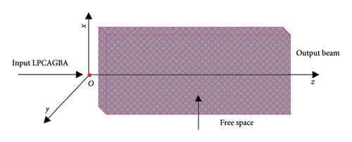
3. Results and Discussion
In this installment, the LPCAGBA propagation characteristics in isotropic free space both within and beyond paraxial approximation will be further investigated. Throughout our numerical study, the following parameters are set as constants unless otherwise specified: a0 = 0.1, ω0 = 1 mm, β = 0.05, and λ = 1.55 μm.
3.1. Paraxial Approximation
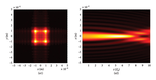
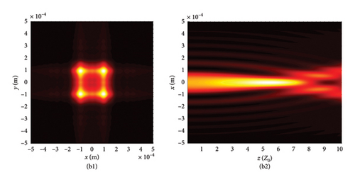
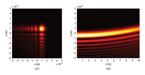
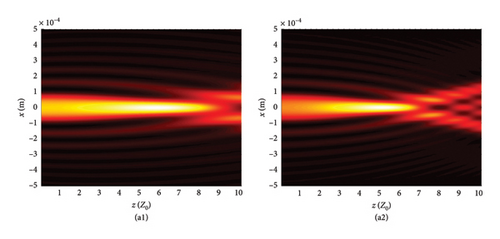
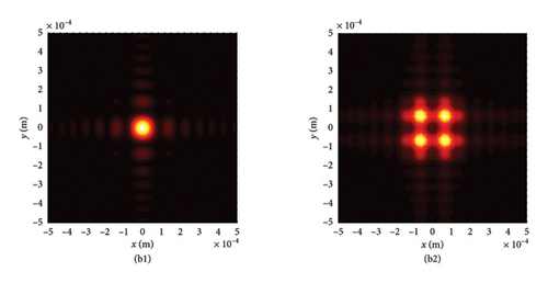
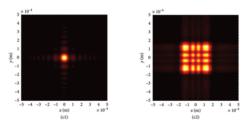
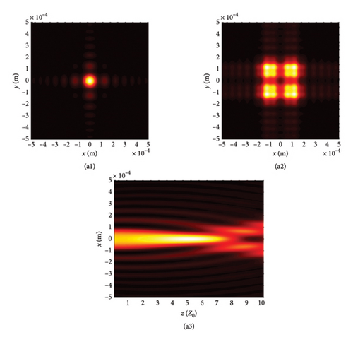
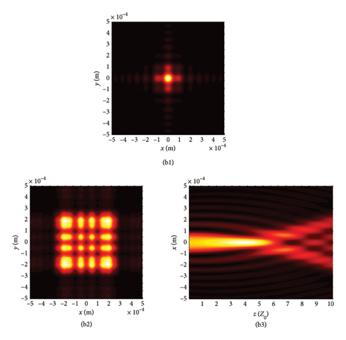
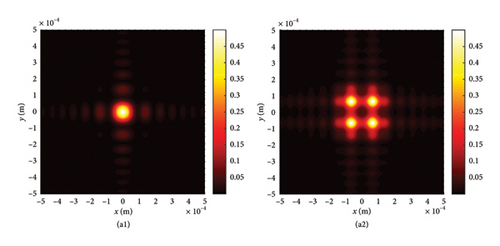
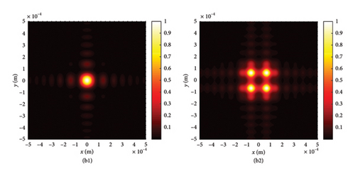
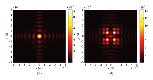
This section begins by examining the effects of different chirp C values on LPCAGBA evolution properties in isotropic free space (n = 1.5). Equation (2) shows that the linearly polarized airy beam array (LPABA) and linearly polarized airy Gaussian beam array (LPAGBA) are two special cases in our model, with the chirp values satisfying C = 0 and C = −i, respectively. The intensity contour graphs at cross section z = 10Z0 and the side view are presented in Figure 2, where Z0 = π /λ is referred to as the Rayleigh length. To compare and analyze the effect of the array on laser evolution quality, we also include the corresponding transmission diagram of single airy beam and airy Gaussian one in Figure 3. Because the x and y variables in equation (7) and (8) can be separated from each other, we will take the side views of (z, x) as examples in the following analysis. Unlike the self-bending of polarized airy beams in Figure 3(a2), where the maximum intensity monotonically decreases with the distance, the self-focusing effect causes LPABA to gather together to the brightest spot at the start of transmission, which is termed as the focal point, as shown in Figure 2(a2). Subsequently, four airy beamlets divide from each other due to the self-bending trait of the beam array. Ultimately, four main lobes in a square, along with several side peaks, are formed in the far field, as demonstrated in Figure 2(a1). It is noted that other polygons can also be formed as the array number is adjusted. Influenced by the Gaussian sources, the maximum intensity of LPAGBA in Figure 2(b2) is consistently weaker than that of LPABA under the same isotropic free space conditions. Additionally, the interference between the main lobes and side lobes in Figure 2(b1) is more pronounced than that in Figure 2(a1), indicating that the chirp C plays a significant role in the beam array’s evolutionary process.
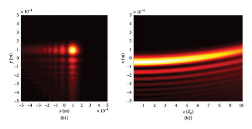
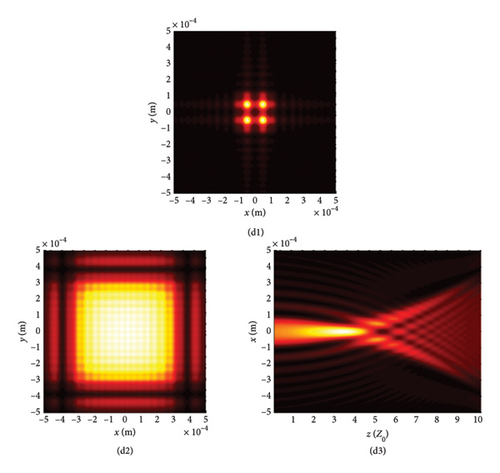
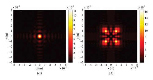
To further elucidate the influence of chirp C on LPCAGBA transformation rules in isotropic free space, we conduct simulations of the beam array’s intensity distribution (z = 10Z0) and side view for values of C ranging from −10 to 10. The results are presented in Figure 4. Here, we focus on a specific scenario: N = 4 and φ = 0, which corresponds to a four-LPCAGBA configuration that is polarization along the x-axis. By comparing Figure 4(a1) with Figure 4(a2), we can clearly understand that the larger the chirp C is uploaded on the input beam array, the more severe the LPCAGBA self-bending degree is acquired when propagating in isotropic free space, which leads to the nearer refocus plane when C is bigger, as portrayed in Figure 4(c1). In stark contrast, the main lobes in Figure 4(b1) are significantly larger than those in Figure 4(c1), indicating that the LPCAGBA with C = −10 is still in the process of self-focusing as it propagates. The calculation results also confirm that the refocal point of the LPCAGBA with C = −10 occurs at z = 0.03 m, which is greater than 5Z0. Furthermore, as the chirp C increases, it is evident that the interference among the LPCAGBA’s main and side lobes becomes more severe in the far field. This can be observed in Figure 4(b2), where the four main lobes are clearly distinguished. On the other hand, the pattern in Figure 4(c2) indicates that a significant amount of energy flows from the main lobes to the side petals, causing a severe distortion in the intensity profile of the LPCAGBA with C = 10.
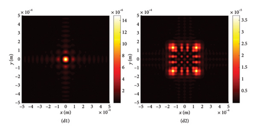
To explore the impact of external surrounding on the evolution rules of LPCAGBA, we analyze the beam array’s intensity distribution and side view in relation to the refractive index (n) of the surrounding medium, as depicted in Figure 5. Upon reviewing these images, it becomes evident that both the chirp and the refractive index can alter the trajectory of the LPCAGBA. Moreover, it is observed that the lower the value of n, the more pronounced the self-bending is stretched in isotropic free space, thereby causing the refocus point to gradually shift forward with the decreasing refractive index n. When examining Figure 5(a1)–(c1), it is evident that the beam array’s main lobes diminish in size as the refocus plane gradually approaches z = 5Z0 from the positive orientation of the coordinate axis, which differs from the scenario depicted in Figure 5(d1) where four main lobes have completely separated from each other, indicating that the beam array progresses from the refocus process to the next self-bending stage. As the LPCAGBA propagates over longer distances (z = 10Z0), the beam array’s main spot size gradually increases as n decreases, as affirmed by the comparison between Figure 5(a2, b2) for C = −10 (or Figure 5(c2) and (d2) for C = 10). This increase is attributed to the augmentation of the self-bending degree by both the chirp C and the refractive index n, resulting in the LPCAGBA profile in Figure 5(d2) being the largest. Additionally, it is evident from these images that the interference and diffraction in the far field cause the energy to gradually converge toward the center of the observation plane as the refractive index n decreases (or the chirp C increases). For example, the four main lobes in Figure 5(a2) can be clearly distinguished from each other due to the hollow dark core, whereas a large square pattern of the beam array is located at the central plane of z = 10Z0 in Figure 5(d2), which differs significantly from the LPCAGBA profile in Figure 5(a2).

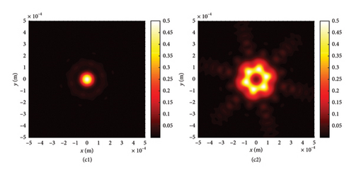
We now shift our focus to the six-LPCAGBA traveling through various isotropic free spaces, ensuring that our conclusions remain universally applicable. The results are presented in Figure 6, where the intersecting surface of the emerging beam array is fixed at z = 10Z0. It is evident that the silhouettes of the main and side petals of the LPCAGBA are determined by the array number N. Meanwhile, the transmission properties of the beam array in free space are primarily characterized by parameters C, n, and z. A comparison between Figures 5(d2) and 6(c2) clearly demonstrates that the analytical formulas and conclusions derived can be applied to the investigation of transmission characteristics for different configurations of airy beam arrays in isotropic free space.
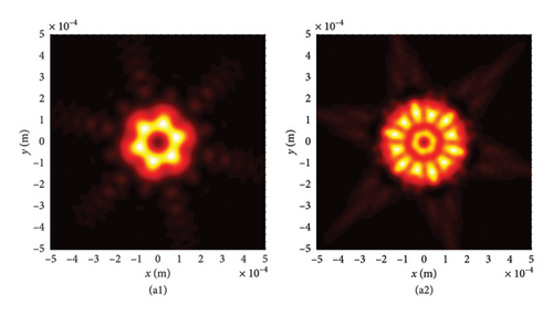
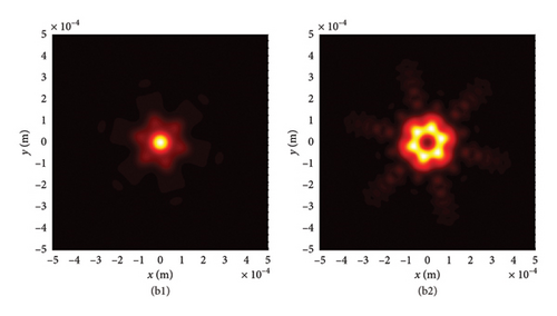
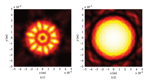
According to equation (19), we find that the ratio between : = cos2 φ : sin2 φ and this proportion remains unchanged on different cross sections. Therefore, it can be seen by comparing four LPAGVBA in Figures 7(a) and 7(b) or six LPAGVBA in Figure 7(c) that the light intensity of each lobe of the LPCAGBA gradually decreases, but its proportion to the paraxial total energy of the LPCAGBA remains unchanged on the corresponding cross section with the increases of transmission distance. This observation confirms that the polarization state of the electric field of the LPCAGBA remains invariant while propagating through isotropic media.
3.2. Nonparaxial Situation
In the nonparaxial situation, not only the x- and y-components (which is described in detail in the upper section) but also the longitudinal component (z-component) of the LPCAGBA emerges even though the intensity of this direction in the initial plane is zero. This indicates that the polarization state of the LPCAGBA electric field vector varies with changes in position during nonparaxial transmission. By viewing Figure 8(a2)–(e2), it is obvious that both the parameter C and n play crucial roles in the evolution of the LPCAGBA longitudinal component, particularly in the far field. Notably, the effects of intensity distribution observed in the nonparaxial component do not significantly differ from those x- and y-components seen during paraxial transmission when φ = 45°. However, it is discovered that the intensity magnitude of the LPCAGBA in the longitudinal direction is considerably smaller than that of the other two components, as confirmed by the color-bar inset in Figure 8. By calculating the gross relative intensity of the LPCAGBA, denoted as Ig = + + , it is evident that the intensity distribution in the nonparaxial setting closely resembles its paraxial approximation, provided all other conditions remain constant.

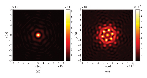
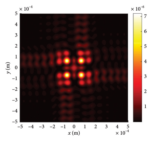
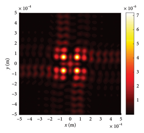
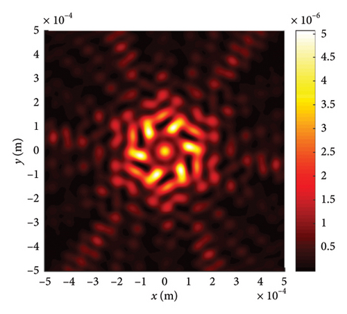
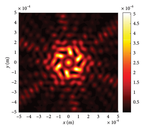
We further demonstrate in this section by examining the influence of φ on the nonparaxial propagation characteristics of the LPCAGBA, as illustrated in Figure 9. It is evident that the deflection of the LPCAGBA longitudinal component varies with changes in φ, which markedly differs from the paraxial x- and y-components. By viewing Figures 8(a2), 9(a), and 9(b), it is obtained that the beam array intensity pattern rotates around the origin counterclockwise as φ increases. In contrast to the four-LPCAGBA profiles of the x- and y-components, which are always symmetrically distributed along the coordinate axes, the symmetry of the longitudinal component only arises when φ = 45°. However, its peak intensity is merely one hundred-thousandth of the total transverse energy at the same transmission distance. These subtle differences suggest that the nonparaxial effects in the longitudinal component cannot be ignored for large incidence angles and in complex optical phenomena, such as high-power laser applications and micro/nano-optics, as well as in systems utilizing free-form optical elements, where the longitudinal component’s intensity becomes significant. Conversely, the paraxial theory provides highly effective analytical results under appropriate conditions.
4. Conclusion and Perspectives
In summary, we have thoroughly explored LPCAGBA evolutionary characteristics in isotropic free space within and beyond paraxial approximation based on the obtained analytical beam array electric expression, and the LPABA and the LPAGBA deemed as two special cases in our model are discussed as well. By analyzing the beam array side view and its intensity contour graph at a certain intersecting surface, it reveals that chirp C plays an important role on beam array’s evolutionary process, and the bigger the C is, the more severe the LPCAGBA self-bending degree is achieved when propagating in isotropic free space. In contrast, the LPCAGBA self-bending is enhanced when decreasing the refractive index n of the environments. For the general LPCAGBA, composed of x- and y-components, we find that the intensity profiles along these axes remain unaffected by φ, but its energy value in both x- and y-directions varies with changes in φ. Our findings suggest that by adjusting the parameters C, n, and φ, the profile and the refocus point of the LPCAGBA can be controlled within the paraxial approximation. Furthermore, in the nonparaxial scenario, the longitudinal component of the LPCAGBA emerges even though the intensity of this direction in the initial plane is zero, but the magnitude is far less than that of the x- and y-components. Unlike the paraxial components, the longitudinal component of the beam array intensity pattern rotates around the origin counterclockwise as φ increases.
The insights gained from this research will contribute to a better understanding of the propagation behavior of the LPCAGBA both within and beyond the paraxial approximation. These findings hold particular relevance in precision optical analysis, such as in the design and operation of optical tweezers and ultrafast and nano optics. Furthermore, our study lays the foundation for the development of more sophisticated models in laser optics, including various types of beam arrays propagating in anisotropic mediums. These advancements represent the next steps in scientific research within this field.
Conflicts of Interest
The authors declare no conflicts of interest.
Funding
The authors gratefully acknowledge the research grants provided by the Natural Science Foundation of Hubei Province (no. 2024AFD109).
Acknowledgments
The authors gratefully acknowledge the research grants provided by the Natural Science Foundation of Hubei Province (no. 2024AFD109).
Open Research
Data Availability Statement
The data used to support the findings of this study are available from the corresponding author upon request.


