Single-Layer Metasurface-Based Wideband Circularly Polarized Antenna Using CMA With RCS Reduction
Abstract
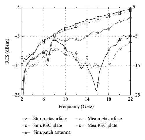
A low-profile wideband circularly polarized (CP), single-layer antenna with low radar cross section (RCS) reduction based on staggered elliptical metasurface using characteristic mode analysis (CMA) is presented. The staggered arrangement of the elliptical metasurface has a 90° relationship, ensuring the generation of circular polarization, and their modes of fusion can achieve RCS reduction by CMA. The defective ground shows that the difference in characteristic angle (CA) between the two pairs of modes is about 90°. The measured results show that the antenna has a 40.6% (5.5 GHz–8.3 GHz) impedance bandwidth (IBW), a 26.2% (6.3 GHz–8.2 GHz) 3-dB axial ratio bandwidth (ARBW), and a peak gain of 5.1 dBic is achieved at 6.3 GHz, and with a large RCS reduces across the frequency range from 2.0 GHz to 22.0 GHz (166.7%). Monostatic RCS reduction of more than 5 dBsm is achieved within the frequency range from 4.6 GHz to 22.0 GHz (130.8%).
1. Introduction
Microstrip antennas are widely used in various complex communication devices due to their easy implementation of broadband and CP, low cost, easy integration, and low profile [1]. With the deepening of scientific research, it has been found that periodic or nonperiodic arrangement of the same or similar subwavelength metal units can produce special electromagnetic characteristics, such as negative refractive index, negative magnetic permeability, and negative dielectric constant [2]. They can form special electromagnetic control functions such as frequency selective surfaces [3], high impedance surfaces [4], and holographic imaging [5]. Loading metasurface into antennas can effectively improve antenna performance, such as bandwidth, polarization, and gain. Therefore, studies on the design of metasurface antennas based on metamaterial structures have received increasing attention.
The design of metasurface CP antennas can be roughly divided into two types: one is to use metasurface to excite CP waves, which have a 90° relationship [6, 7], and the other is symmetric metasurface, whose CP waves are excited by other forms, such as microstrip or gap [8, 9]. In fact, there is a CMA method that intuitively analyzes broadband and polarization characteristics in the selection and design of metasurface. In [10], a metasurface composed of square patches of different sizes achieves broadband performance, and this arrangement widens the bandwidth of the mode by the mode significance (MS) of the CMA. A 4 × 4 rectangular metasurface was analyzed, with a CA difference of approximately 90° and the orthogonal characteristic current (CC), to achieve a single-layer CP metasurface antenna with a 25% IBW, a 19.42% 3 dB ARBW [11]. For symmetric metasurface, the characteristic mode mainly analyzes the CC, and the necessary condition for achieving CP is that the CC is orthogonal. In [12, 13], double-layer metasurface CP antennas are designed, with the metasurface consisting of square patches and the CC of its two modes being orthogonal, achieving 3 dB ARBW of 3.0% and 11.6%, respectively. The metasurface is not only capable of designing broadband and CP antennas, but they are also an ideal choice in the direction of antenna stealth. Low RCS antennas using single-layer substrate coaxial feeding [14, 15] and double-layer substrate microstrip feeding [16, 17] have been reported. Besides, a phase-gradient metasurface is designed to achieve 96.3% low RCS bandwidth [18]. An antenna connected to a circular groove metasurface feeder achieves 8% ARBW and 85.7% low RCS bandwidth [19], and the slotted and chamfered polarization metasurface of another antenna has an ARBW of 15.9% and a low RCS bandwidth of 104.3% [20]. In [21, 22], methods for RCS reduction have been discussed, which also offer supplementary benefits for designing high-performance antennas and further reducing RCS.
In this paper, a wideband CP single-layer metasurface antenna analysis with low RCS is proposed, which uses an elliptical metasurface staggered arrangement and combined with CMA to achieve broadband, CP, and low RCS performance. In addition, combined with the microstrip monopole antenna structure, the CP bandwidth is maintained to be wider, and the CA of its two modes is close to 90°, ensuring the generation of CP waves. The operational bandwidth of the proposed antenna can be applied to the C-band of satellite communication systems.
2. Design and Analysis of the Proposed Antenna
2.1. Antenna Configuration
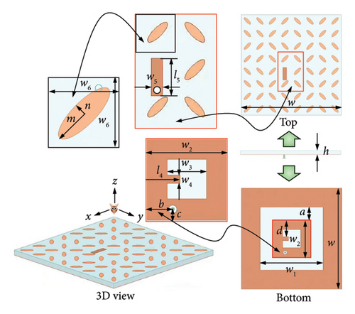
The proposed antenna consists of an elliptical patch metasurface, a microstrip patch, a single-layer substrate, and a ground, with a simple structure and low cost. The elliptical patch is arranged in a special staggered pattern. The ground has formed defects through cutting slots. The microstrip patch and defective ground form a microstrip monopole antenna, ensuring the scalability of impedance bandwidth. The exploded view structure and dimensions of the proposed antenna are shown in Figure 1. This metasurface antenna was simulated by HFSS software and CST software with the F4B substrate (the dielectric constant εr = 2.65 and the tangent loss tanδ = 0.0015).
2.2. Characteristic Mode Analysis
The characteristic mode theory (CMT) [23, 24] has been recognized and confirmed in scientific research and engineering design. Solving the generalized eigenvalue equation can directly obtain two physical quantities related to the characteristic mode, namely, the CC Jn and the eigenvalue λn. However, substituting these two physical quantities into different formulas can construct more physical quantities, which can better help antenna designers understand the physical mechanisms of antenna radiation or scattering. These physical quantities related to characteristic modes are collectively referred to as characteristic mode–related quantities. A clear understanding of characteristic mode–related quantities is the basis for fully utilizing the advantages of CMA. The commonly used feature pattern correlations include eigenvalues, MS, CC, CA, and characteristic electric fields. The indicators of resonance in the CMT mainly depend on whether MS has reached the potential for resonance (MS ≥ 0.707). When MS is equal to 1, this frequency point is the mode resonance point. When MS is greater than or equal to 0.707, this frequency band is the mode resonance bandwidth.
Figure 2(a) shows three types of arranged and combined cells, which are composed of four elliptical patches arranged in an orthogonal relationship. Figures 2(a), 2(b), 2(c), and 2(d) show the MSs of three types of cells, which are almost identical. Mode 1, Mode 2, Mode 4, and Mode 5 experienced resonance in the frequency band. Mode 1 and Mode 2 overlap, with the main mode having a wider resonant bandwidth, while other modes serve as auxiliary modes. Its resonance point occurs at similar frequency points but slightly different. Figure 3 shows the CC at their resonance points, and their current directions can be seen as orthogonal. The proposed metasurface is designed with an orthogonal orientation, which facilitates the generation of CP waves and contributes to reduced RCS. The fusion of currents from Mode 1, Mode 2, Mode 4, and Mode 5, as illustrated in Figure 3, results in the current distribution as shown in Figure 4 under plane wave incidence. This specific current distribution is the primary factor in achieving low RCS. Figure 4 illustrates the mode fusion current at 10.5 GHz, highlighting its crucial role in RCS reduction. Figure 5 shows the RCS reduction results for three types of cells, with RCS below −23 dBsm in this observation interval, which means that these three types of metasurface units have low RCS values and the potential for a RCS reduction after combination.
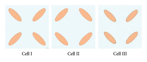
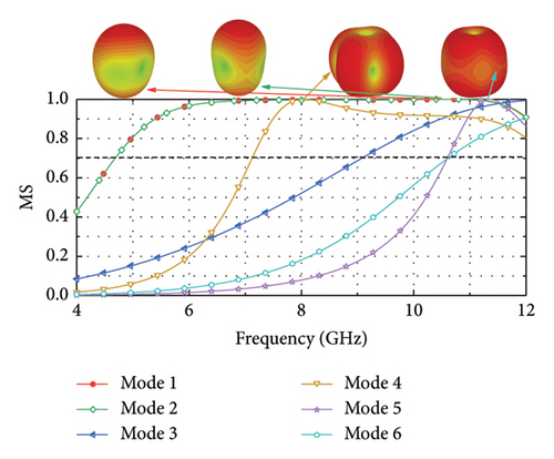
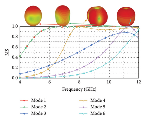
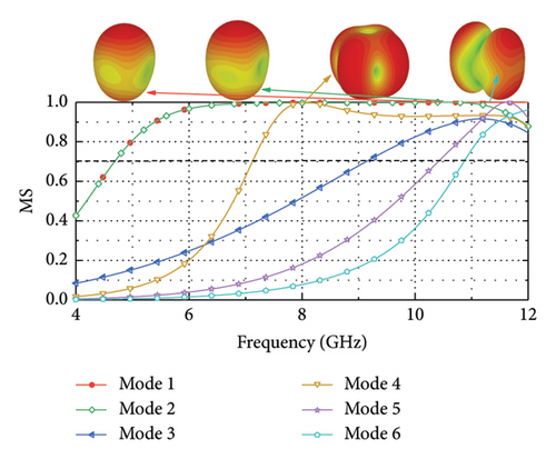


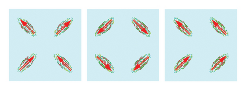
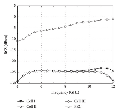
Figure 6(a) shows the structure of the defective ground, and the results of its characteristic mode analysis are shown in Figures 6(b), 6(c), and 6(d). The defective ground structure is orthogonal, so the CC is also orthogonal.

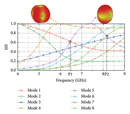
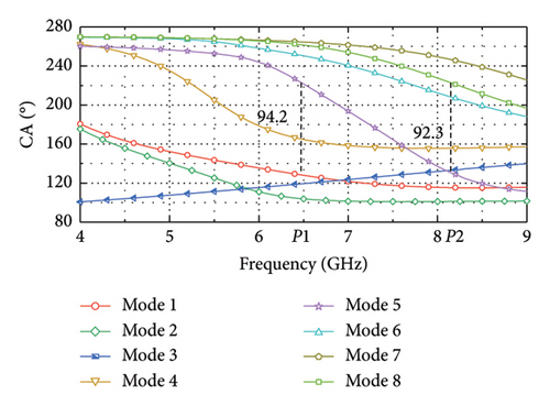
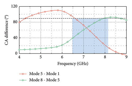
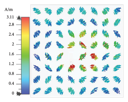
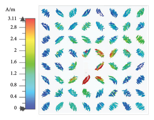
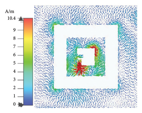
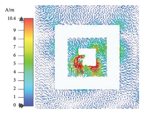
There are two modes of resonance in the MS of the defective ground in the frequency band. Mode 4 resonates at 5.96 GHz with a resonance bandwidth of 5.19 GHz–9 GHz, and Mode 5 resonates at 7.37 GHz with a resonance bandwidth of 6.58 GHz–8.25 GHz. There are two pairs of modes with a CA difference of 90° in their MS interaction, namely, Mode 1 and Mode 5 at 6.47 GHz (94.2° at P1) and Mode 5 and Mode 8 at 8.17 GHz (92.3° at P2). According to the CMA, resonance can occur within the frequency band, and CP waves can be excited. Its impedance bandwidth is excited by the main mode, while CP is excited by both the main mode and higher-order modes. Figure 7 shows the surface current of the proposed antenna after excitation. The central patch of the metasurface functions as a radiation patch, akin to a transmission line, and is fed by a coaxial connection. This radiation patch is strategically positioned to form an orthogonal relationship with the branches on the defected ground plane, which is crucial for exciting CP waves. Both its position and size significantly influence the bandwidth of the CP waves and are essential for ensuring their effective generation.
3. Antenna Prototype and Measurement
To verify the application of the designed elliptical metasurface in CP antennas, the proposed wideband CP single-layer metasurface microstrip antenna was fabricated and measured, as shown in Figure 8. The prototype is measured with a |S11| < −10 dB bandwidth of 40.6% (5.5 GHz−8.3 GHz), a 3 dB ARBW of 26.2% (6.3 GHz−8.2 GHz), and a peak gain of 5.1 dBic at 6.3 GHz, as illustrated in Figure 9.
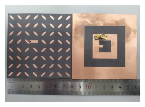
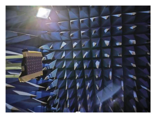
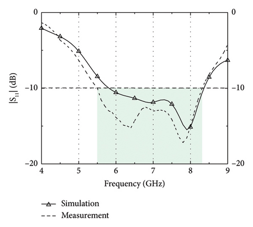

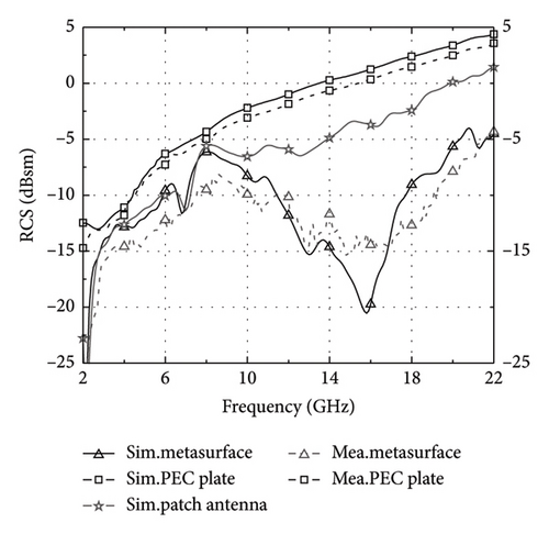
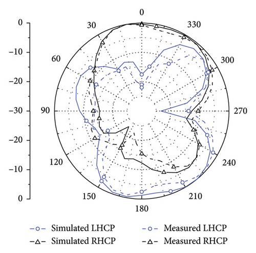
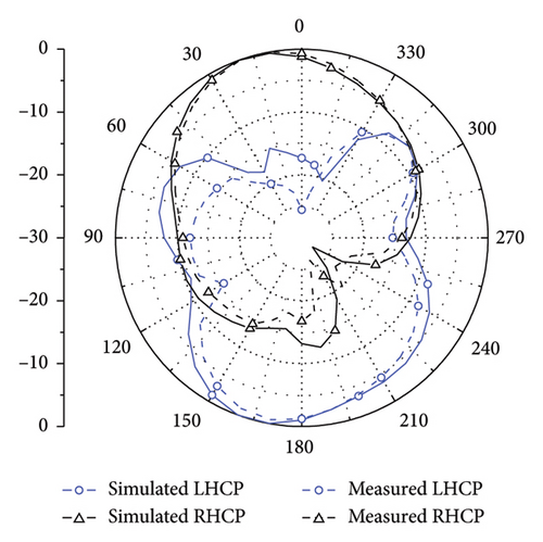
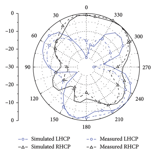
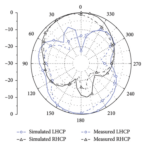
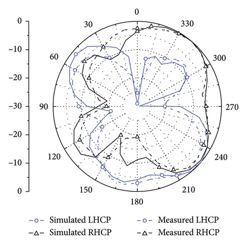
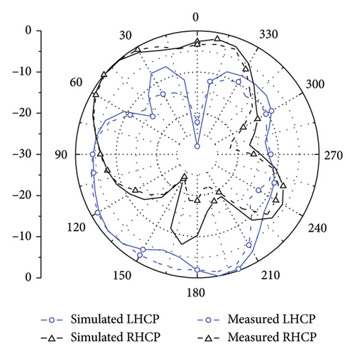
Figure 10 compares the monostatic RCS of the proposed antenna with that of a copper plate and a patch antenna under normal incidence. The proposed antenna exhibits a RCS reduction bandwidth of 166.7% (2.0 GHz–22 GHz) compared to a copper plate of the same dimensions. Additionally, it achieves an RCS reduction greater than 5 dBsm within the frequency range of 4.6 GHz–22 GHz, representing a 130.8% improvement. This demonstrates a significant RCS reduction across the specified frequency band. Figure 11 shows that the RHCP and the LHCP. Table 1 shows a comparison of several related antennas published in the literature, indicating that the proposed antenna performs relatively well in most aspects. The measurement results of the proposed antenna are in good agreement with the simulation results, with slight errors.
| Ref. | Layer | Profile (λ0) | IBW (%) | AR BW (%) | Peak gain (dBic) | RCS BW (%) (dB) | Type |
|---|---|---|---|---|---|---|---|
| 2023 [7] | 1 | 0.05 | 18.6 | 18.6 | 5.0 | N. A | Metasurface slots |
| 2016 [8] | 1 | 0.07 | 33.7 | 16.5 | 5.8 | N. A | Metasurface |
| 2023 [11] | 1 | 0.06 | 25.0 | 19.4 | 8.0 | N. A | CMA metasurface |
| 2020 [12] | 2 | 0.08 | 4.0 | 3.0 | 4.1 | N. A | CMA metasurface |
| 2023 [13] | 2 | 0.05 | 14.5 | 11.6 | 4.3 | N. A | CMA metasurface |
| 2018 [15] | 1 | 0.02 | N. A | N. A | 4.0 | 80.0 | Metasurface slots |
| 2018 [18] | 3 | 0.02 | 4.7 | N. A | N. A | 96.3 | Metasurface slots |
| 2018 [19] | 2 | 0.10 | 18.2 | 8.0 | N. A | 85.7 | Metasurface slots |
| 2021 [20] | 1 | 0.06 | 19.0 | 15.9 | 5.66 | 104.3 | Metasurface slots |
| 2018 [21] | 1 | 0.02 | 0.3 | N. A | N. A | 60.3 | Metasurface slots |
| 2018 [22] | 2 | 0.66 | 18.6 | N. A | 4.9 | 76.9 | Metasurface slots |
| This work | 1 | 0.07 | 40.6 | 26.2 | 5.1 | 166.7 | CMA metasurface |
4. Conclusion
A wideband CP single-layer metasurface antenna has been designed and validated by measurement. By conducting mode analysis on metasurface and defect ground, CP performance and low RCS were achieved. From metasurface design to antenna optimization and fabrication, the feasibility of the proposed antenna design and analysis has been verified. This proposed antenna exhibits several advantageous characteristics including low profile, CP, broadband capability, cost-effectiveness, simple structure, and low RCS. Its operational frequency band makes it suitable for C-band wireless communication systems.
Conflicts of Interest
The authors declare no conflicts of interest.
Funding
This work was supported in part by the Postgraduate Research & Practice Innovation Program of Jiangsu Province in China (KYCX23_0467), Postdoctoral Research Foundation of China (2023M731680), and Youth Foundation of Jiangsu Province (BK20230919).
Open Research
Data Availability Statement
All data generated or analyzed during this study are included in this article.


