A Novel Anti-DRFM Active Jammer Method for Two-Station Netted Radar Based on Extended Kalman Filtering
Abstract
Active jammers in the form of digital radio frequency memory (DRFM) could produce false targets with a coherence of range and velocity, making it increasingly efficient in interrupting radar systems based on data correlation analysis. By integrating the temporal variability characteristic and mitigating the impact of measurement errors inherent in the radar system, we propose a novel false target recognition methodology for a two-station netted radar utilizing extended Kalman filter (EKF) and the Neyman–Pearson criterion. From the aspects of filtering characteristics and active jammer parameters, the simulation shows that the technique could obtain observable different convergence curves for false targets and is sensitive to velocity or range deception under specific parameters. Moreover, the method exhibits a favorable tolerance for measurement error and an exceptional capability to identify false targets from various directions, considering both radar performance parameters and spatial scale. This outcome highlights the significance of setting specific parameters following countermeasure scenarios and requirements, showcasing its practical value in engineering practice.
1. Introduction
The rapid development of DRFM resulted in increasing fidelity of the radar spoofing signals formed by forwarding [1, 2]. By entering the radar receiver, such signals mimic the characteristics of the original signal and form spoofing false targets. From the perspective of information entropy [3], DRFM results in the loss of radar’s effective information. To address this issue, an important way to tackle DRFM interference is to compensate for the corresponding loss of effective information. One of the effective methods is to use multistation radars [4, 5] to increase effective detection data.
There are several techniques to tackle active jammer spoofing interference caused by DRFM. In terms of interference mechanisms, since the active jammer forwards the radar signal, the spoofed false target is spatially located on the line between the radar and the jammer [6]. In cases where the jammer is used to spoof multiple radars simultaneously at different locations, this constraint makes it difficult to obtain position and velocity coherence for the false target [7, 8], meaning there is only one false target in space. Each radar will find one target, but the measured results of the one target are not the same. This drawback in active jammers is exploited by authors in [9, 10], where they proposed the point-trace association method to recognize false targets. Many of the subsequent works are built upon this idea.
Nevertheless, the method in [9, 10] has a high probability of misclassification for long-range false targets. To address this issue, the authors in [11, 12] consider the target velocity characteristics based on point-trace association and propose a multiprocess recognition method, which reduces the misjudgment probability of long-distance targets to a certain extent. Furthermore, in [13–15], the localization bias is introduced for multistation radars to improve the robustness of the recognition method. The goniometric information is also proposed by authors in [16, 17], based on which they propose the nearest neighbor-angle information multiprocess recognition method. As seen above, most multistation radar systems recognize active false targets using data fusion, which helps distinguish real targets from false ones using the fused radar–measured data [18, 19].
Most data fusion methods used in radar electronic countermeasures (ECMs) are based on the correlation analysis between the position, velocity, and trajectory that can ideally deal with most spoofing interference. In practice, however, due to the limited measurement accuracy, especially for the long-range targets [20], the position and velocity coherence requirements for the targets are often given within an interval. DRFM forwarding delay is also at the microsecond level, resulting in a better spatial “homology” of the false target [21, 22]. The recognizing methods proposed in the literature referred above mainly have the characteristic of static discrimination, which ignores the feature that the generated false target will change with the position of the jamming platform. Therefore, considering the “homology,” the false targets will likely pass the multiradar data fusion test.
In this paper, to reduce the impact of measurement errors of the radar system and enhance the capability to recognize the false target generated by DRFM, we have incorporated the characteristics of temporal variation characteristics of the false target and proposed a true-false target discriminant model for two-station netted radar system, which based on the method that combines extended Kalman filter (EKF) and Neyman–Pearson criterion. This proposed approach allows for the accumulation and amplification of spatiotemporal noncoherence associated with DRFM false targets, enabling the calculation of the probability that a false target is misjudged as true. Simulations show that the convergence curves obtained by EKF are different for the false target. From the aspect of active jammer and radar parameters, it indicates that the method could recognize the false target if the spoofing distance is larger than 50 m or the spoofing speed exceeds 18 m/s, and the radar measurement error of speed and distance will affect the discriminating effect. Furthermore, considering the space scale, the proposed method could discriminate the false target from most directions.
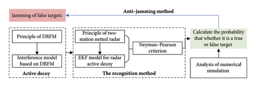
The organization of this paper is as follows, also as shown in Figure 1. In Section 2, the operation principle of DRFM is analyzed and a data-level DRFM interference model is presented. Section 3 analyzes the principle of two-station netted radar against active jammer and establishes the system state equation and the observation equation under redundant observation data to build an EKF model. Section 4 discusses the Neyman–Pearson criterion–based recognition method and analyzes the true target probability. Then, in Section 5, numerical simulation analysis is conducted to compare the filtering characteristics of the real and false targets from several previous works and analyze the applicability of the method on different spatial scales. Section 6 provides a summary of our work.
2. Interference Principle of DRFM-Based Jammer
2.1. DRFM Jammer
The DRFM-based active jammer detects and receives threatening radar signals from the environment and then extracts the signal parameters. A jamming controller is then used to forward a specifically modulated false echo signal. The false echo signal enters the radar receiver through the antenna’s main lobe or side lobe, implying a potential target in a certain area of radar reconnaissance. In the radar, the false echo signal may also be used to obtain the false target parameters such as velocity or distance. The schematic diagram of DRFM is illustrated in Figure 2.

In the DRFM system, if the radar signal was intercepted by the jammer, its in-phase and quadrature components would be downconverted to IF signal, respectively. Subsequently, after sampling, quantizing, and coding, the jammer controller could manipulate the resulting data before being upconverted and retransmitted back to the victim radar. Considering the signal process, there is a delay between the false target generated by DRFM and the position of the jammer itself.
For the airborne jammer, the interference effect caused by DRFM is to form false targets located virtually between the true target and the jammer. These false targets can cover the real target and confuse the radar, making it unable to form a stable track, hence interrupting the radar tracking system [23, 24]. In addition to conventional airborne jammers, unmanned airborne equipment can also be used to carry jammers for electronic interference operations [25–27]. Unmanned airborne equipment often has a small RCS, hence not easily detected by radars, and therefore capable of conducting jamming operations closer to the radar. Using DRFM, one may create multiple false targets to be detected by the enemy’s radar systems while there is no real target in reality. Such an operation confuses the radars and consumes detection resources [28]. From the processing flow of the DRFM jammer, it can be seen that there is a delay between the generated false target and the position of the jammer itself, which would introduce inevitable deception situation bias for radar and is the starting point of the research in this paper.
2.2. Interference Model of Two-Station Netted Radar
Based on the jamming mechanism, it is easy to show that the forwarding process creates a false scattering point or false target located on the line between the jammer and radar [6]. In cases where the jammer receives multiple radar signals simultaneously, it can also interfere with multiple radars simultaneously [19].
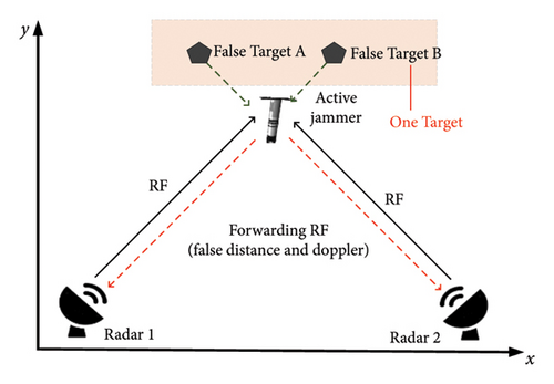
Figure 3 presents an instance of such a scenario where a single active jammer interferes with a two-station netted radar. As seen in Figure 3, Radar 1 and Radar 2 simultaneously cover the region in the space. The active jammer receives two radar signals within its reconnaissance angle and simultaneously forwards them to create false targets A and B on the spatial link between the jammer and Radar 1 and 2, respectively. If Radar 1 and Radar 2 are sensitive and error-free, the false target can be effectively filtered out after applying the intersection processing to the measurement results. However, in practice, for distant targets, the measurement error of the radar results in creating false targets A and B located in the same resolution cell of Radar 1 and Radar 2 (see the shaded area in Figure 3). To filter the false target, we can calculate the intersection of targets detected by Radar 1 and Radar 2. However, when false targets A and B are located in the same resolution cell, it cannot help.
In equation (2), f denotes RF signal frequency, Δf is Doppler shift caused by jammer motion, and f1 denotes the spoofing modulation frequency. Furthermore, in (2) fr1 and fr2 are the measurement results of a multistation radar system. For a stationary jammer, Δfr1 = Δfr2 = 0, and the system of equations in (2) has only one unknown variable; therefore, fr1 = fr2, which is the principle presented in equation (1). However, when the jammer is in motion, the system in (2) includes three unknown quantities and only two equations, from which the Doppler characteristics cannot be obtained, and therefore it cannot be determined whether the target is true or false.
3. EKF Process of Netted Radar
As shown in Section 2.2, it is difficult for the two-station netted radar to recognize whether a target is true or false. Considering that the measurement results of the two-station netted radar contain the absolute values of the position and velocity of the target in the natural coordinate system [11], the EKF can be used to analyze the intrinsic correlation among the target motion, the measurements, and the measuring errors through time accumulation based on a series of continuous measurement results and recognize the false target.
3.1. The Principle of Two-Station Netted Radar
The proposed method of the two-station netted radar with EKF is aimed at the shortcomings of the DRFM forwarding mechanism. Although DRFM can generate a forwarded signal with high fidelity, this signal is delayed. This deviation results in the measured Doppler frequency shift (caused by jammer movement) being different from the motion characteristics of the false target. The approach here is to use time accumulation and filtering processing to amplify the tracking error caused by forwarding delay and identify the active jammer. At the same time, the measuring error can also be reduced.
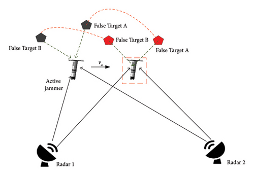
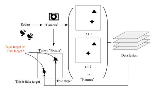
The process is shown in Figure 4. Assume that the active jammer moves at velocity va, and the false targets A and B are virtually moved due to the movement of the active jammer (see Figure 4). The trajectory of the false target A (B) measured by Radar 1 (Radar 2) is, therefore, an arc centered on Radar 1 (Radar 2). The difference between the two tracking trajectories accumulates the erroneous component of the measured false targets, which can then be used to identify the existence of the active jammer. Suppose that a single measurement could be understood as a camera exposure, as shown in Figure 5. As seen in a single “photo,” it is confusing to distinguish between true and false targets; however, by accumulating multiple consecutive “photos” over time and fusing these photos, one can clearly distinguish them. The two-station netted radar provides primary measurement data for this fusion process based on the EKF, presented in the following subsection.
3.2. EKF Equations for Two-Station Netted Radar
The netted radar’s measurements are uncertain and discrete time [29, 30]. Considering the two-station netted radar and the measured target as one system, the data can be fused based on EKF [31, 32]. From this, the status equations and observation equations can be constructed as follows.
3.2.1. Status Equation
3.2.2. Observational Equation of a Monostatic Radar
3.2.3. Observational Equation of Two-Station Netted Radar
For state estimation, any of the equations in equation (11) can be used as the Jacobian matrix of the observation equation. Using this approach, based on two radar measurements, two estimation methods can be used. Hence, two EKF curves are obtained that correspond to a single status of the target. By comparing the difference between these two EKF curves, one can recognize whether or not this is a true target.
For the true target, the corresponding errors of the two estimation methods are mainly created by radars’ measurement errors, which follow similar trends. However, when the tracked target is a false target caused by an active jammer, the velocity and position of the false target are less consistent. Note that although the jammer can spoof the two-station netted radar in terms of resolution, due to the jammer’s forwarding delay and Doppler shift, the two estimation methods show significant deviation after filtering.
3.3. Updating Process
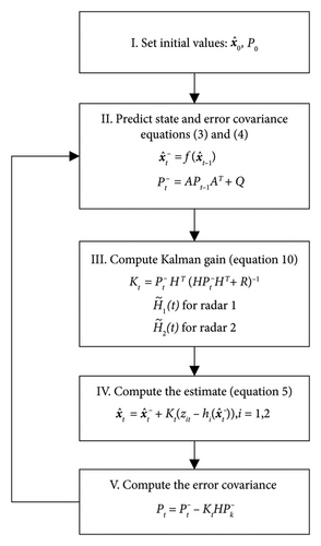
The updating process of the EKF-based method is presented in Figure 6, which contains five steps. In the third and fifth steps, H equals for Radar 1 and equals for Radar 2. The method reconstitutes the observed data into two vectors for separate filtering according to (11). As it is seen, there are two filtering processes. However, considering that the data come from the same sets of observations [r1, α1, v1, r2, α2, v2], only one computing thread is designed to speed up the computation.
4. The False Target Recognized Method
Section 3 proposed an EKF-based method that generates two status curves corresponding to each observed or tracked target. The two curves should have similar convergence trends for the true targets. Intuitively, in cases where there is an active jammer, these two curves are different. We propose a quantitative judgment based on the Neyman–Pearson criterion to measure the difference between the filtering curves.
4.1. Method of Comparing the Curves
The convergence curves L1 and L2 are affected by the process noise and measurement errors. Therefore, if equation (12) is calculated directly, large local randomness can easily accumulate random errors and increase the probability of fault target recognition.
4.2. The Neyman–Pearson–Based Method
In equation (13), f(ak, bk) indicates whether ak − bk is in the confidence interval or not. D denotes the percentage of samples that satisfy the constraint. By setting a threshold M, D and M are then compared to determine whether the target is a true target. If D > M, the detection target is true and the netted radar is not being jammed.
5. Numerical Simulations
The simulated system includes a two-station netted radar and an active jammer. The parameters of the two-station netted radar include two aspects: spatial scale position and measurement accuracy. For the active jammers, the main parameters include the system noise, jammer motion parameters, and jammer interference performance parameters. These parameters are presented in Table 1.
| Parameters | Note |
|---|---|
| xa | Jammer position of x-coordinate |
| ya | Jammer position of y-coordinate |
| τa | Signal forwarding delay |
| Jammer speed of x-coordinate | |
| Jammer speed of y-coordinate | |
| RMS error of processor noise of jammer | |
| xr1, xr2 | Radar 1 and radar position of x-coordinate |
| yr1, yr2 | Radar 1 and radar position of y-coordinate |
| r1, r2 | Distance value from Radar 1 and Radar 2 ranging |
| α1, α2 | Angle value from Radar 1 and Radar 2 direction finding |
| v1, v2 | Velocity value from Radar 1 and Radar 2 speed finding |
| dr1, dr2 | RMS error of Radar 1 and Radar 2 ranging |
| dα1, dα2 | RMS error of Radar 1 and Radar 2 direction finding |
| dv1, dv2 | RMS error of Radar 1 and Radar 2 speed finding |
| te | Filtering time |
5.1. Filtering Characteristics of True and False Targets
Assuming a simple detection scenario where the parameters are set as follows. The true target is set at xa = 9000 and ya = 9000, with a speed of , , and , and the filtering time te = 5 s. The active jammer has the same starting position as the true target, and its signal forwarding delay is τa = 2us. Combined with the light speed, the corresponding distance error caused by forwarding delay is 600 m.
Here, the position of Radar 1 is xr1 = 0, yr1 = 0, and the position of Radar 2 is xr2 = 3000, yr2 = 0. The RMS errors of Radar 1 and Radar 2 are dr1 = dr2 = 10 m, dα1 = dα2 = 3°, and dv1 = dv2 = 1m/s. The filtering curves of the true and false targets are shown in Figure 7.
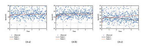


Figure 7 shows that for the real target, the measurement results of Radar 1 and Radar 2 have a good agreement, with only minor fluctuations caused by the measurement errors. For the distance deception caused by forwarding delay, the velocity and position measurement results show observable variability. In terms of convergence trend, the measurements converge in the same way, which can reflect the movement of the active jammer. For the velocity spoofing false target, the velocity and position measurements diverge as time advances, and the trends are significantly different. Through Figure 7, it is easy to see (a) is the true target and (b) and (c) are the false targets. Figure 7 also suggests that one can recognize true or false targets from different indicators.
5.2. Impact of the Active Jammer Parameters
The value D defined in Section 4.2 refers to the probability that the method judges a false target as true. This is plotted in Figure 8 for different distance spoofing and different speed spoofing.
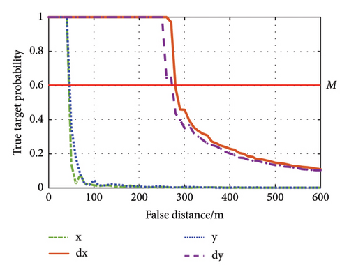
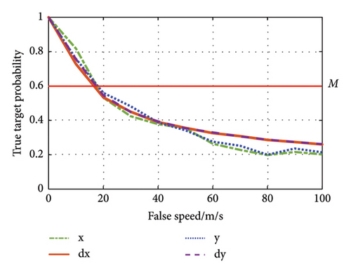
As seen in Figure 8(a), the radar ranging function is more sensitive to distance spoofing than that of the radar speed measurement. For M = 0.6, if the spoofing distance is larger than 50 m, the target can be detected as a false target by the two-station netted radar. Note that in cases where the system is jammed by spoofing velocity, the sensitivity of the two-station netted radar to discriminate between true and false targets by each indicator is approximately the same. For M = 0.6, if the false velocity is more than 18 m/s, the false target will be detected.
For the cases where the system is jammed by range-velocity joint deception, the value D is changed under four indicators, see Figure 9.
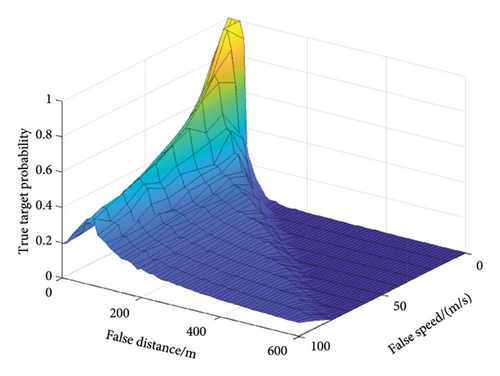
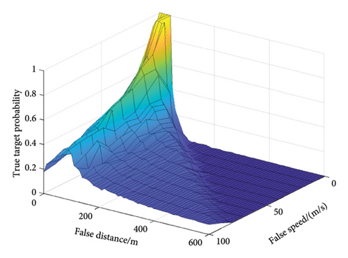
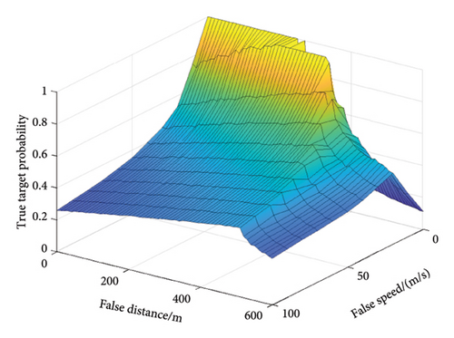
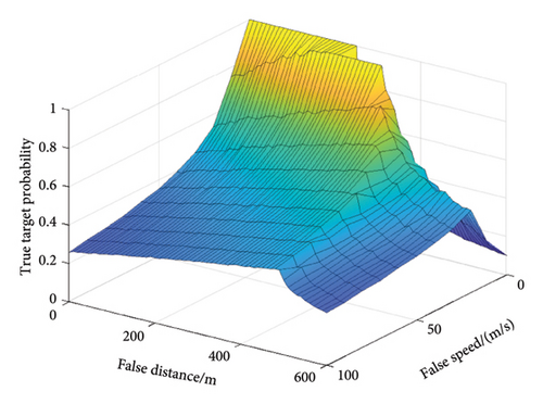
From the localization perspective, the contribution of range deception to false target recognition is higher than that of the velocity deception. Also, from the perspective of speed finding, the contribution of error introduced by velocity deception to the false target recognition is higher than that of the distance deception. Furthermore, fixed range-velocity joint deception produces a lower misjudgment probability as it introduces more erroneous information. One can make false targets more confusing by matching the speed and distance in time and space.
5.3. Impact of the Two-Station Netted Radar Parameters
For the netted radar, it can be intuitively seen that the larger the radar measurement error is, the more difficult it is to recognize the false target. How the measurement error affects the misjudging probability is shown in Figure 10.
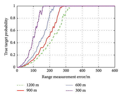

In Figure 10(a), the horizontal axis indicates the range measurement error of each radar, and the different curves indicate the probability of discriminating the false target as the real target at different deception distances. It can be seen from the figure that as the distance measurement error increases, the probability of misjudging gradually increases. When the error reaches a certain value, it cannot discriminate the real and false targets from the distance characteristics. It can be found that the error value has to be smaller than the deception distance to distinguish the true from the false target, but it is not proportional to the deception distance. The range measurement error should be less than 200 m for better performance. In Figure 10(b), there is an increased probability of misidentification under a smaller velocimetric error for velocity spoofing since the range error forms a chance agreement with the velocimetric error. It can still distinguish between true and false targets when the velocimetric error exceeds the velocity value.
5.4. Discrimination Ability for Different Space Scales
The analysis above suggests that the proposed method in this paper is not only affected by the performance parameters of the jammers but also related to the relative spatial location of the group radar and the jammers. In this section, we assume that the jammers are located at different positions in space and the two radars are located at different positions. Then, we obtain the misjudgment probability through simulation. The results are shown in Figure 11.
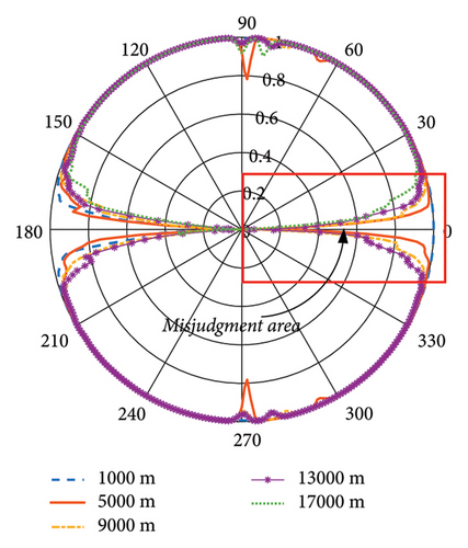
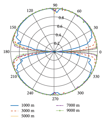
In Section 5.1, we set Radar 1 xr1 = 0, yr1 = 0 and Radar 2 xr2 = 3000, yr2 = 0. The position of the jammer is (9000, 9000). Here, we put the active jammer around Radar 1, and its position is written in terms of polar coordinates. In Figure 11(a), we change the distance from the active jammer to Radar 1 and see whether it can discriminate the false target from a different direction. The curves represent the judgment probability, and it can be seen that the false target can be recognized from most directions, but there is still a misjudgment area, and it increases with distance. In Figure 11(b), we put Radar 2 at a different position and see how the distance between Radar 1 and Radar 2 influences the judgment probability. It can be seen that the greater the distance, the smaller the misjudgment area is. In practice, long distance between netted radars means high demand for communication, which is not the focus of this paper.
6. Conclusion
Active jammer deception interference is a critical way to occupy radar detection resources. In this paper, we analyze the operational mechanism of DRFM and consider the synchronization of speed and position for an active jammer false target in a two-station netted radar system. Consequently, we propose a recognition model for distinguishing true and false targets based on combining the EKF and Neyman–Pearson criterion. The approach makes full use of the redundant detection data in the target detection process and enables the calculation of the probability that a false target is misjudged as true. Through simulations, we analyzed the performance of the proposed method. It shows that the convergence curves obtained by EKF are observably different for the false target. From the aspect of active jammer and radar parameters, the method could recognize the false target if the spoofing distance is larger than 50 m or the spoofing speed exceeds 18 m/s. The radar measurement error of speed and distance will affect the discriminating effect. Moreover, considering the space scale, the false target generated by the active jammer from most different directions could also be discriminated.
In conclusion, the simulation analysis confirms the efficiency of the proposed method in discriminating false targets with different deception distances or deception speeds, and it is suitable for active jammers and netted radars located at different distances. Although the analysis is based on some given parameters, the method’s applicability lies in its engineering practicability, and the user can set specific parameters in conjunction with the countermeasure scenarios and requirements. This paper only considered the false target caused by a single jammer with a constant velocity or range. In the future, we will extend our results to develop quick and accurate techniques for identifying multiple false targets in other practical scenarios.
Conflicts of Interest
The authors declare no conflicts of interest.
Funding
This work was supported by the National Natural Science Foundation of China (Grant No. 62101579).
Acknowledgments
This work was supported by the National Natural Science Foundation of China (Grant No. 62101579).
Open Research
Data Availability Statement
The data that support the findings of this study are available from the corresponding author (Chengxu Feng e-mail: [email protected]) upon reasonable request.


