A Compact Dual-Band Antenna for Brain–Machine Interface and Skin-Implantable Biotelemetry Applications
Abstract
This work focuses on designing a compact dual-band microstrip patch antenna usable for both brain- and skin-implantable biotelemetry applications. The miniaturization is achieved using an E-shaped meandered resonator over a FR4 substrate with plain ground, resulting a dimension of 13 × 10 × 1.5 mm3. Such a shorting pin or slot-free simple structure is an advantageous feature of the proposed antenna to reduce the fabrication complexity. In the seven-layer brain tissue model, the antenna operates at the bands of 2.47 and 4.8 GHz with impedance bandwidths of 21.21% and 25.27%, and the gains are −19.7 and −12.3 dBi, respectively. The same antenna also operates in a three-layer human tissue model at the UWB bands of 3.16 and 6 GHz with impedance bandwidths of 10.7% and 10.53% and gains of −18.7 and −9.12 dBi, respectively. Such wide bandwidths make the antenna less affected by physiological changes among various age groups of people, demonstrating its robust applications in different patients. The gain patterns of the antenna in the E- and H-planes are similar to be omnidirectional and in the off-body direction as required for the telemetry applications. The system-level performance of the proposed antenna has also been investigated, including integrating other components of implantable medical devices (IMDs). The evaluated specific absorption rate (SAR) meets the health safety requirements. The measured VSWR is found to be 1.5 and 1.02 in brain tissue, and 1.39 and 1.19 in skin tissue at the respective frequency bands. Furthermore, the link-budget analysis demonstrates the antenna’s ability to communicate with a receiver antenna positioned 8–39 m away at a high data rate of 1 Mbps to as low as 100 Kbps. Finally, the optimized antenna is fabricated and tested in biological environments for VSWR and reflection coefficients, revealing close agreement between the simulation and the measurement results.
1. Introduction
The integration of implantable medical devices (IMDs) within the intricate framework of the human body signifies a leap forward in medical innovation, offering a channel for bidirectional communication between the internal microcosm of implants and the macrocosm of external medical systems. This biomedical telemetry is made possible with the assistance of implantable antennas, a key hardware component of IMDs. In the realm of neuro-engineering, the incorporation of implantable antennas in the brain not only enables advanced diagnostics but also unlocks the potential for revolutionary interventions, such as brain–machine interface (BMI) technology. The idea behind a wireless brain monitoring device is to send brain signals to an external receiver (Rx) system via an implanted antenna (Tx) that is connected to a neural recorder [1, 2]. This setup enables remote monitoring and analysis of neural activity for BMI technology. Simultaneously, the integration of antennas in other tissues like skin, fat, or muscle introduces a new dimension to personalized health care. Beyond the traditional confines of medical monitoring, these antennas facilitate continuous surveillance of physiological parameters, indicating a new era in preventative and proactive health care. However, designing antennas for biomedical applications requires careful consideration of some key criterion, such as utilizing the allowed frequency band, miniaturization, high bandwidth, substantial gain, low specific absorption rate (SAR), and optimal link budget. These factors collectively ensure efficient, reliable, and safe communication within the human body.
Various frequency bands are accessible for wireless implant communications [1–3]. Among these, the ISM band, which stands for industrial, scientific, and medical band, has a set of radio frequency bands (433–434.8 MHz, 902–928 MHz, 2.4–2.483.5 GHz, and 5.725–5.875 GHz) [2]. Besides, Medical Device Radio Communication Service (MedRadio, 401−406 MHz) bands are most employed for biomedical applications [1, 2]. These bands are regulated by the Federal Communications Commission (FCC) and approved by the IEEE 802.15.6 standard for biotelemetry. FCC-allocated Wireless Medical Telemetry Services (WMTS: 608–614, 1395–1400, and 1427–1429 MHz) bands are also used for biomedical applications [3]. Additionally, many researchers have designed implantable antennas considering FCC allowed unlicensed ultra-wide band (UWB) signals of 3.1–10.6 GHz [3–7]. Because of its broad bandwidth, the radiation from an active UWB antenna has less power spectral density, and it can penetrate through human tissue without interference with the systems with neighbor frequencies.
Several methodologies have been proposed to achieve antenna miniaturization [8–17]. For instance, a modified Minkowski fractal antenna, as explored in [8], leveraged self-similarity and space-filling properties to achieve a compact design measuring 20 × 20 × 1.6 mm3 and resonating at 2.4- and 5.8-GHz bands in brain tissue. An E-shaped metamaterial antenna exploited negative refractive index properties for manipulating electromagnetic (EM) waves, offering miniaturization down to 8 × 7 × 1.27 mm3 and resonance in the (2.4–2.5)-GHz band in skin tissue [9]. Another example is a PIFA structure discussed in [10], contributing to miniaturization down to 10 × 10 × 1.905 mm3, and resonance at 403 MHz for muscle implantation. Various techniques such as modified ground structures [11], high-frequency radiators [12], high-permittivity dielectric substrates [13], slot antennas [14], and stacking-patch antennas [15] have also been explored. However, the most common method for antenna miniaturization involved current path lengthening within the patch structure, achieved through techniques such as zigzag, meander, and spiral [16, 17]. These diverse approaches showcase researchers’ efforts to achieve miniaturized antennas across various applications.
In the realm of biomedical applications, numerous implantable antennas have been developed, each tailored to specific implant locations and objectives. Notably, a rectangular-shaped patch antenna designed for skull implantation stands out with its relatively larger volume of 24 × 10 × 5.45 mm3 [18]. This antenna boasted commendable features, including a low SAR of 53 W/kg (1 g) and 17 W/kg (10 g), a gain of −8 dBi, and a bandwidth of 10% at the 4-GHz band. Another distinct design was a meander-shaped patch antenna tailored for brain implantation, characterized by a compact volume of 10 × 10 × 1.5 mm3 [19]. While this antenna offered a gain of −25 dBi at the 2.456-GHz band, it offered a comparatively low bandwidth of 3.2%. Moving forward, a brain-implantable antenna was designed utilizing a complementary split ring loop (CSRL) featuring a voluminous structure of 20 × 20 × 0.8 mm3 [20]. However, it exhibited high SAR values of 623.19 and 92.39 W/kg according to 1 and 10 g standards. Additionally, a very small volume (π × 5 × 5 × 3.2 mm3) of spiral PIFA antenna was presented for muscle implantation [21]. Although it demonstrated a considerable gain of −20 dBi, it achieved a very low bandwidth of 1.2%. For skin implantation, a defected ground structure (DGS) was employed to miniaturize the antenna, resulting in a volume of 10.5 × 10.5 × 1.27 mm3 [22]. This antenna exhibits a modest bandwidth of 8.5%, a gain of −22.93 dBi at the 2.410-GHz band, and SAR values of 347.08 and 66.55 W/kg for 1 and 10 g standards. Addressing muscle implantation, a spiral-rectangular-shaped antenna with a volume of 10 × 10 × 1.905 mm3 was presented in [10]. It offered a bandwidth of 7.19%, a gain of −18.8 dBi at 403 MHz, and a high SAR of 702 W/kg at the 1 g standard. Another spiral-rectangular-shaped antenna designed for skin implantation was characterized by a volume of 10 × 10 × 2.54 mm3 [23]. This antenna provides a bandwidth of 4.8%, a gain of −18.41 dBi at the 2.450 MHz band, and a SAR of 702 W/kg at the 1 g standard. A muscle-implantable antenna patch with a parasitic resonator was designed to operate within the UWB band at 3.5 GHz [16]. The antenna occupied a volume of 10 × 10 × 0.375 mm3 and achieved a gain of −14.2 dBi. This antenna also features a low SAR value of 0.529 W/kg.
A number of works have also been devoted in designing multiband antennas to serve the dual purposes of high-data-rate biotelemetry and low-rate wake-up/stimulus signals to prolong the battery lifetime [11]. For example, a Koch fractal structure-based patch antenna was designed for dual resonance at 400 and 2450 MHz. The antenna exhibited low bandwidths of 5.75% and 7.76%, as well as low gains of −42.97 and −17 dBi, respectively [24]. Similarly, a meandered-line patch antenna was designed to resonate at dual bands of 1400 and 2400 MHz, which also had limited performance in terms of bandwidths (3.57% and 6.37%) and gains (−37 and −21 dBi) [25]. The improved bandwidth and thus the high data rate have been demonstrated by designing antennas at higher frequencies of UWB (3.1–10.6 GHz) [3, 5]. However, these antennas offer various bandwidths, gains, and SAR values, highlighting the challenges in finding a single antenna that achieves all desirable parameters, and there is still ample room for designing a new antenna structure having versatile applications in diverse conditions.
Biocompatibility is a critical factor in antenna design to reduce potential adverse effects on surrounding biological tissues. Several biocompatible materials, including Teflon, MACOR, ceramic alumina, zirconia, PEEK, Silastic MDX-42102, Rogers ULTRALAM, polyamide, and polypropylene, among others, can be employed for this purpose [3, 26]. Nevertheless, it is crucial to evaluate the impact of these materials on the antenna’s radiation efficiency [26]. Additionally, SAR is a crucial metric in assessing the potential health effects of EM radiation emitted by electronic devices. Regulatory bodies, such as the FCC, establish standards to limit SAR and ensure the safety of users. The FCC has defined SAR limits at 1.6 W/kg for 1 g of tissue and 2 W/kg for 10 g of tissue [2, 3]. These standards are designed to prevent excessive heating of tissues and minimize potential adverse health effects associated with prolonged exposure to RF radiation.
Furthermore, implantable antennas are typically designed to function within specific tissue types, such as brain or skin, which are characterized by distinct electrical properties. The tissue properties also differ based on individual patient factors such as gender, age, and weight [16]. The efficacy of an implant antenna is heavily influenced by the immediate tissue environment, resulting in a resonant frequency shift of the implant antenna and causing unpredictable performance. Hence, in clinical settings, an implanted antenna designed for one tissue type in a particular patient may not perform adequately in another tissue type or a different patient.
In this study, a compact E-shaped antenna is demonstrated to be suitable for both brain- and skin-implantable devices. It can operate at dual bands, supporting dual functions of low-band wake-up/stimulus signals and high data rate biotelemetry. The antenna can also perform in a broad range of tissue properties caused by the variation of age or sex of the individual or with the antenna placement at different parts of the body. The antenna is fabricated using a commonly used FR-4 substrate with the encapsulation of a polyamide film to enhance biocompatibility. Considering the average variation of tissue properties for children to elderly people, the antenna resonates within 3.16–3.31 GHz at the lower band and within 6.0–6.33 GHz at the higher band with a small bandwidth variation, indicating its versatile applications for different individuals. The antenna is compact in size and demonstrates improved bandwidth, gain, and SAR performance. Numerical and experimental evaluations are conducted and compared to validate the proposed antenna. The detailed study is organized into distinct sections: Section 2 describes the design methodology encompassing the design evolution; Section 3 discusses antenna performances, and finally, it is concluded in Section 4.
2. Design Methodology
2.1. Geometry of the Proposed Antenna
Figure 1(a) illustrates the geometry of the proposed antenna and its biocompatible encapsulation. The antenna is configured using an FR-4 substrate of thickness 1.5 mm that possesses a relative permittivity (εr) of 4.3 and a loss tangent (tanδ) of 0.025. The details of antenna geometrical parameters are given in Table 1. This meandered shape of the antenna increases the effective electrical length and manipulates the phase velocity, enabling resonance at lower frequencies within a confined physical space. The ground plane of the antenna is uniform without any shorting pin or slot, which makes the design simple in the context of fabrication complexity. To mitigate the risk of short-circuiting and ensure safety [27, 28], a very thin layer of 0.05-mm biocompatible polyamide material (εr = 4.3 and tanδ = 0.004) is attached with a patch and ground to encapsulate the entire antenna, as depicted in Figure 1(b). Finally, the proposed antenna achieves the optimized total volume of 13 × 10 × 1.6 mm3.
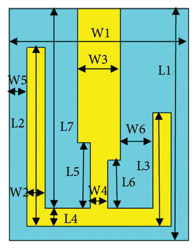
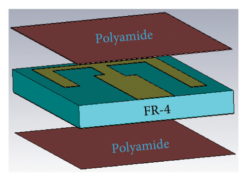
| Parameter (width) | Value (mm) | Parameter (length) | Value (mm) |
|---|---|---|---|
| W1 | 10 | L1 | 13 |
| W2 | 1 | L2 | 9.8 |
| W3 | 2.4 | L3 | 6.35 |
| W4 | 1 | L4 | 1 |
| W5 | 0.9 | L5 | 3.7 |
| W6 | 1.8 | L6 | 2.7 |
| — | — | L7 | 11.2 |
2.2. Design of Brain Phantom
To investigate the performances of the proposed antenna, a numerical brain phantom of seven layers is designed in CST [29, 30]. The seven layers are skin, fat, cortical bone, dura, cerebrospinal fluid (CSF), gray matter, and white matter, which possess a total dimension of 100 × 100 × 72.2 mm3 as shown in Figure 2. The antenna is placed in between the cortical bone and the dura layer of the seven-layer brain model. The tissue electrical properties of the seven layers are listed in Table 2 [30, 31].
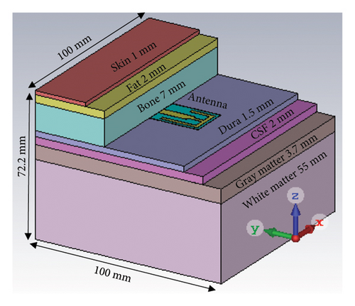
| Tissues | Relative permittivity | Loss tangent | ||
|---|---|---|---|---|
| 2.4 GHz | 4.8 GHz | 2.4 GHz | 4.8 GHz | |
| Skin | 42.923 | 39.858 | 0.273 | 0.319 |
| Fat | 5.285 | 5.048 | 0.145 | 0.171 |
| Cortical bone | 11.410 | 10.135 | 0.252 | 0.338 |
| Dura | 42.099 | 39.106 | 0.292 | 0.326 |
| CSF | 66.319 | 62.316 | 0.385 | 0.379 |
| Gray matter | 48.994 | 45.433 | 0.271 | 0.320 |
| White matter | 36.226 | 33.65 | 0.246 | 0.301 |
2.3. Design Evolution
-
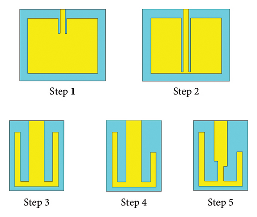
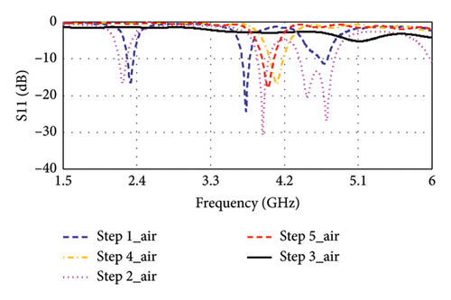
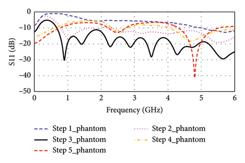
Step 1: In Step 1, as shown in Figure 3, a rectangular-shaped patch antenna is designed using the transmission line (TL) method [32]. The calculated substrate’s dimension (length × width × thickness) is found to be 39 × 47 × 1.5 mm3 for a targeted resonance frequency of 2.4 GHz in free space. Thereafter, the model is simulated in CST for performance evaluation. Figure 4(a) shows the simulated return loss in free space, where the resonance frequency is found to be 2.32 GHz, and two additional bands of 3.73 and 4.68 GHz are observed. The antenna is then tested in a seven-layer brain phantom, where it does not exhibit significant resonance, as shown in Figure 4(b).
-
Step 2: In Step 2, as illustrated in Figure 3, the length of the antenna’s inset-fed TL is increased to extend the electric path, which is necessary for antenna miniaturization. In this case, the antenna resonates at multiple frequencies of 2.22, 3.94, 4.48, and 4.71 GHz in free space, as depicted in Figure 4(a). Conversely, as shown in Figure 4(b), it resonates at dual bands of 1.05 and 5.50 GHz in phantom condition.
-
Step 3: In Step 3, the gaps between the patch and inset-fed TL are increased to further lengthen the electric path. Now, it appears as E-shaped featuring four arms. This antenna does not show any significant resonance in free space, as depicted in Figure 4(a). However, in the brain-implant condition, the antenna exhibits multiband and wide bandwidth characteristics, as shown in Figure 4(b).
-
Step 4: In Step 4, as indicated in Figure 3, the E-shaped structure is miniaturized to dimensions of 13 × 10 × 1.5 mm3 through parametric sweep and optimization of the four arms using the CST tool until it closely approaches the desired frequency band. The antenna resonates at 4.10 GHz in free space, while it resonates at 2.53 and 4.71 GHz in a seven-layer brain phantom.
-
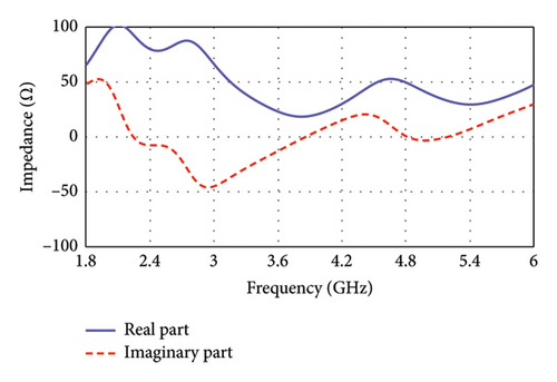
Step 5: Step 5 is considered for fine-tuning of the resonance condition. Here, as shown in Figure 3, the antenna’s TL becomes narrow in a zigzag manner where connecting to the patch. Now, the antenna resonates at 4.0 GHz in free space, as depicted in Figure 4(a), and at dual bands of 2.47 and 4.8 GHz in the seven-layer brain phantom, as shown in Figure 4(b). This proposed antenna exhibits impedance of 49.49 + j0.69 Ω at 4.8 GHz, although the impedance at 2.47 GHz is found to be (78.43–j7.55) Ω, as illustrated in Figure 5.
2.4. Parametric Analysis
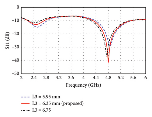
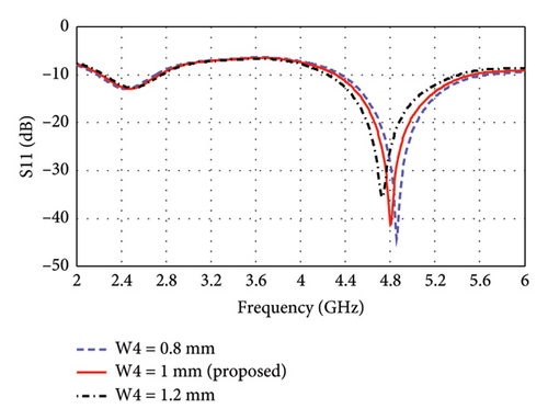
The parametric analysis of the E-shaped antenna is carried out to evaluate its fabrication tolerance and to optimize the geometry. The effect of variation of length on the reflection coefficients is shown in Figures 6(a), 6(b), 6(c), 6(d), 6(e). The resonance frequencies exhibit minimal shifts, while the bandwidth of each mode remains within the proposed bands. Similarly, the effects of width on reflection coefficients are shown in Figures 6(f), 6(g), 6(h). The antenna exhibits more consistent performance in these cases, as the resonance modes and reflection coefficients remain very similar.

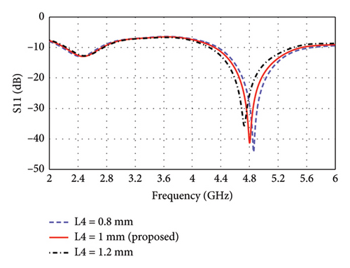
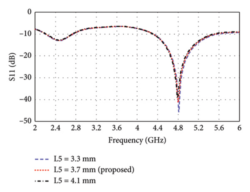

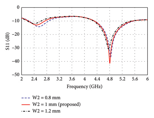
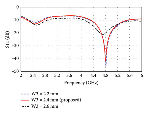
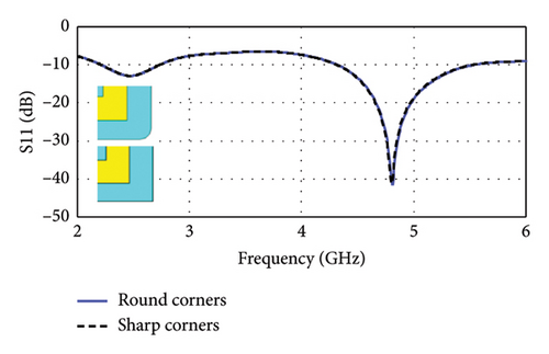
To enhance biocompatibility and minimize potential tissue damage, the sharp corners of the 13 × 10 mm2 antenna substrate are rounded by introducing a 0.5-mm radius curvature. The rounding is applied such that the center of each rounded corner is located at (±4.5, ±6), where the center of the substrate is taken as the reference point (0, 0). This modification ensures a smoother edge transition while maintaining the structural and EM integrity of the antenna. EM simulations demonstrated that this adjustment had a negligible effect on the reflection coefficients, as illustrated in Figure 7, confirming that the antenna’s impedance matching and resonance characteristics remained unaffected.
2.5. Antenna Equivalent Circuit
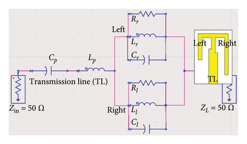
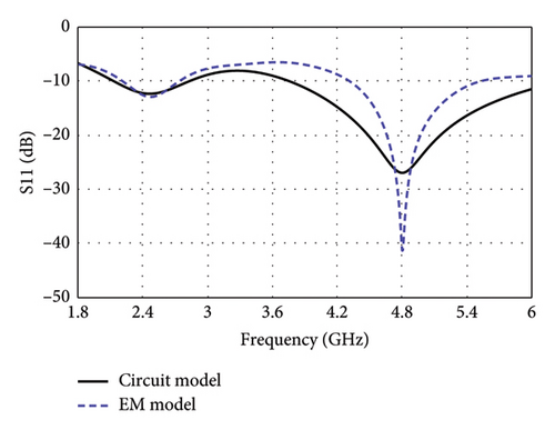
Figure 8(a) illustrates the equivalent circuit of the proposed antenna, modeling the electrical behavior of the E-shaped patch in the lossy environment of the human brain. The TL feed of the antenna is modeled with a series LpCp network, comprising an inductor (Lp = 1.82 nH) and capacitor (Cp = 0.98 pF), which captures the impedance characteristics of the feed. The right and left arms, positioned parallel to the central TL, are presented by parallel RLC networks. The right arm comprises of Rr = 390 Ω, Lr = 2 nH, and Cr = 2.07 pF, while the left arm features Rl = 380 Ω, Ll = 1.8 nH, and Cl = 0.61 pF. In both RLC networks, the internal resistive losses of the inductors are found to be 15 Ω and 5 Ω for the right and left arms, respectively. The interaction among the circuit components of each of the central, left, and right arms contribute to resonating at dual bands. The combined effects of these components also determine the antenna’s overall impedance and radiation behavior. The input (Zin) and output impedance (ZL) of the circuit is set to 50 Ω ensuring near-perfect impedance matching with values of 49.49 + j0.69 Ω at 4.8 GHz. Although the impedance at 2.47 GHz is found to be 78.43–j7.55 Ω in CST simulations, setting the load impedance to 50 Ω facilitates effective signal transfer and aligns with standard RF design practices.
3. Results and Discussions
3.1. Antenna Performances in Brain Phantom
3.1.1. Simulation Results
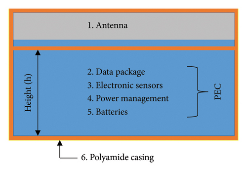
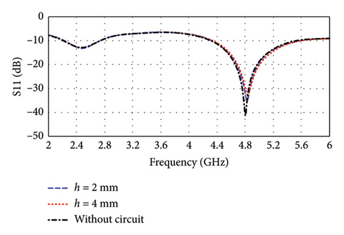
The implantable devices consist mainly of an antenna, data package, sensors, power management, batteries, and IMD casing, as shown in Figure 9(a). Therefore, to assess the system-level performance of the proposed antenna, a perfect electric conductor (PEC) material is placed under the antenna as an equivalent to these integrated components [1, 26, 28]. Additionally, antenna ground is covered with biocompatible polyamide material of 0.005 mm thickness to keep the antenna detached from PEC. Subsequently, the entire IMD is encapsulated with same polyamide material. To analyze the effect of various system-level integration, various heights (h) of PEC are considered under the proposed antenna. According to Figure 9(b), the resonance frequencies are found to be 2.47 and 4.8 GHz without considering the circuit (h = 0 mm) in case of brain implantation, which is not significantly affected by the PEC layer. The resonance frequencies remain almost same when PEC heights are varied within 2–4 mm. The corresponding return losses (|S11|) are −12.90 and −41.29 dB, respectively, which are not significantly affected also. The bandwidths of the implantable antenna are found to be 524 MHz (21.2%) and 1213 MHz (25.27%) at 2.47 and 4.8 GHz, respectively. These high bandwidths are essential for supporting its intended functionality.
Designing an antenna with the desired radiation pattern and directivity poses challenges for antenna engineers. As depicted in Figure 10(a), the proposed antenna demonstrates effective performance within a seven-layer brain phantom, exhibiting a directive radiation pattern with minimal fields on the backside. The side-lobe levels in the E-plane and H-plane are noted as −12.8 and −8.2 dB at 2.47 GHz, respectively. Such pattern is particularly desirable for brain-implantable devices, as it helps to minimize the heating effect on the backside of the antenna. These low side-lobe levels also contribute to enhance the main lobe magnitude and distribute energy over a broader angular range (wide beam width). The antenna directivity at this band is 4.31 dBi directed outwards the brain. Figure 10(b) shows the radiation pattern at 4.8-GHz band, where the side-lobe levels are found to be 11.8 and 11.1 dB for the E-plane and H-plane, respectively. Additionally, a high directivity of 8.12 dBi is observed at this band. Such directive radiation pattern with high beam width of the proposed antenna will facilitate wider coverage area with less alignment problem confirming robust communication in BMI applications.
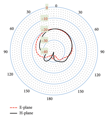
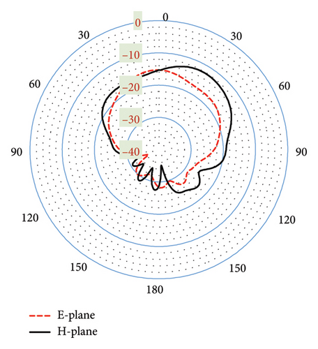
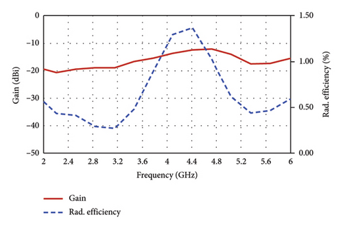
Figure 11 plots the simulated antenna gain and the corresponding radiation efficiency as a function of frequency, which are found to be −19.7 dBi and 0.42% at the 2.47-GHz band, and −12.3% and 0.92% at the 4.8-GHz band, respectively. Typically, implanted antennas exhibit radiation efficiencies of less than 1% due to the influence of tissue on the EM fields [13]. Notably, the radiation efficiency observed in this work exceeds the performance of many implantable antennas as documented in existing literature (e.g. [13, 30]).
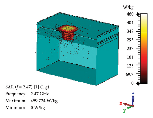
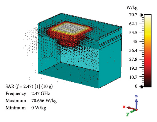
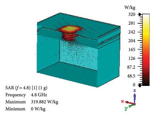
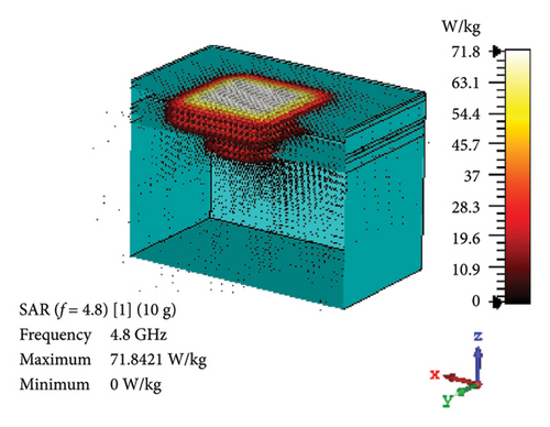
SAR is assessed to quantify the rate at which EM energy is absorbed by brain tissue during exposure. This evaluation is crucial to ensure that RF exposure levels maintain a safety limit, preventing excessive heating and potential harm to the brain tissues. As depicted in Figures 12(a) and 12(b), the proposed antenna yields SAR values of 460 and 70.7 W/kg for 1 g and 10 g tissue standards, respectively, in the band of 2.47 GHz. Likewise, Figures 12(c) and 12(d) illustrate these values at 4.8-GHz band, which are 320 and 71.8 W/kg for 1 and 10 g tissue standards, respectively. Considering the FCC-recommended maximum level of 1.6 W/kg for 1 g tissue standard and 2 W/kg for 10 g tissue standard, the maximum allowable input power for the proposed brain-implant antenna is 3.5 and 28.3 mW, respectively, at 2.47 GHz. Similarly, these values will be 5 and 27.9 mW for the two standards, respectively, at 4.8 GHz.
3.1.2. Antenna Fabrication and Ex Vivo Measurement
The proposed antenna is fabricated on an FR-4 substrate with a thickness of 1.5 mm. The CNC milling machine is used to etch the copper clad from the substrate. Figure 13(a) shows the pictorial view of the fabricated prototype along with the measurement setup. The polyamide superstrate is used to cover the patch and ground to keep away from direct contact among the antenna’s metal parts and human tissues. Then, the fabricated antenna is connected to a connector with 50Ω characteristic impedance for feeding the antenna and RF testing.
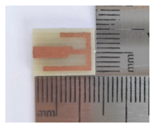
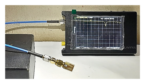
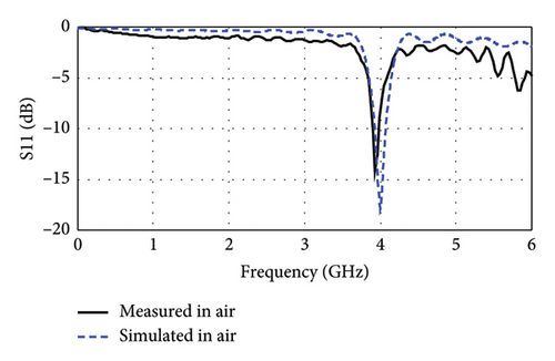
The fabricated antenna is measured in free space before proceeding to ex vivo experiments, as depicted in Figure 13(b). The measurement was done by employing a NanoVNA whose calibration (1.5 kHz–6 GHz, 50Ω) and accuracy were ensured by comparing with standards before the measurement. In free space, as shown in Figure 13(c), the peak resonance is measured at 3.93 GHz with −14.18 dB return loss (|S11|), which are very close to the simulation results (4.0 GHz with −18.07 dB). Such close alignment between the simulation and measurement results in free space indicates promising performance matches also for ex vivo measurements.
To ensure biocompatibility, a thin layer of 0.05-mm biocompatible polyamide material is employed, as shown in Figure 14(a). This layer is bonded to both the patch and ground planes to fully encapsulate the antenna structure, as illustrated in Figure 14(b). Additionally, the connector and metallic section of the coaxial cable connected to the vector network analyzer (VNA) are also encapsulated to prevent any potential short-circuiting during measurements. Considering the challenges of technical and legal issues required for in vitro measurement, this study considers ex vivo measurements following some conventional works [5, 28]. Accordingly, the measurements are conducted with a sheep’s brain as captured in Figures 15(a) and 15(b). The sheep’s brain used in this study was sourced from a local market and obtained from a deceased sheep.
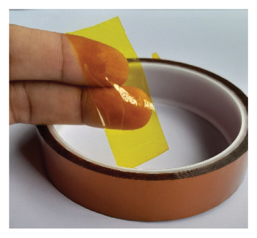

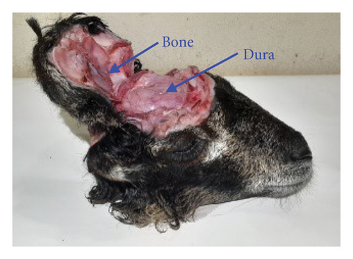
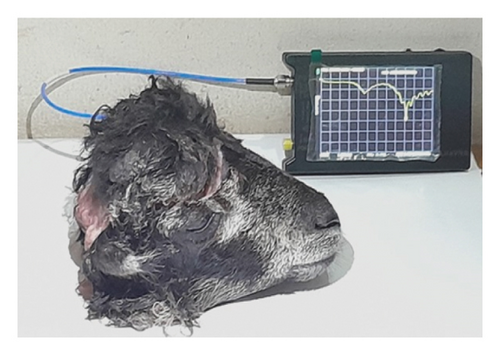
Figure 16(a) illustrates the simulated and measured return loss (|S11|) of the proposed antenna in a sheep’s brain. The peak resonance frequencies of the antenna are measured at 2.34 GHz with a −13.85 dB return loss (|S11|) and at 4.56 GHz with a −40.62 dB return loss (|S11|) in the ex vivo measurement. In contrast, the simulation results show resonance frequencies at 2.47 and 4.8 GHz with return loss (|S11|) of −12.90 and −41.29 dB, respectively. The slight discrepancies between the simulated and measured results can be attributed to the differences in the electrical properties of human and sheep brains, as well as the irregular shape of the cortical bone. However, such good conformity between the simulation and the experimental results justifies satisfactory performance in case of practical applications.
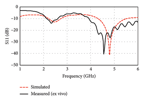
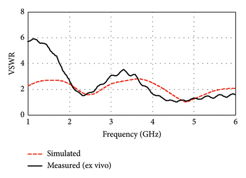
Figure 16(b) illustrates the measured VSWR and compares it with the simulated result. The measured VSWR is found to be 1.5 and 1.02 for the 2.34- and 4.56-GHz bands, respectively, while the simulated VSWR values are 1.6 and 1.02 for the 2.47 and 4.8 GHz. The ideal VSWR value is typically 1.0, indicating a perfect match, although the values in the range of 1–2 are generally acceptable in practice. These results suggest that the antenna has good impedance matching and is likely to meet the desired performance criteria in its intended applications.
3.2. Antenna Performances Within a 3-Layer Tissue Phantom
3.2.1. Simulation Results
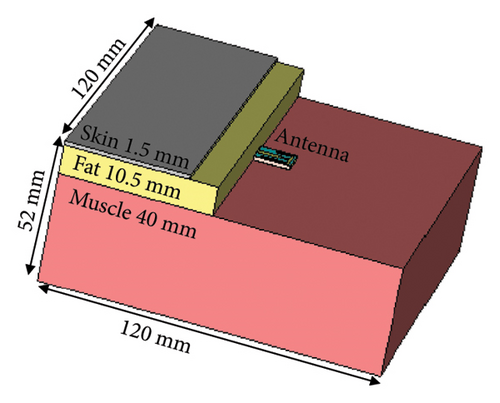
Along with the brain-implant applications, the proposed antenna is also suitable for the skin-implantable applications. To demonstrate its performance for such case, the antenna is tested within the three layers of human tissue phantom (skin, fat, and muscle), which is shown in Figure 17. The thickness of the skin, fat, and muscle layers are taken as 1.5, 10.5, and 40 mm, respectively [33]. As shown in the figure, the antenna is positioned between the fat and muscle, and comparatively, a large phantom volume of 120 × 120 × 52 mm3 is considered for the simulation. The electrical properties (permittivity and conductivity) considered for the three layers are listed in Table 3, sourced from the FCC website as given for the group of average adult (age > 25 years) [35].
| Tissue | Frequency (GHz) | Permittivity (F/m) | Electric conductivity (S/m) |
|---|---|---|---|
| Skin | 3.16 | 41.905144 | 2.059120 |
| 6.00 | 38.377537 | 4.542172 | |
| Fat | 3.16 | 5.207793 | 0.137974 |
| 6.00 | 4.936673 | 0.306234 | |
| Muscle | 3.16 | 53.423027 | 2.474248 |
| 6.00 | 49.188145 | 5.702181 | |
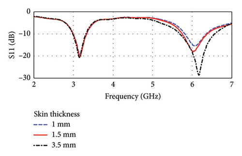
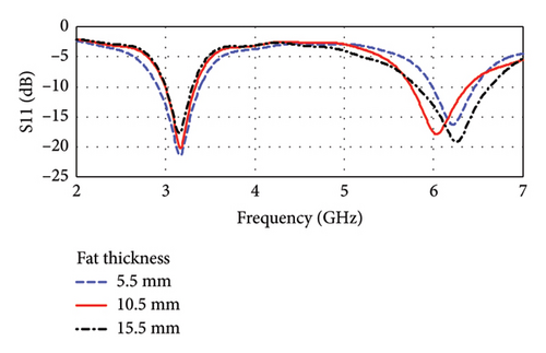
The antenna is found to be resonant at dual bands of 3.16 and 6.0 GHz, which is shown in Figures 18(a) and 18(b). The frequencies fall within the UWB band of 3.1–10.6 GHz. The corresponding return losses (|S11|) are found to be −20.27 and −17.8 dB, and the bandwidths are 338.12 MHz (10.7%) and 631.80 MHz (10.53%), respectively, considering a skin thickness of 1.5 mm and fat thickness of 10.5 mm. Figures 18(a) and 18(b) also demonstrate the influence of the variation of skin and fat thicknesses on the antenna resonance. Such variations in the thickness of skin and fat tissues are common among individuals. As shown in figures, the skin thickness varies from 1.0 to 3.5 mm, and the fat thickness varies from 5.5 to 15.5 mm. It is found that the shift of resonance frequencies lies within the bandwidths of each respective band having sufficient (< −10 dB) values of |S11|. However, the overall performance will not have significant disturbance even when the skin and fat thicknesses are varied by 30%–50%.
Antenna performances may also be altered with the variation of tissue properties caused by the physiological differences among individuals, including factors such as health, age, and other variables. To study such factors, the individuals are categorized into three groups: average child (age > 5 years), average adult (age > 25 years), and average elderly (age > 60) [34]. Tables 4 and 5 present the electrical properties of skin, fat, and muscle for the other two groups of average child and average elderly, respectively. Since these data cannot be found directly in the literature, they are obtained by some adjustment (70%–110%) with the values of average adults. The amount of adjustment and their reasons in terms of physiological characteristics are also explained on the tables. However, these considered variations of the electrical properties for skin, fat, and muscle cover the properties of most of the tissues of different parts of the body [35]. Such an investigation with a large variation of antenna environments ensures the flexible application of the proposed antenna on different positions on the body. Figure 19 illustrates the resonance properties of the antenna for three groups of individuals. As depicted in this figure, the resonance frequencies are found at 3.16 and 6 GHz for the average adult (age > 25 years), and these are found at 3.31 and 6.33 GHz for the average child (age > 5 years), and at 3.24 and 6.20 GHz for the average elderly (age > 60 years) groups.
| Tissue layer | Freq. | Adjusted permittivity | Adjusted conductivity (S/m) | Cause of adjustment |
|---|---|---|---|---|
| Skin | 3.16 | 41.905144 ∗ 0.9 ≈ 37.7146296 | 2.059120 ∗ 1.1 ≈ 2.265032 | The decrease in permittivity in children is attributed to the lower thickness of the epidermal layer compared to adults, resulting in a lower capacitance per unit area. Besides, the increase in conductivity due to increase of hydration or blood flow [36] |
| 6.00 | 38.377537 ∗ 0.9 ≈ 34.5397833 | 4.542172 ∗ 1.1 ≈ 4.9963892 | ||
| Fat | 3.16 | 5.207793 ∗ 0.8 ≈ 4.1662344 | 0.137974 ∗ 0.8 ≈ 0.1103792 | The decrease in permittivity and conductivity values in children is due to their lower adipose tissue content compared to adults [37] |
| 6.00 | 4.936673 ∗ 0.8 ≈ 3.9493384 | 0.306234 ∗ 0.8 ≈ 0.2449872 | ||
| Muscle | 3.16 | 53.423027 ∗ 0.7 ≈ 37.3961189 | 2.474248 ∗ 0.7 ≈ 1.7319736 | The decreased permittivity and conductivity in children’s muscle tissue result from their lower muscle mass compared to adults [38], which result in reduced ion concentration and mobility in the muscle |
| 6.00 | 49.188145 ∗ 0.7 ≈ 34.4317015 | 5.702181 ∗ 0.7 ≈ 3.9915267 | ||
| Tissue layer | Freq. | Adjusted permittivity | Adjusted conductivity (S/m) | Cause of adjustment |
|---|---|---|---|---|
| Skin | 3.16 | 41.905144 ∗ 1.1 ≈ 46.0956584 | 2.059120 ∗ 0.9 ≈ 1.853208 | The increase in permittivity in elderly skin primarily stems from the thinning of the dermis and epidermis layers, resulting in a higher relative water content and increased ion mobility within the tissue. The slight decrease in conductivity is attributed to slowed blood flow and reduced ion concentration, which are consequences of age-related alterations [36] |
| 6.00 | 38.377537 ∗ 1.1 ≈ 42.2152907 | 4.542172 ∗ 0.9 ≈ 4.0879548 | ||
| Fat | 3.16 | 5.207793 ∗ 0.9 ≈ 4.6860137 | 0.137974 ∗ 0.9 ≈ 0.1241766 | The lower permittivity and conductivity values are due to their changes in fat distribution and composition compared to adults [39] |
| 6.00 | 4.936673 ∗ 0.9 ≈ 4.4430057 | 0.306234 ∗ 0.9 ≈ 0.2756106 | ||
| Muscle | 3.16 | 53.423027 ∗ 0.8 ≈ 42.7384216 | 2.474248 ∗ 0.8 ≈ 1.9793984 | The decrease in permittivity and conductivity can be attributed to reduced muscle mass (atrophy) and altered tissue composition [40] |
| 6.00 | 49.188145 ∗ 0.8 ≈ 39.350516 | 5.702181 ∗ 0.8 ≈ 4.5617448 | ||
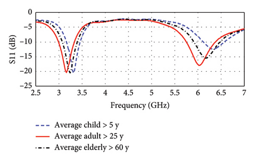
It is evident that the resonance frequencies for all age groups fall within the UWB band, and their shifts remain within the bandwidth of each respective band. The change in the corresponding return losses is also insignificant. This indicates that the proposed antenna will be equally applicable (remain within UWB) for a large variation of tissue properties.
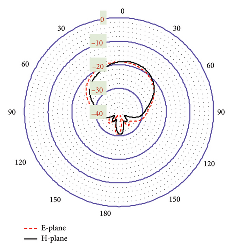
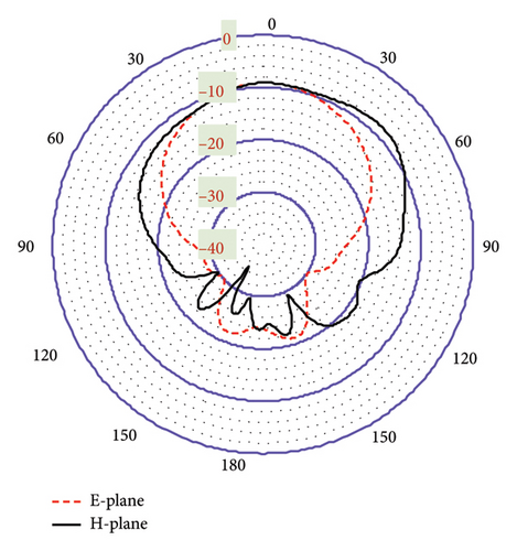
As shown in Figures 20(a) and 20(b), the proposed antenna exhibits a directive radiation pattern at both 3.16-GHz and 6-GHz bands. Their E-plane and H-plane radiation patterns are almost similar to being omnidirectional with minimal fields on the backside. This polar radiation pattern in Figure 20(a) shows the simulated gain of −18.7 dBi at 3.16 GHz. In Figure 20(b), though there exists a small side lobe for both planes, it provides a high gain of −9.12 dBi at the 6-GHz band. Furthermore, the antenna directivity is observed at 6.86 and 6.29 dBi in the 3.16- and 6-GHz bands, respectively, both directed toward off-body direction as desired for biotelemetry applications. In this case, within the three-layer tissue model, the proposed antenna exhibits better gain and directivity compared to the seven-layer brain phantom.
3.2.2. Ex Vivo Measurement Within 3-Layer Tissue Environment
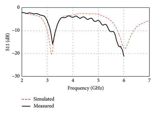
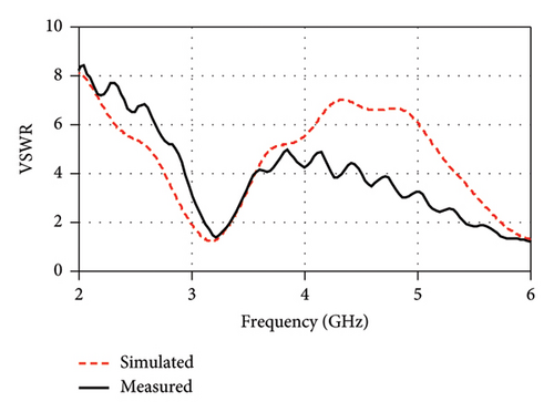
For the ex vivo measurement of the proposed antenna, a three-layer tissue environment consisting of chicken’s skin, beef, and fat was utilized as depicted in Figure 20. The comparison between the simulated and measured performance is illustrated in Figure 21.
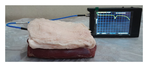
As shown in Figure 22(a), the measured resonance frequency is observed at 3.21 GHz with a return loss (|S11|) of −15.7 dB, which are in close agreement with the corresponding simulation results of 3.16 GHz with a −20.27 dB return loss (|S11|). Another peak resonance is measured at 6 GHz with a return loss (|S11|) of −21.24 dB. As illustrated in Figure 22(b), the measured VSWR is also found to be very small (1.39 at 3.21 GHz and 1.19 at 6 GHz) and in close agreement with the simulation results (1.21 at 3.16 and 1.29 at 6 GHz). The measured curve is shown up to 6 GHz due to the limited range of the used VNA. However, due to the inaccessibility of the anechoic chamber, this research is limited to the measurements of S parameters only. Consequently, the study relies on simulation for comprehensive assessments of the radiation pattern and gain analysis.
3.3. Link-Budget Calculations
To establish a reliable wireless communication between an IMD and an external device (a controlling or monitoring device), the typical link-budget analysis is presented in Table 6. This study mainly focuses on the path loss, considering it as a dominating factor, and calculated it using equations (3)–(5) [26].
| Link budget | Specifications |
|---|---|
| Link margin (LM) calculation LM (dB) = CL–RL (3) |
|
|
|
| Required link (RL) calculation RL (dB) = Eb/N0 + 10 log10 Br − Gc + Gd (5) |
|
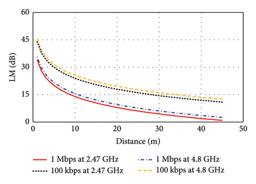
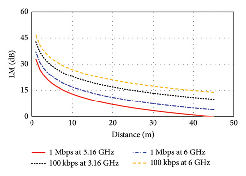
The input power of the proposed antenna is considered as Pt = 100 μW corresponding to Refs. [26, 28]. This input power is much smaller than the allowed maximum input power, which is obtained considering SAR limits recommended by the FCC. Hence, high SAR poses no significant challenge for the proposed antenna when implanted in either brain- or skin-implant applications. To estimate this link budget, a bit rate (Br) of 1 Mbps and 100 kbps are considered in this study to obtain the maximum link length for low-to high-data-rate applications. As depicted in Figure 23(a), the link margin (LM) versus transmitter-to-receiver distance is illustrated for the brain-implant condition. Considering the LM of 15 dB for reliable communications, the communication distance is found to be 9 m at 2.47 GHz for the data rate of 1 Mbps, which can be extended to 28 m for the lower data rate of 100 kbps. At the 4.8-GHz band, the communication distance increases to 11 m at 1 Mbps and to 35 m at 100 kbps. Similarly, Figure 23(b) shows the LM versus transmitter-to-receiver distance for the skin-implant condition. At the 3.16-GHz band, the distances are 8 m at 1 Mbps and 24 m at 100 kbps. At the 6-GHz band, the communication distance reaches 13 m at 1 Mbps and 39 m at 100 kbps. These results demonstrate that higher frequencies generally allow for longer communication distances, especially at lower data rates.
3.4. Comparison With Existing Literature
The antenna performance of this work is compared with several recently published notable studies, as summarized in Table 7. The proposed antenna is compact in size compared to [18, 20, 24, 41], which is crucial for ensuring patient comfort. While some of the designs [16, 17, 19, 21–23, 25] are little compact than this work, the proposed antenna leads by its significantly higher bandwidth and comparable gain. A very few designs [42] have been found in the literature which are very compact and at the same time demonstrated excellent performance. However, they are limited by either very specific application or single-band operation or both. On the other hand, the proposed design demonstrates versatile applications for both brain- and skin-implantable devices with very small detuning effect caused by the variation of individuals (age, sex). Its dual-band functionality further supports implantable devices by enabling wake-up signals and high data rate biotelemetry. Considering all these multiple features, the proposed antenna is compact while exhibiting comparatively higher bandwidth and gain. Although the antenna demonstrates a relatively high SAR, it remains within the safety limit, and lower than many other designs [20, 25, 42] in the literature.
| Ref./year | Antenna volume (mm3) | Implant tissue | Frequency (MHz) | Tissue volume (mm3) | Implant depth (mm) | Return loss (|S11|) dB | Impedance BW (%) | Gain (dBi) | SAR (W/Kg) | |
|---|---|---|---|---|---|---|---|---|---|---|
| 1 g | 10 g | |||||||||
| [16]/2023 | 10 × 10 × 0.375 | Muscle | 3500 | 60 × 60 × 34 | 7 | −25 | — | −14.2 | 0.529 | — |
| [17]/2024 | π × 42 × 0.889 | Small intestine | 2450 | π × 202 × 60 | 30 | −35 | 4.9 | −26.7 | 216 | — |
| [18]/2015 | 24 × 10 × 0.95 | Head (skull) | 4000 | 125 × 87 × 12.5 | 2 | −18 | 10 | −8 | 53 | 17 |
| [19]/2019 | 10 × 10 × 1.5 | Brain | 2465 | 100 × 100 × 72.2 | 10 | −41 | 3.2 | −25 | — | — |
| [20]/2019 | 20 × 20 × 0.8 | Brain | 400 | Piglet’s head | 14 | −48 | — | — | 623.19 | 92.39 |
| [21]/2020 | π × 5 × 5 × 3.2 | Muscle | 610 | 50 × 50 × 50 | 50 | −19 | 1.2 | −20 | — | — |
| [22]/2021 | 10.5 × 10.5 × 1.27 | Skin | 2410 | 100 × 100 × 100 | 3 | −36 | 8.5 | −22.93 | 347.08 | 66.55 |
| [23]/2023 | 10 × 10 × 2.54 | Skin | 2450 | 60 × 60 × 9.28 | 3 | −34 | 4.8 | −18.41 | 402 | — |
| [24]/2023 | 17.2 × 14.8 × 0.254 | Skin | 400 | 200 × 200 × 200 | 2 | −33 | 5.75 | −42.97 | — | — |
| 2450 | −17 | 7.76 | −17 | — | — | |||||
| [25]/2023 | 10 × 10 × 1.27 | Skin | 1400 | 100 × 100 × 50 | 4 | −27 | 3.57 | −37 | 215 | 38.7 |
| 2400 | −31 | 6.37 | −21 | 565 | 94.6 | |||||
| [41]/2024 | 15.5 × 9 × 1.27 | Brain | 2450 | 120 × 80 × 60 | 4 | −45 | 30.67 | −28.3 | 368 | 45.2 |
| [42]/2025 | 5 × 5 × 1.27 | Skin | 1400 | 100 × 100 × 50 | 4 | −28 | 18.1 | −30.6 | 610 | 64.4 |
| 2420 | −28.5 | 18.29 | −32.4 | 625 | 66.1 | |||||
| This work | 13 × 10 × 1.6 | Brain | 2470 | 100 × 100 × 72.2 | 10 | −12.90 | 21.21 | −19.7 | 460 | 70.7 |
| 4800 | −41.29 | 25.27 | −12.3 | 320 | 71.8 | |||||
| Skin | 3160 | 120 × 120 × 40 | 12 | −20.27 | 10.70 | −18.7 | 500 | 66.6 | ||
| 6000 | −17.9 | 10.53 | −9.12 | 257 | 59.8 | |||||
4. Conclusion
In this research, a compact E-shaped antenna was designed to operate in dual bands for two different environments of brain implant and skin tissue implant, respectively. The antenna was designed on an FR-4 substrate and encapsulated with biocompatible polyamide, resulting in overall dimensions of 13 × 10 × 1.6 mm3. When the antenna was placed between the cortical bone and dura layer of the human brain, it resonated at dual bands of 2.47 and 4.8 GHz, exhibiting impedance bandwidths and gains of 21.21% and −19.7 dBi, and 25.27% and 12.3 dBi, respectively. In the case of skin tissue-implant model, it also resonated at dual bands of 3.16 and 6 GHz with impedance bandwidths and gains of 10.7% and −18.7 dBi, and 10.53% and 9.12 dBi, respectively. The performance of the designed antenna (when skin implanted) was examined across different age groups, showing that the large bandwidth keeps the antenna performance stable even when detuning occurs with the varying physiological conditions. Furthermore, the LM analysis demonstrated that the transmitter antenna can establish effective communication with the receiver antenna 8–35 m away at a bit rate of 1 Mbps to 100 kbps, respectively. Finally, the antenna was fabricated and measured in a sheep’s brain and in some tissues of chickens and cow. The measured |S11| parameters and VSWR were found to be in close agreement with the simulated results, indicating their potential in desired applications.
Conflicts of Interest
The authors declare no conflicts of interest.
Funding
No funding was received for this manuscript.
Open Research
Data Availability Statement
Data sharing is not applicable to this article as no new data were created or analyzed in this study.


