General Modeling for Space Robot Proximity Relative Motion by Using Dual Operator With Hybrid Coordinates
Abstract
With the increasing demand for space missions, task robots have evolved from rigid bodies to rigid-flexible coupling in close-range approach missions, such as flexible module in-orbit assembly missions and flexible spacecraft formation missions proposed in recent years. This poses a challenge to the dynamic modeling of space proximity tasks that are more concise, efficient, and have engineering practicality. In this paper, a six-degree-of-freedom representation of space robot proximity relative dynamics is developed by using the algebra of dual numbers, whether the space robot is a rigid body or a rigid-flexible coupling system. The main work of this paper lies in the following three aspects: First, this paper develops a six-dimensional screw representation of dual number–based general dynamics that allows model parameters (dual inertia operator) to be directly matched with space robot engineering parameters (mass and moment of inertia) to replace its classical three-dimensional motor form. This work improves the convenience of the engineering application of the general model. Second, by combining hybrid coordinate modeling methods with dual algebra, the general expression is extended from the motion of a rigid body to a flexible body; on this basis, the integrated dynamic model of the rigid-flexible coupling space robot is developed. This effort solves the problem of compact representation and computational efficiency of relative dynamic models between two rigid-flexible coupling space robots. Third, the derivative rule of a space robot with time-varying configuration is provided; this work enables the general model to be applied to certain specific scenarios, such as space robot proximity missions under the premise of rotating solar panels, rotating optical lenses, or other rotating structures. Based on the above relative dynamics, a PD controller is adopted, and the successful application of the proposed models is verified.
1. Introduction
In the 19th century, Clifford first introduced dual numbers in Ref. [1]. At first, the application of dual numbers to rigid body kinematics was subsequently generalized by Study and Brodsky and Shoham in their principle of transference [2, 3]. In 1999, the general representation of rigid body dynamics was provided by Brodsky and Shoham by using motor transformation rules and a dual inertia operator [3]. In Ref. [3], the dual number–based dynamic equations are represented in Newton–Euler form. Compared with the classical Newton–Euler equation, the main advantage of the dual number–based equation is the compactness of representation. That is, the classical dynamic models are derived using two equations: one that accounts for the three degree-of-freedom (DOF) translational dynamics and the other that captures the three-DOF rotational dynamics. The dynamic model based on dual numbers describes the six-DOF motion of a rigid body with one equation by using a three-dimensional dual motor; therefore, it is defined as an integrated model [4–6]. Wang et al. [7] extended the above-integrated model to describe the attitude and orbital motion of a rigid space robot and further proposed a three-dimensional motor model of space robot proximity six-DOF relative motion. However, the dynamic equation derived by Wang et al. [7] is a centroid-relative dynamic model instead of a general model; that is, the origin of the reference coordinate system is set at the center-of-mass (COM) of a space robot and can describe the relative motion between the COM of rigid space robots. Wang et al. [8, 9] further investigated the control methods of space robot formation flying (SFF) missions based on the centroid relative dynamic model. This model was followed to solve the guidance, navigation, and control (GNC) problems of the space robot proximity cooperative missions, such as SFF, on-orbit assembly, and space debris capture, in Refs. [10–18].
However, the integrated model proposed in Ref. [3] is represented as a three-dimensional motor form, whose dual inertia operator is related to the moment of inertia relative to the arbitrary axis of the rigid body. In aerospace engineering, the space robot’s moment of inertia is always given relative to the principal axis of inertia. This leads to a problem where the parameters of the general model cannot be directly obtained with engineering parameters. The extended dynamic equation proposed in Ref. [7] is a model for special operating conditions and does not have universal applicability. In addition, it is not intuitive to express the six-DOF relative motion as a three-dimensional motor form for scholars without a foundation in studying dual algebra, which is not conducive to the promotion and application of the model. This paper proposes the six-dimensional screw representation of dual vector, dual inertia, and dual force to replace its three-dimensional motor form and develops a six-dimensional screw representation of dual number–based dynamics to describe the six-DOF motion of a rigid space robot. Compared with the dual motor form, the six-dimensional screw representation allows the model parameter (dual inertia operator) to be directly matched with space robot engineering parameters (mass and moment of inertia), which greatly improves the convenience of the engineering application of the general model.
In recent years, there has been an attempt to apply dual numbers to rigid-flexible coupling space robot dynamics [19]. However, in the above investigation, the integrated model was expressed as a simple symbol transformation of classical Newton–Euler equations, which does not reflect the advantages of the dual number in physical description and mathematical computation. The recently introduced dual momentum of a flexible body [20, 21] suggested a solution to this problem by developing a dual vector, dual momentum, dual inertia operator, dual coupling coefficient operator, and dual-modal coordinates of a flexible body. On this basis, the centroid relative dynamic model between the rigid-flexible coupling space robot was derived from Zhang et al.’s paper [20–22]. This paper expands on the results reported in Refs. [20–22] and gives a more general expression for the relative dynamic equation. The relative dynamic equations between the rigid-flexible coupling space robot with a time-varying configuration are further derived. This relative dynamic model can solve the description problem of relative motion between space robots with rotating flexible components, such as solar panels.
In summary, this paper mainly focuses on the general dynamic modeling for proximity relative motion of space robots. In the first part, this paper combines the advantage of the results reported in Brodsky and Shoham [3] and Wang et al. [7] and proposes a six-dimensional screw representation of dual number–based general dynamics for the proximity relative motion of space robots. Then, the six-dimensional screw representation is expanded to the general relative dynamic modeling between two rigid-flexible space robots, preserving the advantages of compactness and computational efficiency of the dual number. In addition, the application of the general dynamics to the time-varying configuration space robot is explored in this paper.
The paper is organized as follows. In Section 2, the general model between rigid space robots is provided. Section 3 proposes the general model between rigid-flexible coupling space robots. Section 4 develops the integrated dynamics between space robots with time-varying configurations. Section 5 provides a PD controller. Numerical simulation is presented in Section 6 to verify the dynamics developed in this paper. Finally, the paper is concluded in Section 7.
2. General Representation of Six-DOF Relative Motion Between Rigid Space Robot
Equation (2) can be directly solved through screw operations, making it more suitable for engineering promotion. However, the six-dimensional screw representation provided by Wang et al. is the centroid dynamic equation that replaces rigid body dynamics with the motion of the COM, not a general model. This paper develops a six-dimensional screw general dynamic model instead of Brodsky and Shoham’s three-dimensional motor representation and Wang et al.’s centroid dynamic equation.
Remark 1. In a dual number–based model, the motion of a rigid space robot is equivalent to that of a system of particles rather than a single COM. That is, in the modeling process, we not only care about the mass of the space robot but also the size of the space robot. Space robot size is an important parameter for dynamics modeling. Since the space robot has volume, the origin of the body-fixed coordinate system (BFCS) of the rigid space robot can be set at an arbitrary point on the space robot, not necessarily the point of COM. The general representation of rigid space robot dynamics enables the calculation of the dual vector and the dual force with respect to the BFCS, in which the origin is set at an arbitrary point on the space robot.
Remark 2. The derivation of the dynamic equation in this paper is carried out with respect to the BFCS. That is, the representation of the space robot rotational equation and the translational equation are unified not only in the same mathematical framework but also in the same reference coordinate system.
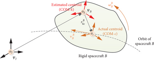
As shown in Figure 1, in this section, the following two coordinate systems are used: ΨI, the standard earth-centered, inertial, Cartesian right-hand coordinate system. ΨB, the BFCS of a rigid space robot B, with its origin in an arbitrary point, k, of the space robot, and axes pointing along the principal axes of inertia. The following notations are employed: denotes the components of x expressed in the BFCS of space robot B with its origin in an arbitrary point k.
2.1. General Representation of a Rigid Particle by Using Six-Dimensional Dual Screw
A rigid space robot is equivalent to a system of particles. As shown in Figure 1, assuming the rigid space robot B is a system composed of N particles with equal mass. In order to clearly express the six-dimensional screw form of dual vector and dual momentum, we start our discussion by deriving the dual velocity and dual momentum of a rigid particle relative to the COM of a rigid space robot B. That is, in the next derivation, we set the state quantities of COM of space robot B as the known parameters, and the state quantities of other particles of the rigid space robot are derived from the above-known parameters.
- 1.
, the attitude angular velocity of space robot B, is defined as the angular velocity of ΨB relative to ΨI in terms of components along the BFCS of space robot B. is used as a known parameter for deriving the dual velocity of rigid particles in this paper.
- 2.
, the orbital velocity of space robot B, is defined as the linear velocity of the COM of space robot B relative to the origin of ΨI in terms of components along the BFCS of space robot B. is used as another known parameter for deriving the dual velocity of rigid particles.
2.2. General Representation of a Rigid Space Robot by Using Six-Dimensional Dual Screw
is represented as a six-dimensional matrix in this paper instead of a three-dimensional matrix proposed in Ref. [3] to describe the six-DOF of a rigid space robot. mB and JB are common parameters in aerospace engineering missions. Therefore, the general representation of the dual momentum of a rigid space robot in a six-dimensional screw form is obtained.
2.3. General Representation of a Rigid Space Robot Dynamics in Newton–Euler Form
The derivation of Equation (19) is carried out with respect to the BFCS of space robot B, as explained in Remark 2. The selection of a reference coordinate system is crucial for derivative operations of Equation (21). This is also the difference between the dual screw dynamics modeling method and the traditional Newton–Euler method. The traditional Newton–Euler equation can use different reference coordinate systems for translational motion and rotational motion. For example, the reference coordinate system for the CW equation is the orbital coordinate system, while the Euler attitude equation uses the BFCS as the reference. The reference coordinate system for the six-DOF motion of the dual screw method must be unified, which reflects the idea of integrated modeling.
denotes the dual force acting on the COM of space robot B.
2.4. General Representation of Relative Dynamics Between Rigid Space Robot
This subsection considers a two-earth-orbiting-space robot proximity cooperative mission, including a leader space robot A and an operator space robot B. In this subsection, a new BFCS of space robot A is adopted. ΨA, the BFCS of a rigid space robot A, with its origin in an arbitrary point, p, of space robot A, and axes pointing along the principal axes of inertia. The following notations are employed: denotes the components of x expressed in the BFCS of space robot A with its origin in an arbitrary point p.
Equation (30) is defined as the centroid relative dynamic equation.
3. General Representation of Six-DOF Relative Motion Between Rigid-Flexible Coupling Space Robot
A typical rigid-flexible coupling space robot consists of a rigid body and a flexible body, as shown in Figure 2. This section uses the same two coordinate systems as Section 2, and the origin of ΨB is set at an arbitrary point, k, in the rigid part of space robot B. In addition, a new coordinate system, floating coordinate system ΨF is used in the derivation of the dynamic model in this section. Ψf, the floating coordinate system of the rigid-flexible space robot B, with its origin in the connection point between the rigid part and flexible part, f, and axes pointing along the principal axes of BFCS.
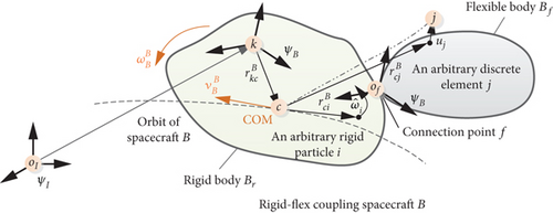
The first challenge of this section is the derivation of the dual momentum of the flexible body by using hybrid coordinates. Since we use dual number representation, the six-dimensional screw expression of vibration motion, a coupling matrix is needed. On this basis, the cross-coupling dynamics between attitude-orbit coupling and rigid-flexible coupling of a rigid-flexible combination space robot are developed. Finally, the relative dynamic equations between rigid-flexible coupling space robots are provided.
3.1. General Representation of a Flexible Body by Using Dual Operator With Hybrid Coordinates
As shown in Figure 2, selecting the flexible body Bf as the object, by using Ψf and ΨB as reference coordinate systems, the dual velocity and dual momentum of Bf are derived with hybrid coordinates.
Considering that the initial three-axis orientation of Ψf coincides with that of ΨB, and there is no relative rotation between the above two coordinate systems. In order to match the rigid body dynamics derived in Section 2, we plan to construct the rigid-flexible coupling dynamics model in ΨB.
Equation (36) is the complete expression of the dual momentum of a discrete finite element j. According to Refs. [23, 24], in order to represent the dual momentum with a hybrid coordinate system, the small deformation assumption needs to be adopted. That is, in Equation (36), is much smaller than and can be ignored in calculations.
Comparing Equation (37) with Equation (11), which represents the dual momentum of a rigid particle, we find that three new items, , , and , are needed to describe six-DOF motion of an arbitrary discrete element of the flexible body.
Two coordinate systems, Ψf and ΨB, are used in Equation (30). Through the above work, the dual momentum of the flexible body Bf is represented in a six-dimensional screw form with hybrid coordinates. Note that, due to the stable configuration of rigid-flexible coupling space robots, Ψf and ΨB always coincide. Therefore, the variables derived in this subsection can be represented in either the floating coordinate system or the BFCS.
3.2. General Representation of Dynamics by Using Dual Operator With Hybrid Coordinates
The vibration function of the rigid-flexible coupling space robot refers to Equation (31) in Ref. [21].
3.3. General Representation of Relative Dynamics by Using Dual Operator With Hybrid Coordinates
Equation (54) is defined as the centroid relative dynamic equation.
4. General Representation of Six-DOF Relative Motion Between Space Robot With Time-Varying Configuration
In Section 3, dynamic equations of rigid-flexible coupling space robots with a stable configuration are developed. The dynamic equations proposed in Section 3 are applicable to the working conditions of space robots in which flexible components are firmly connected with rigid platforms, such as some radar satellites and optical satellites. However, in most cases, there is relative rotation between the flexible component and the rigid platform. For example, solar panels sometimes rotate around the platform, and optical lenses rotate around the platform in some working conditions. In view of the above scenario, it is necessary to develop a six-dimensional screw representation of the six-DOF motion of the rigid-flexible coupling space robot with a time-varying configuration. This section focuses on the above issues.
4.1. General Representation of Space Robot With Time-Varying Configuration
In Equation (55), the attitude angular velocity is represented with respect to the BFCS ΨB.
Comparing with Equation (39), we find that three new items, , , and , are taken to describe the dual momentum of a discrete element.
4.2. General Representation of Dynamics of Space Robot With Time-Varying Configuration
Compared with Equation (46), it can be found that the derivation rule of Equation (69) has changed. For a configuration time-varying system, it is necessary to first solve the derivative of the dual momentum of each subsystem and then perform the sum operation. The operation order cannot be reversed since the dual velocity of each subsystem is different. However, the order of addition and derivation can be reversed for a configuration-stabilized system.
4.3. General Representation of Relative Dynamics of Space Robot With Time-Varying Configuration
5. Dual Number–Based Controller
Controller (74) has achieved good results in proximity collaborative tasks of rigid space robots, such as space robot formation, rendezvous, and docking. This paper mainly uses this controller to demonstrate the evolutionary trajectory of the proposed dynamic model.
6. Simulations and Results
In this section, three sets of numerical simulations are provided. The purpose of the first set of simulations is to verify the engineering application significance of the general representation dynamic model. Since one of the main innovations of this paper is to develop the general representation of the dual number–based dynamic model, and the difference between the general model and the centroid model is whether the origin of the reference coordinate system is set at the centroid, the first set of simulations mainly compares the description deviation of the above two models. The second set of simulations is provided to show the relative motion results in the space robot formation proximity mission [29–37] of the two models, Equations (30) and (54). Since the general representation of relative motion between rigid-flexible space robots is another innovation of this paper, the purpose of this simulation is to verify the correctness of Equation (54). In the third simulation, relative dynamics models, Equations (30) and (54), are implemented for the motion between space robots. A PD controller is presented, and the simulation results are provided.
6.1. Case 1: Description Deviation Between General Dynamics and Centroid Dynamics
At present, the centroid dynamics model is commonly used to describe the six-DOF motion of space robots. However, in aerospace engineering, it is not an easy task to accurately locate the centroid of a space robot in real time, since the centroid of a space robot changes with fuel consumption. That is, there is a deviation between the motion described by the centroid dynamics equation and the true value. This subsection is designed to present the magnitude of the deviation through simulation.
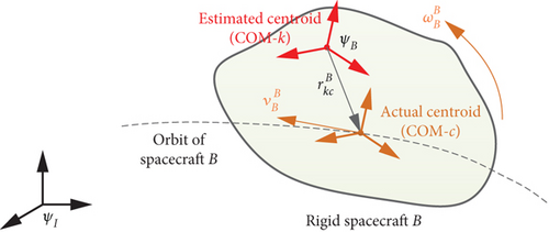
The simulation idea of this subsection is designed as follows. As shown in Figure 3, assume that the COM of the space robot B calibrated by engineering is at point k in a certain period of time, and the six-DOF motion can be described by Equation (22). However, in fact, the COM of the space robot B is at point c, at which six-DOF motion can be described by Equation (25). The position deviation between the two is . The space robot B is orbiting the earth in an elliptical orbit. The orbital parameters are shown in Table 1.
| Semimajor axis | Inclination | Argument of periapsis | Longitude of the ascending node | Mean anomaly at epoch | Eccentricity |
|---|---|---|---|---|---|
| aL = 6998455m | IL = 45∘ | ωL = 0∘ | ΩL = 0∘ | fL = 30∘ | eL = 0.02 |
Considering the gravity () and the gravity gradient moment (), the influence of other forces and noises is neglected.
Four sets of values for the position vector are taken, which are , , , and . Based on the above conditions, simulation results are shown in Figures 4, 5, 6, and 7. Figure 4 shows the orbit of space robot B under four initial conditions. Figures 5 and 6 are the orbital velocity and position under four initial conditions, respectively. Figure 7 shows the description deviation among four initial conditions; the red line represents the description deviation between and ; the green line represents the description deviation between and ; the blue line represents the description deviation between and .
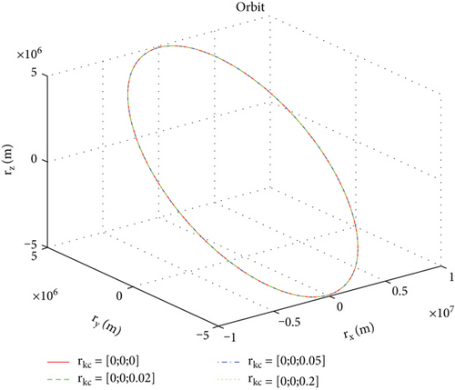
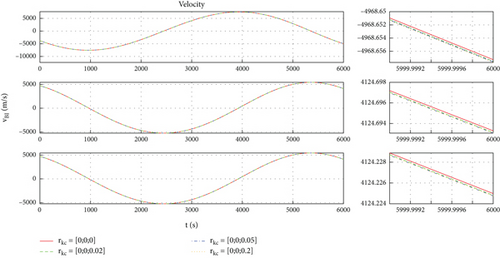
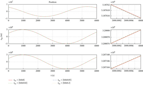
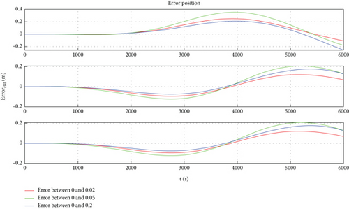
As shown in Figure 4, the orbits of the space robot B basically coincide under the four initial conditions. The simulation results are consistent with the physical phenomena, which proves the correctness of the general model. Through Figures 5, 6, and 7, one can find that there is a description deviation between the general model and centroid model, and the position description offset reaches about 0.4 m. It can be concluded that the model description error is one of the important error sources for the mission with high requirements for space robot position accuracy.
6.2. Case 2: Description Deviation of Dynamics Between Rigid Space Robot and Rigid-Flexible Space Robot
Due to the fact that the simulation in this case compares the curve trajectories of Models (30) and (54), where Model (30) is the model for the proximity collaboration task of a rigid body space robot and Model (54) is the model for the proximity collaboration task of a rigid-flexible coupling space robot, two sets of mass characteristic parameters should be set for the follower space robot. In Model (30), the mass and moment of inertia of follower space robot B are the same as in Case 1. In Model (54), the mass characteristic parameters of follower space robot B are shown (Table 2), and the fundamental frequency of the flexible body of space robot B is set as 0.174 Hz. In addition, the mass and moment of inertia of leader space robot A are the same as those of follower space robot B.
| Symbol | Value | Unit |
|---|---|---|
| 80 | kg | |
| 20 | kg | |
| JB | diag{50, 45, 50} | kg·m2 |
| Btran | [1.55 − 1.55 0.225]T | — |
| Brot | 20 − 5 1.5 | — |
| ξ | 0.005 | — |
| Λ | 1.727 | — |
Considering the effects of earth’s gravity and gravitational gradient torque, ignoring other interferences, the simulation results are shown in Figures 8, 9, 10, and 11.
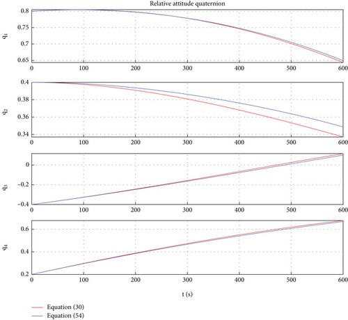
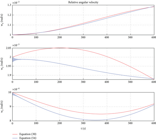
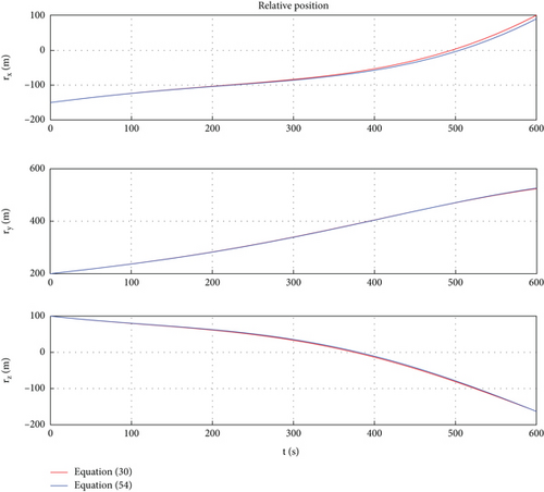

In Figures 8, 9, 10, and 11, the red lines represent the relative dynamic evolution trajectory of the space robot described by model (30), while the blue lines represent the relative dynamic evolution trajectory of the space robot described by model (54). From Figures 8, 9, 10, and 11, we can discover that the relative translational and rotational trajectory between follower space robot B and leader space robot A changes under the influence of the earth’s gravity and gravitational gradient torque. Overall, the trends of relative translational and rotational changes between space robots described by the two models tend to be similar. From Figures 8 and 9, one can find that under the action of gravitational gradient torque, the relative attitude between the rigid-flexible coupling space robots described by Model (54) generates an angular acceleration maneuver, which leads to vibration of the flexible body. Therefore, there is a deviation between the relative attitude curve described by Model (54) and Model (30). The above simulation results are consistent with the characteristics of the objects described by Models (54) and (30). In addition, from Figures 8, 9, 10, and 11, one can conclude that in the case of small space robot attitude and orbital maneuvers (caused only by gravity and gravitational gradient torque), the relative attitude and orbital errors caused by the rigid-flexible coupling effect are within a reasonable range.
6.3. Case 3: Description of Deviation of Dynamics Between Rigid Space Robot and Rigid-Flexible Space Robot Under Control
| Symbol | Value |
|---|---|
| Kp | 10 |
| 10 | |
| Kd | 500 |
| 500 | |
| c | 0.6 |
| c′ | 0.8 |
| λ1 | 0.3 |
| λ2 | 0.3 |
| λ3 | 0.3 |
| 2 | |
| 2 | |
| 2 | |
| δ1 | 0.005 |
| δ2 | 0.005 |
| δ3 | 0.005 |
| 0.002 | |
| 0.002 | |
| 0.002 |
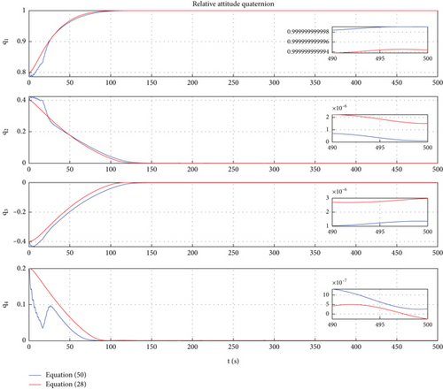
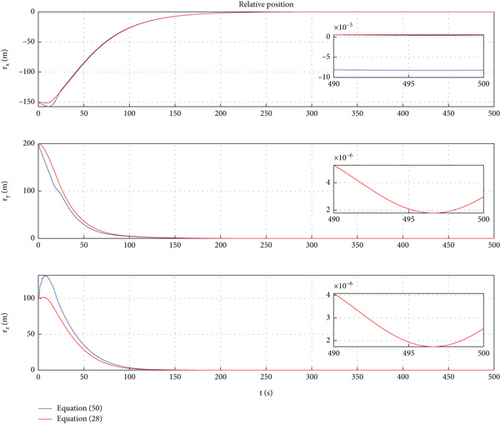
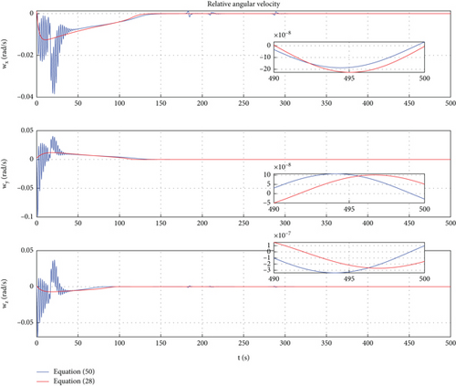
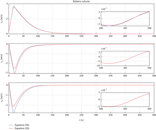
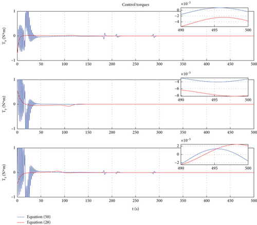
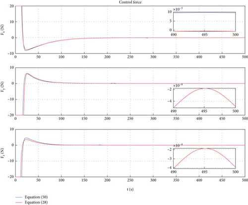
In this case, a PD control is applied to achieve motion control of Dynamic Models (30) and (54). In Ref. [9], the PD controller has been proven to have good control performance in proximity relative motion control of rigid space robots. In this paper, one can find that the PD controller also has excellent control performance for the relative motion of a rigid-flexible coupling space robot under the interference of flexible body vibration. Of course, the emergence of the excellent control effect mentioned above requires ensuring frequency band isolation between the control bandwidth and vibration. From Figures 12, 13, 14, 15, 16, and 17, we can find that two sets of control error curves deviated under the influence of flexible vibration but eventually converged to the desired value. And the changes of control force and control torque are within the achievable range of the actuator engineering.
7. Conclusions
This paper conducts innovative research on the dynamic modeling of space robots for proximity collaborative tasks. Three problems of general representation of space robot relative motion based on dual numbers are solved. At first, a six-dimensional screw representation of dual number–based dynamics is developed. With this six-dimensional screw representation, all six-DOF relative dynamic equations between rigid space robots, rigid-flexible space robots, and time-varying configuration space robots are naturally embedded into the dual screw space. Second, the general representation of the relative dynamic equation between rigid-flexible space robots is proposed. Third, the general representation of the relative dynamic model between space robots with time-varying configurations is provided. Simulation results show that compared with the classical centroid dynamic model, the general model proposed in this paper has higher precision for the scenario in which space robots have variable dynamic parameters. In addition, the general model proposed in this article has a compact representation and can be directly used for controller design. It proves the engineering application value of the general representation of the relative dynamic model. Furthermore, the model and conclusions studied in this paper can provide a fundamental theory for the dynamic modeling of multirigid-flexible coupling robots, such as space crawling robots.
Conflicts of Interest
The authors declare no conflicts of interest.
Funding
No funding was received for this manuscript.
Open Research
Data Availability Statement
Data sets generated during the current study are available from the corresponding author upon reasonable request.


