On an Autonomous Pulsar Observation–Based Timekeeping Method for Deep Space
Abstract
To provide autonomous and accurate time service for deep space missions, a pulsar observation–based timekeeping method is documented in this paper, which utilizes pulsars as the time information source. Firstly, the pulsar observation noise is remodeled as the combination of the Gaussian noise and colored noise, and the detailed expression of the colored noise is presented in the paper. An improved Grey model (GM) is proposed to describe the onboard clock evolution, which models the grey action quantity as a time-varying coefficient and attenuates the dependence of the model on the initial state. On the basis of the modified observation noise model and GM, an unscented Kalman filtering (UKF) is adopted to estimate the onboard clock error. Numerical experiments are conducted to analyze the validity of the proposed method and the impact of spacecraft positioning error and pulsar selection on the proposed method. The proposed method offers an autonomous solution for onboard timekeeping in deep space missions.
1. Introduction
For space navigation and communication, time information is one of the key parameters [1]. For near-Earth timekeeping, it mainly relies on the Earth-based time standard and Global Positioning System (GPS) [2]. GPS is not only a reliable time source but also a time transfer system, making it suitable for time synchronization and frequency distribution. Earth-based time reference also plays an important role in deep space application. The Novel Time Synchronization Techniques for Deep Space Probes (Syndee) project developed by the European Space Agency (ESA) proposed two novel clock synchronization methods for deep space probe. Both methods depend on the accurate Earth time reference [3]. For Deep Space Network (DSN) frequency and time standards, Jet Propulsion Laboratory (JPL) developed the DSN Frequency and Timing Subsystem (FTS) for NASA’s deep space activities. Its “central clock” is realized and maintained on ground [4]. However, reliance on Earth-based system can present challenges, including latency, constraints on availability, substantial construction, and maintenance cost. Thus, autonomous time reference becomes a preferable choice for deep space applications.
For autonomous time reference, highly precise and stable onboard clock is a viable option. Mercury ion clock is based on the 40.5-GHz ground-state hyperfine transition of trapped 199Hg+, providing continuous and high-stability time information [5, 6]. Using spin-polarized, ultracold atomic ytterbium, optical lattice clocks are a new type of atomic clocks benefitting from the emergence of ultrastable laser technique [7, 8]. These novel clocks show excellent stability and accuracy but have significant deficiencies. The construction of these clocks necessitates complicated instruments, strict circumstance, and high construction cost. An alternative autonomous time reference is pulsar timing. Pulsars are highly magnetized neutron stars rotating around their rotation axis with signals emitting from their poles. Continuous observation indicates that the pulsar rotation frequency shows high stability over long time interval. Consequently, pulsars are regarded as high-stability celestial clocks in deep space [9]. Compared with terrestrial clocks, pulsar timing standard indicates high autonomy, wide cover range (the solar system and even beyond), and good continuity. Researchers have studied the implementation of pulsar timing [10–12], the origins of pulsar timing error [13, 14], and the correction and compensation of pulsar time residual [15, 16]. Furthermore, several projects are carried out to verify the feasibility of pulsar timing, including the “International Pulsar Timing Array” project by Australia and Europe [17] and the X-ray Timing system and Station Explorer for X-ray Timing and Navigation Technology (SEXTANT) project by America [18, 19]. Recently, studies are conducted on pulsar-based timekeeping. A server satellite parked in a stable distant retrograde orbit (DRO) utilized X-ray Pulsar-based Navigation (XPNAV) to determine its orbital position and velocity and maintain its onboard timing autonomously [20]. The possibility of establishing time scales with high-stability performance by combining pulsars and atomic clocks was discussed in [21, 22]. The authors in [23] discussed the impact of different data spans on the accuracy of pulsar timing model parameters. The authors in [24] intended to utilize millisecond pulsar timing to enhance and maintain a space-time benchmark for future deep space application. Those research lays a solid foundation for pulsar timekeeping theory and technical application. However, there is a paucity of detailed research on the pulsar timekeeping at spacecraft for deep space missions. Timekeeping onboard a spacecraft is of great engineering value. The establishment of a local time reference at the spacecraft would increase the autonomy of the spacecraft and reduces the dependence on the Earth support. Consequently, the autonomy and exploration range of deep space missions would be enhanced.
To establish an autonomous time standard for deep space missions, a pulsar observation–based timekeeping method is documented in this paper. With pulsar timing observation, the onboard clock error can be corrected by pulsar time residual observation. However, due to various factors including the free precession motion and glitches of pulsars, the interstellar dispersion, and the spin noise intrinsic to pulsar [25, 26], pulsar time residual is influenced by timing noise, which cannot be simply modeled as Gaussian noise. This paper proposes a model that combines both Gaussian noise and colored noise to present the pulsar time observation noise. An improved Grey model (GM) is adopted for indicating the clock evolution process. With the pulsar timing observation model and the clock evolution model, unscented Kalman filtering (UKF) method is utilized to estimate the onboard clock error.
2. Basic Model
2.1. Pulsar Timing Observation Model
2.2. Pulsar Timing Observation Noise Model
2.3. Onboard Clock Evolution Model Based on Improved GM
For the evolution of atomic clocks, multiple models have been proposed in available literatures, including the polynomial model, the GM, the periodic model, and the autoregressive integrated moving average (ARIMA) model. Among these models, the GM has the advantage of being able to use small amounts of data to express the evolution process. Theoretically, a minimum of four sets of data are required for establishing a GM. With small amounts of data required, a GM can be dynamically adjusted with new data observed, which consequently increases the short-term and long-term prediction accuracy.
3. Pulsar Observation–Based Timekeeping Using UKF
As discussed in the preceding section, the clock evolution model is a nonlinear model. To facilitate the pulsar observation–based timekeeping, an UKF is adopted.
Unscented transform (UT) is the basis of UKF. The principle of UT can be described as follows.
With SVD, the loss of the positive definite of Pξ is solved and the stability of the filtering algorithm is guaranteed.
- 1.
Calculating the sigma points
- 2.
Obtaining the state transition of the sigma points
- 3.
Updating the covariance matrix and the gain
- 4.
Estimating the states
4. Simulation and Analysis
4.1. Simulation Conditions
For the simulation experiments, pulsar parameters used are listed in Table 1. The pulsar parameters are obtained from the Australia Telescope National Facility (ATNF) Pulsar Catalogue and Reference [27]. The area of the x-ray pulsar detector is set to be 10,000 cm2. The average background noise flux intensity is set to 5e−3 ph/(cm2·s) [27].
| Pulsars | Period (s) | Frequency (s−1) | Frequency drift (s−2) | Flux intensity (ph/cm2·s) | Pulse width (s) | Pulsed fraction (%) |
|---|---|---|---|---|---|---|
| B1937+21 | 1.558e−3 | 641.928 | −4.291e−16 | 4.99e−5 | 3.82e−5 | 86 |
| B1821-24 | 3.050e−3 | 327.406 | −1.735e−13 | 1.93e−4 | 5.50e−5 | 98 |
| B0531+21 | 3.339e−2 | 29.947 | −3.775e−10 | 1.54 | 3.0e−3 | 70 |
To measure the level of the timing noise, a model is presented in Section 2.2. According to reference [30], the timing noise model parameters are set as follows: C2 = exp(1.5), α1 = −1.4, β1 = 0.9, γ1 = 2.0, and T = 5. It should be noted that the timing noise model is an averaged model suitable for a large number of pulsars. Equation (13) is employed to express the timing noise intensity.
4.2. Clock Evolution Simulation
The performance of the proposed timekeeping method is analyzed in this section. For comparison, a comparative experiment with the second-order polynomial model is also carried out. All the experiment conditions are the same except the clock evolution model. For the purpose of simulation, the initial clock error is set to be 4e−5 s. The filtering interval is set to 100 s. The pulsars used in the simulation are B1937+21 and B1821-24. Besides, the position errors of the spacecraft are obtained from the augmentation method described in the preceding paper accomplished by the authors [33].
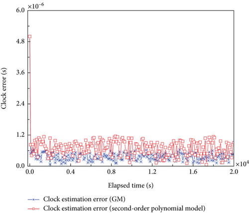
The performance of the proposed method and that of the second-order polynomial model in estimating clock error is presented in Figure 1. From the figure, it is known that with the proposed model and UKF filtering algorithm, the clock error remains at a relatively low level instead of increasing with time. Through UKF filtering, the observed pulsar time information is utilized to correct the clock evolution process. With new information from pulsar observation used, the clock error is dynamically corrected at the spacecraft. Compared with the estimation results of the second-order polynomial model, the proposed method shows better performance in clock error estimation.
4.3. Influence of the Positioning Errors
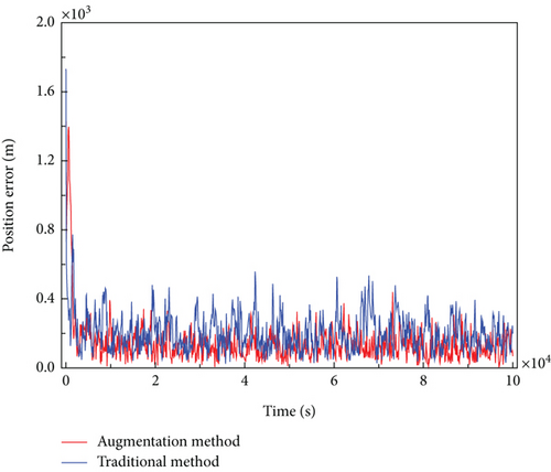
In this section, the influence of the positioning errors of the spacecraft on the pulsar-based timekeeping method is simulated and analyzed. The pulsars utilized are the same as those of Section 4.2, and the positioning errors utilized are the results obtained from the previous paper accomplished by the authors [33]. For comparison, the positioning errors from both the augmentation method and the traditional filtering method are employed in the simulation, which is indicated in Figure 2. In Figure 2, the positioning error level is evaluated by , where r is the real positioning vector and is the estimated positioning vector. The mean positioning estimation error of the augmentation method is approximately 124 m, while the traditional method is around 200 m.
As demonstrated in Figure 3, the clock estimation error of the proposed method is shown to be contingent on the magnitude of the positioning error.
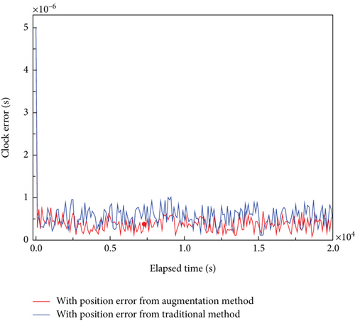
Figure 3 shows the clock estimation error of the proposed method under different positioning errors. The figure demonstrates that with a more accurate positioning estimation, the clock estimation shows better performance. With a more accurate position estimation result, the time transfer from the spacecraft to SSB would be more accurate. Consequently, an improvement in the accuracy of time transfer would result in an enhancement in the estimation of the clock.
4.4. Influence of the Pulsar Selection
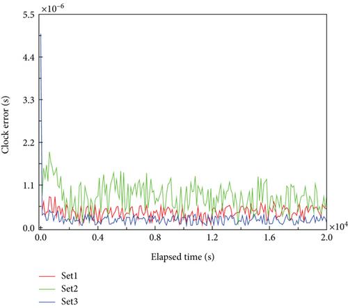
As different pulsars exhibit varying signal intensity and parameters, the selection of pulsars also influences the performance of the pulsar-based timekeeping method. For comparison, three sets of pulsar selection are chosen. In Set 1, B1937+21 and B1821-24 are observed. In Set 2, B1937+21 and B0531+21 are used. Set 3 utilizes B1821-24 and B0531+21. The parameters of the pulsars are listed in Table 1, and the other parameters employed in the simulation are identical to those outlined in Section 4.2.
As illustrated in Figure 4, the estimation performance is contingent on the selection of pulsars. Set 1 and Set 3 show similar performance. Conversely, Set 2 demonstrates the poorest estimation results compared with Set 1 and Set 3. These results underscore the significance of selecting the appropriate pulsars for clock error estimation, emphasizing the necessity for the establishment of a comprehensive and well-managed pulsar database for pulsar-based timing applications.
5. Conclusions
A pulsar observation–based method for onboard timekeeping in deep space is documented in this paper. The method realizes onboard clock error correction using pulsar observation information. The proposed method utilizes pulsar observation for the establishment of an onboard timekeeping method. Initially, the pulsar observation noise is remodeled as the combination of Gaussian noise and colored noise. The detailed model and noise level of the colored noise are presented in the paper. Furthermore, a modified GM is established to describe the onboard clock evolution, which models the grey action quantity as a time-varying coefficient and reduces the dependence of the model on the initial state. Utilizing the aforementioned modified pulsar observation noise and the GM clock evolution model, UKF is employed to estimate the onboard clock error. Numerical simulation indicates the validity of the proposed method. The simulation results also demonstrate the impact of the positioning errors of the spacecraft and the pulsar selection on the clock error estimation performance. The pulsar-based timekeeping method is distinguished by its autonomy, universality, and continuity, thus providing a novel timekeeping option for deep space missions.
Conflicts of Interest
The authors declare no conflicts of interest.
Funding
This work was supported by the National Natural Science Foundation of China (62103245 and 62273213), the Natural Science Foundation of Shandong Province (ZR2020MF095), and Taishan Scholarship Construction Engineering.
Open Research
Data Availability Statement
The data that support the findings of this study are available from the corresponding author upon reasonable request.


