Conceptualization of a Small, Uncrewed, Microwave-Powered Aircraft
Abstract
This work conceptualizes wireless power transfer (WPT) between a tracking stationary ground transmitter and a mobile aircraft. Initial ground tests are performed to determine the viability of the Friis equation, using rectennas developed for operation at 2.45 GHz at 4 dBm of optimal input power. An achieved rectifier operation efficiency of 59% is reached at this power level. A model for analyzing received power during WPT tests in flight conditions is then developed and applied for various flight paths possible with a small, electric UAV, using the designed rectenna for power conversion on the aircraft. A maximum of 429 mW is received when the aircraft is flown in a circular path centered around the ground transmitter, with a radiated power of 7 kW. Various other loiters are also analyzed, including racetrack, elliptical, and infinity-shaped loiters. The racetrack and elliptical loiters performed similarly with an approximate transmitted power of 4.5 kW and received power of 300 mW. The infinity loiter performed the worst with only 150 mW of received power with nearly 8.2 kW transmitted, which occurred primarily due to polarization mismatch between the transmitter and rectenna.
1. Introduction
Advancements in electronic sensors are enabling increasingly capable airborne platforms that are relatively small and suitable for ultralong duration missions. In general, ultralong flight durations of several days or longer require fixed-wing and uncrewed configurations. Such systems have many potential applications. When employing electric propulsion, they are relatively nonintrusive due to their relatively small physical and noise footprints, which makes these aircraft suitable for long-term data-sampling missions, an example being for ongoing surveying of wildlife habitats. A specific application in Canada is the observation of boreal caribous and their offspring over several days in order to better understand the stressors to this species [1, 2]. At this point, however, most suitable airborne observation platforms are limited in their utility by the trade-off between usable payload and onboard energy storage for powering the aircraft and its payload. Ultralong flight endurance requires an externally replenishable power supply. Smaller aircraft are especially limited by the amount of fuel that they can take along while also accommodating any meaningful payload. Taking on large amounts of fuel is only useful to a certain extent. Alternatively, aerial refueling is possible to lengthen flight times and is regularly demonstrated in various military operations. Nevertheless, the complexity of in-flight refueling makes it less suitable for many applications.
Solar power is one possible approach to provide power from an external source. Over the past years, several research teams have conceptualized [3, 4] and demonstrated the general feasibility of solar-powered flight. A relatively well-known example is the Swiss Solar Impulse 2, which was a manned aircraft that circumnavigated the world in several stages in 2015/2016 using solar and battery-stored energy. Before that, AeroVironment’s Helios was an autonomous aircraft with a wingspan of 206 ft that used solar power and energy storage. It was designed to fly at an altitude above 30 km and in excess of 24 h, while carrying nearly 45 kg in payload for remote sensing and atmospheric sampling missions [5]. Helios completed a successful flight up to 29-km altitude. Zephyr S, now part of Airbus, is another solar-powered design with a 28-m (92-ft) wingspan that completed a 65-day nonstop flight [6]. But even smaller aircraft in the 10-kg mass range have completed multiday flights [7, 8]. These past projects, as well as many more [9–11], have demonstrated the feasibility of ultralong endurance aircraft that are solar powered. Their limiting factor is, however, the need for sufficient solar irradiance, which can become quite challenging when significant cloud coverage is present and for flights at higher latitudes [12]. Moreover, any solar-powered airplane needs energy storage in order to continue flying through the night [13]. Especially at low sun angles in the morning and evening, proper flightpath planning and enhancement of the mission profile are needed to fully utilize the sun’s power [14–16].
One possibility to provide sustainable power for ultralong flight endurances is the use of wireless power transfer (WPT). WPT has been optimized in laboratory environments and demonstrated in several, limited flight tests. In 1987, a Canadian team demonstrated the general feasibility of WPT for airborne systems using an uninhabited aircraft with a 4.5-m wingspan that flew at about 150 m above ground [17]. In the 1990s, researchers from Kobe University in Japan used WPT to support sustained flight of a 2.9-m wingspan aircraft that flew about 35–45 m above a ground-based powering station [18]. In more recent work, the efficiency of WPT has been improved significantly through the use of advanced antenna array technology [19]. Fujino et al. have reported power transmission efficiencies of about 80%, while phased array antennas on the transmitter side can further improve the power transmission [20, 21]. Subsequently, it has been shown that powering an aircraft over distances of several kilometers is feasible. Especially in combination with solar power, WPT and onboard power storage with batteries have the potential to make possible ultralong flight times nearly independent of location and weather. The present paper discusses the challenges and solutions of WPT with the example of integrating such a system in an existing small solar-powered aircraft. In particular, the paper addresses questions related to the WPT link from a ground transmitter to an airborne receiver (subsequently referred to as aerial WPT) and how the latter is integrated in the existing aircraft wing structure and charging architecture. Results of several ground and flight tests are introduced to support design decisions beyond the present study.
This work intends to recreate and test WPT with aerospace applications in mind, specifically involving WPT with a tracking stationary ground transmitter and an uncrewed aerial vehicle (UAV). By performing ground tests, with a stationary transmitter and wing-mounted receivers, various tests were performed to gather enough data to extrapolate to actual flight conditions.
1.1. WPT Principles
Systems using WPT generally consist of a transmitter, which transmits energy through electromagnetic radiation, and a receiver, which is the target of the beamed power. The transmitter itself consists of an RF/microwave source with an amplifier, which generates the required signal at the desired frequency and power level, and an antenna to radiate the generated signal into free space. On the receiver side, a rectenna is required, which consists of a receiving antenna and rectifier. The receiving antenna captures the electromagnetic energy, which is then converted to usable DC energy through the rectifier. The combination of antenna and rectifier on the receiver side is dubbed as a rectenna, being a portmanteau of the two terms.
Here, Pr and Pt are the received and transmitted powers, GT and GR are the transmitting and receiving antenna gains, c is the speed of light, R is the transmission distance, and f is the frequency. The polarization mismatch is represented by the and terms with the square of their dot product representing the polarization loss factor (PLF).
While the Friis equation provides the received power at the receiving antenna, the efficiency of the rectifier, along with any impedance mismatch between antenna and rectifier, must also be accounted for to derive the total power received.
1.2. A Review of WPT Integration Into Airborne Platforms
Since its development in the early 1960s, long-range WPT using microwaves has been considered for aerospace applications. Brown, who is credited with some of the first work on microwave power transmission methods, began this trend with an integration of the technology into a microwave-powered airborne helicopter that hovered for 10 consecutive hours [23].
This demonstration led to the conception of two main applications: firstly the use of WPT to keep in-atmosphere aerial vehicles aloft indefinitely, allowing them to fulfill roles that are traditionally suited to orbital satellites, and secondly the use of WPT in orbital satellite solar arrays, to facilitate the transfer of power harvested from the sun to ground stations [24]. The motivation for these applications led to many demonstrations, some involving static transmission and reception stations; however, this review focuses on the application to mobile airborne platforms.
Part of the challenge with microwave power transfer is that a link is difficult to establish when the transmitting and receiving antennas are moving relative to each other. Additionally, an unsuitable orientation between transmit and receive antennas can substantially affect the amount of power being received. The projects discussed in the following paragraphs made notable contributions to the implementation of WPT to mobile airborne vehicles. These projects and their results are summarized in Table 1.
| Project | Year | Receiver antenna type | Total transmission efficiency | Power received | Link range | Link duration | Transmitter antenna type | Platform type | Frequency |
|---|---|---|---|---|---|---|---|---|---|
| Raytheon Helicopter [23] | 1964 | Half-wave dipoles | — | 180–280 W | 18 m | 10 h | Parabolic dish | Helicopter (3 kg) | 2450 MHz |
| SHARP [25] | 1987 | Half-wave dipoles, dual polarized | 1.50% | 150 W | 150 m | 20 min | Parabolic dish | Fixed-wing aircraft (4.5-m span) | 2450 MHz |
| MILAX [18] | 1992 | Circular microstrip | 7.0% | 88 W | 10 m | — | Circular patch phased array | Fixed-wing aircraft | 2411 MHz |
| ISY-METS [27] | 1993 | Half-wave dipoles, dual polarized | — | — | 1-20 m | 4 min | — | Suborbital vehicle | 2411 MHz |
| ETHER [28] | 1995 | Circular microstrip | 30% | 3 kW | 40 m | 4 min | Parabolic antenna | Airship (16 m) | 2450 MHz |
| Drone 1 [29] | 2019 | Circular microstrip patch | — | 42 W | 30 m | — | Circular patch phased array | Quadcopter | 5.8 GHz |
| Airship Korea [21] | 2019 | Half-wave dipole | 3%–4% | 10.2 W | 6 m | — | Horn antenna | Airship (2.2 m, 1 kg) | 10 GHz |
| Drone 2 [30] | 2022 | Microstrip (circular polarized) | — | — | 0.8 m | 7 min | Circularly polarized microstrip patch phased array | Quadcopter | 5.8 GHz |
| CREATeV conceptualization | 2024 | Microstrip patch phased array | 0.006% | 429 mW | 250 m | — | Parabolic | Fixed-wing aircraft (6.28-m span) | 2450 MHz |
The first implementation of a fixed-wing aircraft with WPT occurred in 1985, with a project called SHARP, where a 4.5-m wingspan radio-controlled airplane was powered for 20 min directly (up to an hour in later tests) using wireless power [25]. This vehicle was designed to minimize the power that is required to fly, while maximizing the available surface area for the receiving antennas to be mounted. The aircraft incorporated an electric drive train that consisted of a battery and motor to power the propeller. During the flight test, energy from the battery was used for take-off and to reach altitude, before switching the energy source to that from the rectenna array in order to maintain flight.
Improvements to the rectenna design were made to reduce the likelihood of losses due to mismatched polarization of the transmission and reception antennas and involved superimposing two layers of linear half-wave dipole antennas orthogonal to each other. These rectennas were produced on a plastic film, limiting the weight and stiffness of the array, making integration with the vehicle easier. The wireless power link harvested approximately 150 W from a transmitted power of 10 kW and had an overall efficiency of 1.5% at an altitude of 150 m [25].
Following this early success, a Japanese project called MILAX further developed the concept of a fixed-wing aircraft powered through WPT [19, 26]. Notable advancements were the inclusion of circular microstrip antennas into both the wing and fuselage, to provide a larger available area for power delivery. Delivery of power was done through a phased array transmitter on the roof of a moving car, to more accurately track the receiving antenna on the aircraft.
In conjunction with MILAX, another space-based project called METS was used to progress the possibility of solar power satellites (SPSs) [27]. A sounding rocket was launched, consisting of a phased array transmitter integrated into deployable arms in the main body of the rocket, and receiving dual-polarized rectennas were similarly integrated into the separable nose of the rocket. Once the main body and nose of the rocket were separated, WPT began from the transmitter on the rocket body to the rectennas on the nose of the rocket and lasted intermittently for up to 4 min.
The MILAX and METS projects advanced the implementation of a WPT system on an airship as part of the ETHER project, which was seen as a viable platform for high altitudes [28]. The airship was 16 m in length and used an array of 1000 circular microstrip rectenna to provide 3 kW to the two motors necessary to fly the vehicle. A parabolic antenna, emitting two orthogonal polarizations of 5-kW microwaves each, tracked the vehicle during flight.
More recently, there have been a handful of demonstrations of aerial WPT. The first of these focused on the use of a 2.2-m airship as a platform for mounting half-wave dipole rectennas tuned to higher frequencies of 7–10 GHz, in order to receive the 200 W of power transmitted via a horn antenna [21]. These tests were done within a reverberation chamber, where the reflection of the microwaves within the chamber resulted in an overall efficiency of 3%–4%. Two other demonstrations involved quadcopter-type vehicles. In 2019, a quadcopter drone flew 30 m above a phased array transmitter supplemented by 42 W of microwave power [29]. In a second study in 2022, a new transmitter array was developed that had a more uniform power density compared to previous designs and which allowed the X400 quadcopter to fly for 7 min without any battery power [30].
1.3. The CREATeV Aircraft
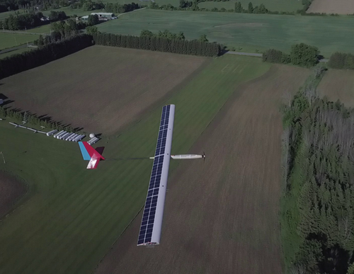
The CREATeV aircraft, shown in Figure 1, is a 13-kg solar-powered UAV developed at Toronto Metropolitan University, with the purpose to set a world record for long endurance flight [31]. To achieve this goal, the vehicle is outfitted with 96 solar cells mounted to the upper surface of a composite wing with a span of 6.28 m and a chord of 0.4 m, to charge onboard batteries during daytime flight. In order to perform this multiday flight, the aircraft must have enough power stored in its onboard batteries to sustain flight throughout the night. One way of recharging these batteries during nighttime flight, when solar power is unavailable, is to use wireless power transmission. A conceptual study using CREATeV allows the identification of challenges and solutions related to how to integrate and operate a WPT system in order to power a small UAV for near-perpetual flight.
2. WPT System
An overview of the WPT system used in this work is shown in Figure 2. The system is intended to emulate a scenario where a ground-based transmitter sends power wirelessly to an airborne UAV, in this case the CREATeV aircraft, albeit in the simplified WPT system both the transmitter and the receivers were positioned on the ground. There is a lot of infrastructure already in existence in radio and television broadcasting (lower frequencies). In the microwave regime (2.4 GHz), Wi-Fi and cellular transmissions exist.
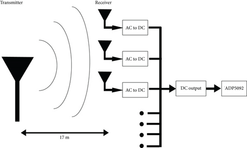
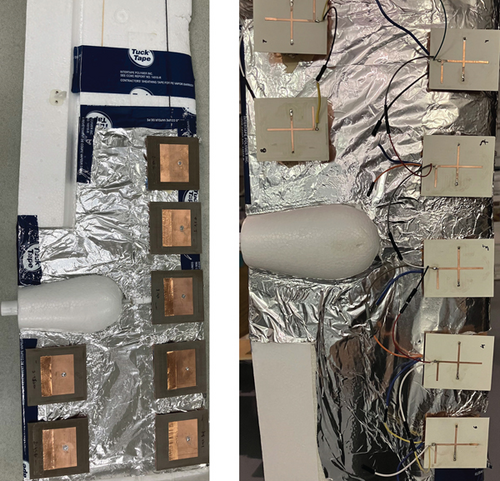
For this ground test, the transmitting antenna and the receiving rectenna array were spaced 17 m apart, with the latter integrated into the wing of the SonicModell SkyHunter RC aircraft, as shown in Figure 3. Each antenna element was paired with a rectifier for AC-to-DC conversion, with the subsequent DC output of each rectifier connected in parallel. A parallel connection was necessary to prevent damage to the connected Analog Devices ADP5092 low-power energy harvesting chip, selected for its high efficiency at low input power and its integrated maximum power point tracker (MPPT) [32]. The energy harvesting chip was connected to a 460 mAh lithium-polymer (LiPo) single-cell battery, with a nominal voltage of 3.8 V, which both acted to maintain the energy harvesting chip in a powered state while the WPT system was not enabled, and also stored the charge collected by the WPT system. A Coulomb counter positioned between the energy harvesting chip and the LiPo battery measured the current, with its output read by an Arduino Nano microcontroller board. This board also measured battery voltage, passing both measured current and voltage to a Cube Orange + autopilot by an I2C bus for real-time monitoring.
Beam forming and beam steering antenna arrays were considered on the receiver side to increase received power. This would allow for larger antenna gain values and would mitigate gain drop-off during banking maneuvers, leading to higher received power density, based on the Friis equation. However, both methods present drawbacks and additional complexities that effectively make them impractical. This is evident with beam steering, which would require phase shifters integrated with an antenna array, which would be controlled by complex computational hardware to determine the optimal interelement phase shift. These phase shifters would also draw additional power, while the antenna array would take up significant space and weight on the aircraft, both of which are limited, making phased arrays more practical for ground-based transmitters.
As such, for this project, each antenna element was directly connected to a rectifying element. This setup forgoes any advantage gained from a phased array setup, such as higher directivity or beam-shaping flexibility, for a significantly simpler receiver setup on the aircraft.
2.1. Transmitter Overview
The transmitter used in the WPT system uses a 0.6–6.5 GHz parabolic antenna from Raltron [33], connected to a VNA through a 3-W amplifier [34]. The parabolic antenna provides a gain of 20.0 dBi at 2.45 GHz with linear polarization. The VNA provided a 2.45-GHz continuous wave, which was then amplified to 350 mW and subsequently transmitted. Power limitations with the testing equipment prevented the use of higher power levels within the ground test.
2.2. Receiver Design
The receiver side consists of seven wing-mounted rectennas. Linearly polarized 2.45-GHz microstrip patch antennas were fabricated to collect the radiated RF power. These were fed through a coaxial SMA connector located on the bottom of the antenna. This allowed each patch antenna to be interfaced with a similar coaxial connector located on the underside of the rectifier. The advantage of this method is that it allowed the antenna and the rectifier to straddle the wing, that is, the antenna could be located on the underside of the wing and the rectifier on the top side, with a short section of coaxial cable joining the two through the wing, as shown in Figure 3.
2.2.1. Patch Design
A 2.45-GHz linearly polarized microstrip patch antenna was designed in Ansys HFSS [35] on a 1.524-mm thick Arlon DiClad 880 substrate [36] with a permittivity of 2.2 and a loss tangent of 0.0009. The overall dimensions of the patch were 70 × 70 mm including the ground plane, which corresponds to 2.6 times larger than the area of the patch. A coax SMA feed was placed at the bottom of the antenna to interface with the rectifier, which was fed similarly to the patch.
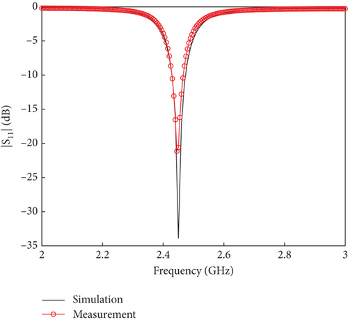
The simulated S11 is shown in Figure 4 and the simulated gain pattern is shown in Figure 5. It achieves less than −20 dB|S11| at the design frequency of 2.45 GHz with a 35 MHz–10 dB bandwidth. The maximum broadside gain is 7.67 dBi with a 3 dB beamwidth of 79°. As such, the patch antenna provides moderate gain while still allowing for power to be received over a wider range of incidence angles.

2.2.2. Rectifier Design
A single shunt-connected diode rectifier at 2.45 GHz based on the SMS7630-040LF diode from Skyworks [37] was designed in microstrip technology, simulated in Keysight ADS [38], and fabricated on a 0.762-mm thick RO4350B board [39] with a permittivity of 3.66 and loss tangent of 0.0031. The SMS7630 diode variant has been commonly used for rectifier design and features a low turn-on voltage and low junction capacitance.
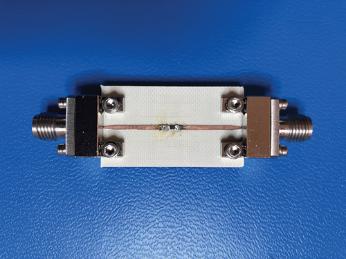
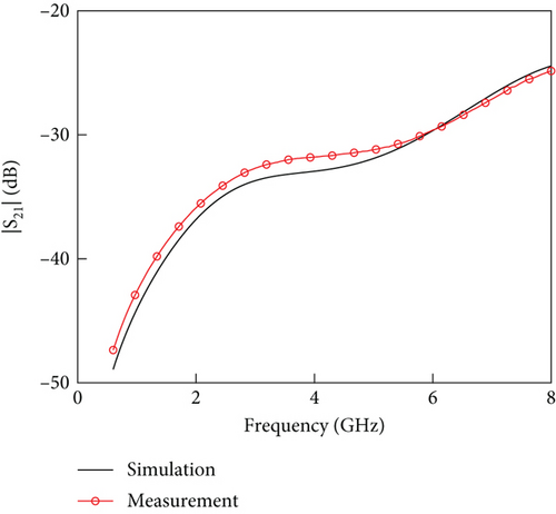
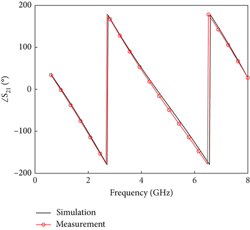
To better aid the rectifier design process, measurements of the SMS7630-040LF diode were used to create an accurate simulation model. This first step involves measuring the S-parameters of a custom-made microstrip test fixture separately from the diode, to generate a lumped-element model of the fixture in Keysight ADS. Figure 6 shows the lumped element model for the fabricated test fixture shown in Figure 7. The measured S21 parameters of the fixture without the diode are compared with the simulated S-parameters and are shown in Figure 8.

The final parameters to complete the diode model are the parasitics of the diode, which are Ld, Cd, and Rd. These parasitics along with the SDD model of the diode are shown in Figure 9.
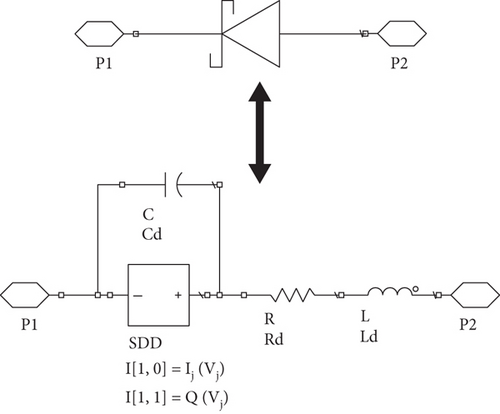
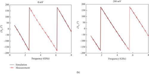
To determine the unknown constants, an optimization simulation is run in ADS to match the measured S-parameters of the fixture with the diode to the simulated S-parameters from the diode model placed in between the gap in the lumped-element model. The measurements and simulations were performed at various forward and reverse biases for the diode, to ensure the S-parameters matched over all bias levels. The parameters are listed in Table 2, while the simulated and measured S-parameters for 0 and 200 mV forward bias are compared in Figure 10.
| I0 | n | C0 | V0 | α | Ld | Cd | Rd |
|---|---|---|---|---|---|---|---|
| 37.6 μA | 1.7 | 0.13 pF | 0.52 V | 0.987 | 0.6 nH | 0.06 pF | 12.9 Ω |

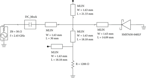
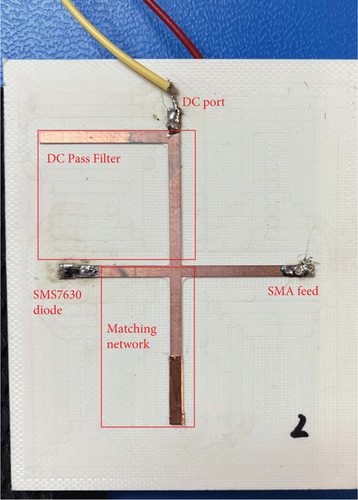
Once the diode model was determined, the matching network and DC pass filter were designed. Two quarter-wave stubs were used as a DC pass filter, and a single stub tuner was used to match the rectifier to 50 Ω at the fundamental frequency of 2.45 GHz. The second and third harmonics generated by the rectifier were small enough to not require a dedicated harmonic rejection filter and remain 20 dBm below the fundamental power.
The matching network design and optimal load and power were found through an iterative optimization method based on Zhang et al. [40]. The process involves determining an initial input power at which the diode experiences a reverse voltage close to its breakdown voltage. The diode input impedance from this can then be used to design a matching network, which in turn produces a new value for input power at which the diode experiences the required reverse voltage. This process converges to the optimal input power along with the associated diode impedance for the matching network. By repeating the above process for different load resistances and determining the efficiency, the optimal load resistance was found.
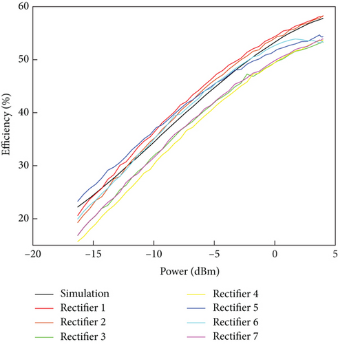
Based on the method described above, the optimal input power was determined to be 4 dBm and the optimal load resistance to be 1200 Ω. Figures 11 and 12 show the circuit schematic and closeup photograph of the fabricated board. Figure 13 shows the simulated and measured RF-DC efficiency curves for all seven rectifiers that were fabricated (Rectifiers 1–7). The measured efficiencies for the seven rectifiers were in the range of 53%–58% at the optimal input power of 4 dBm, which correlates well with the simulated efficiency of 59%.
2.2.3. Rectenna Array
The seven fabricated microstrip patch antennas and rectifiers were arranged on the wing of the SonicModell SkyHunter 1.8-m wingspan RC aircraft, as shown in Figure 3.
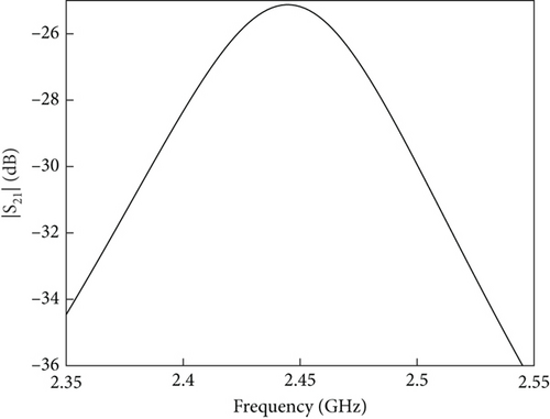
The patches were spaced sufficiently apart such that mutual coupling was negligible. This was confirmed through simulation, with a maximum simulated coupling level (∣S21∣) of −25 dB between two of the edge patches, as shown in Figure 14.
The patches were aligned such that their linear polarization vector points along the length of the wing. This was necessary, as it orients the polarization vector perpendicular to the ground (vertical polarization), thus reducing ground reflections as discussed in a report by Texas Instruments [41]. When ground to air transmission is considered, as discussed in Section 3, ground reflections are minimal, and the receiving antenna polarization can be oriented along the direction of travel of the UAV, that is, along the short edge of the wing.
The rectifiers on the top side of the wing were connected in parallel and were terminated with a single 170 Ω resistor. This was done to account for the seven 1200 Ω loads of a single rectifier placed in parallel, thus reducing the combined optimal lead resistance by a factor of seven.
2.3. Transmission Results
The wing was mounted vertically such that it could freely rotate along its lateral axis as shown in Figure 15.

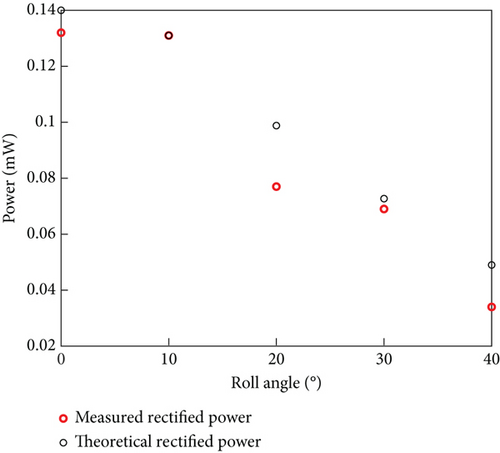
When the seven rectennas were placed onto the wing and the DC outputs were wired in parallel, the rectified power from the broadside direction was 132 μW for 350 mW of transmitted power and 17 m of range, using the transmitter setup as previously discussed. Additional data was gathered by varying the wing angle from 0° to 40° along the lateral axis of the wing as shown in Figure 15. Testing along the longitudinal axis of the wing was avoided due to objects adjacent to the transmit path.
Based on antenna gain and the measured rectifier efficiency from Figures 5 and 13 and after accounting for the varying polarization, the Friis equation can be used to calculate the theoretical received power. The theoretical and measured rectified power are compared in Figure 16 where it can be observed that they match closely. The discrepancies are likely due to reflections in the test environment and unequal rectifier performance may also affect the average rectifier efficiency used in the theoretical rectified power calculations, as discussed by Shinohara et al. [42].
As such, since the Friis equation has been shown to provide a good estimation of the received power in the ground test, it is used in the next section to calculate the received power over different loiters that a receiving aircraft can take around a stationary transmitter. In this section, an aerial WPT test between a tracking ground transmitter and the CREATeV aircraft is conceptualized, to determine the performance of the WPT link, given different flight paths or loiters that the aircraft can take around the transmitter. Prediction of the received power in the WPT link, among other parameters, is based on a modified version of the loiter analysis method [15, 43].
2.4. Outline of Power Estimation Method
Estimation of the received power at the CREATeV aircraft for the different flight paths is performed by adapting the loiter analysis method for WPT [15, 43] with the general outline of the method shown in Figure 17. The method calculates the location and attitude of the aircraft relative to a ground transmitter that is assumed to actively track and position the aircraft near the maximum of its radiation patterns. The method can be applied to different loiters, to characterize their performance in terms of the WPT link. This information is used to determine important parameters used in the Friis equation such as the receiver gain, PLF, and range, for a total of M points in the loiters, where m is the location index for the aircraft (1 ≤ m ≤ M).
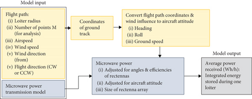
The equations presented in the following section are those that were added to the existing loiter analysis method for the calculation of the received microwave power.
2.5. Modified Loiter Analysis Method
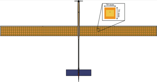
Considering the usable surface area on the lower surface of the CREATeV wing and the area of the patch antennas outlined in Section 2, a total of 312 rectennas can be placed on the bottom of the wing, as shown in Figure 18, which corresponds to a total receiving area, Arect,Air, of 1.53 m2. As this paper discusses a conceptual modification to the CREATeV aircraft, there has been no redesign of the wing for rectenna integration. For the real-world application, it is anticipated that the rectennas will be fully integrated into the wing skin, which should only increase the weight of the wing. There should be no change to the aerodynamic properties of the aircraft with the addition of rectennas. The current solar array manufacturing involves its infusion with fiberglass to manufacture the top layer of the wing skin. This manufacturing method results in a low profile of the solar array that allows for maintaining the airfoil shape. A similar process should be used for integration of the rectenna array on the lower surface of the wing.
For the purpose of this work, all rectifiers on the aircraft are assumed to be the same, and their rectification efficiency is set to be the average of the efficiency values in Figure 13 at the relevant power levels.
Figure 19 shows the relevant transmit and receive vectors, along with the polarization orientation for the transmitter and receiver.
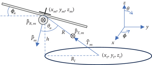
The PLF reaches a maximum of one only when the aircraft moves in the direction, relative to a transmitter centered at the origin of a polar coordinate system.
A potential tracking system that can be used with the ground transmitter is the SatNOGS rotator tracker [44], equipped with an autopilot and used in accordance with ArduTracker [45]. Simple pan and tilt servo mechanisms can also be used with ArduTracker but are not able to carry the load of the transmitting antenna and any required transmitting equipment as well. The use of a ground tracker and aircraft combination requires that both components be equipped with an onboard controller, GPS, and transmitting/receiving antenna so that communication can be performed.
2.6. Loiter Ground Track
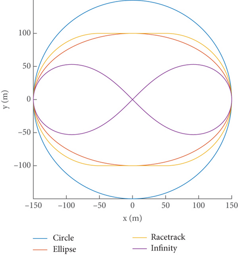
Four loiter path shapes were evaluated, including circular, elliptical, racetrack, and infinity shapes. The ground transmitter is placed according to the origin of these loiters, with coordinates (0, 0, 0). This is done to optimize the received power throughout the entirety of the flight path, thus maximizing the average power. For each path, coordinates are placed in the xy-plane indicating the position of the aircraft in the loiter. The coordinates are placed using (14)–(20), for M number of points in each loiter.
Here, t is an array of linearly spaced points from zero to 2π.
All equations discussed in this section result in coordinates whose sequence results in clockwise flying loiters. For loiters flown in the counterclockwise direction, the order of the x- and y-coordinates array is reversed.
All four paths are shown in Figure 20 and a constant altitude is assumed. The loiter radius, Rl, for the circular path is set to 150 m, while the rest are set to 100 m.
2.7. Extending Ground Test Results to Flight Conditions
Based on parameters shown in Table 3 and the paths defined in Figure 20, an aerial WPT scenario involving the CREATeV aircraft is analyzed, given the considerations outlined below. Firstly, as stated above, all rectifiers on the aircraft are considered to have the same efficiency, which is set equal to the average measured efficiency of the seven rectifiers used in the ground test at a given input power level. Secondly, the receive antenna polarization is set to be along the flight path of the UAV, with horizontal polarization on the ground transmitter. This aligns the receive and transmit polarization vectors for the circular flight path resulting in no polarization mismatch (PLF = 1). Lastly, the transmit power is set to a constant value for each loiter, to simplify the transmitter design. This is done such that the maximum received power Pr within all points in the loiter is at 2.5 mW or less, while also ensuring that the transmit power is set at its lowest possible value to meet this condition. The value of 2.5 mW corresponds to the optimal input power for the rectifier at which it operates with the highest efficiency. Exceeding this value was found to damage the rectifiers, permanently reducing their operational efficiency; therefore, the transmit power was limited such that the received power never exceeded 2.5 mW.
| Input parameter | Value |
|---|---|
| Altitude | 250 m |
| Frequency | 2.45 GHz |
| Transmitting antenna gain | 20.0 dBi |
| Number of rectennas | 312 |
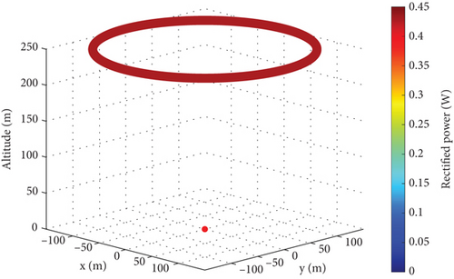
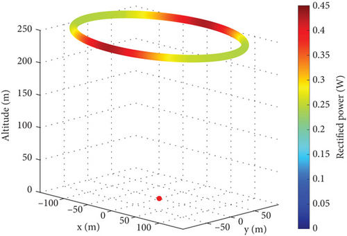
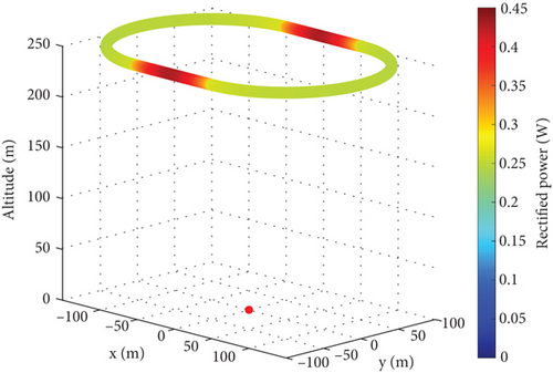
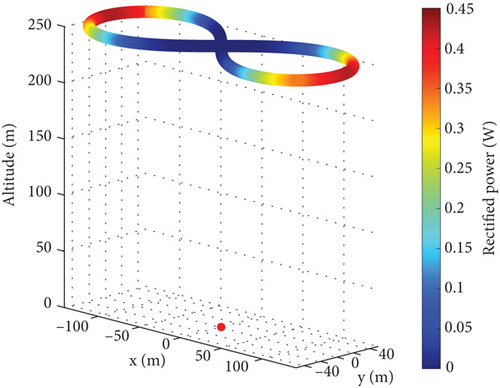
The power received by the array at various points around the loiters is calculated using (6) and shown in Figure 21. In the figure, the transmitting ground antenna is placed directly under the loiter path at the coordinates (0, 0, 0) and is indicated by the red dot. The color of the plot indicates the received microwave power, where red indicates a greater power received, with the color scale shown on the right-hand side. The loiter is flown at zm = h = 250 m altitude above ground, indicated by the z-axis.
| Loiter shape | Power transmitted (W) | Average power received (312 rectennas) (mW) | Total receiver efficiency (%) |
|---|---|---|---|
| Circle | 7066.0 | 429.1 | 42.4 |
| Ellipse | 4668.2 | 305.1 | 42.2 |
| Racetrack | 4380.3 | 294.8 | 43.4 |
| Infinity | 8183.2 | 148.1 | 10.4 |
The total receiver efficiency provides a better indication on the performance of the receiving rectennas on the aircraft compared to the total efficiency (Pavg,Air/Pt), as the latter is influenced by a significant loss in free space given by L = 10log((4πRf2)/c2) which is around an average of 88 dB for the loiters. This loss is unavoidable and stems from the inverse squared decay of power with distance.
It can be observed that apart from the circular flight path, the received power can vary significantly at different points in the loiter. While this is partly due to the changing distance between the transmitter and aircraft and the fixed transmit power for a loiter, the bank angle and the polarization can also significantly affect the received power. For instance, in the infinity path, both polarization and bank angles strongly influence the received power. Near the end of the lobes of the infinity loiter, the PLF is close to one but decreases to zero as the aircraft starts moving directly toward the transmitter, resulting in almost no received power at the center of the infinity pattern. This is despite the aircraft being closest to the transmitter compared to the other three loiters. The bank angle however is greater near the end of the lobes, requiring a higher transmitter power to achieve the maximum power of 2.5 mW at the rectifier. The loss in the infinity path is reflected in the average power received and the transmitted power, which are 148.1 mW and 8.18 kW, yielding a net receiver efficiency of only 10%.
This is unlike the circular flight path, which also has a high transmit power of 7066 W but receives a constant 2.5 mW at all points, resulting in efficiencies closer to the elliptical and racetrack loiters. For the latter two similar performing loiters, a lower transmit power of approximately 4.5 kW is required, albeit with lower received power of 300 mW, so a trade-off exists between the transmit power and the average received power for the circular, elliptical, and racetrack flight paths. To further characterize the loiters, especially the elliptical and racetrack loiters, requires gauging their aerodynamic impact on the aircraft, which is not considered in this work.
Lastly, the polarization is an important factor to take into account, when determining the optimum flight path as evident from the infinity loiter. While a CP receiving antenna could potentially help with the PLF in the infinity loiter, it is important to note that a wide angular axial ratio would be required due to the oblique transmission angles between transmitter and receiver, thus increasing design complexity on the receiving antenna. Furthermore, transmitter complexity is also increased, requiring a CP transmitting antenna. As such, the circular, elliptical, and racetrack loiters around the stationary transmitter were considered superior to the infinity loiter, when performing WPT with a fixed-wing aircraft, due to a significantly simpler setup and optimum performance. Generally, a CP antenna would be preferable when considering WPT to a drone which can be hovered over the transmitter or with an aircraft with a larger area, to allow for better placement of the CP antennas.
Aerial WPT performance can be improved through the use of a higher gain transmitter, which would help reduce the transmit power. The overall rectified power can also be increased by using rectifiers with higher power handling capabilities and improved efficiencies. This results in higher incident powers on the wing, with each rectifier element being able to convert a greater amount of the received energy to usable DC energy without increasing the rectenna count. Further investigation into alternative receiver rectenna polarizations, dual-polarized transmitters and receivers, multiple transmitter setups, or a variable power transmitter setup could also potentially increase the received power. This would be followed by integration of the rectennas with the CREATeV aircraft, along with detailed analysis of the aerodynamic impact of the placement of the rectennas on the aircraft.
3. Conclusion
A method to theoretically calculate WPT performance between a ground-based transmitter and a mobile aircraft has been presented. This setup is considered for providing supplemental power to UAVs, with the CREATeV aircraft being the model used for this purpose. The rectenna used in this conceptual model was designed and tested at 2.45 GHz, with the rectifier achieving a maximum efficiency of 59.0% at 4 dBm of input power.
Using the modified loiter analysis method, four flight paths were analyzed which included a circular, elliptical, racetrack, and infinity shapes. Based on these results, a maximum of 429 mW was received when the aircraft was flown in a circular path centered around the ground transmitter, with a radiated power of 7 kW. The infinity path performs the worst compared to the other three loiters, with a high transmit power of nearly 8 kW and a low receiver efficiency of 10%. It can be concluded that WPT between a tracking stationary ground transmitter and an aircraft is feasible, although with very limited efficiency.
Conflicts of Interest
The authors declare no conflicts of interest.
Funding
This work was supported by Columbiad Launch Services through the Mitacs Accelerate program, project no. IT26759.
Open Research
Data Availability Statement
The data that support the findings of this study are available from the corresponding author upon reasonable request.


