Multiperspective Structural Integrity Investigations on the Rotor Blade of Axial Flow Compressor Under Various Rotodynamic Loading Conditions Using Enhanced Computational Analyses
Abstract
Small gas turbine (SGT) engines power the latest generation of unmanned aerial vehicles (UAVs). This study investigates the axial flow–natured rotor blades of an SGT compressor. Rotor structures in axial flow compressors have failed due to complex stress scenarios. Lightweight, high-resistance material can reduce the failure rate of axial flow compressors in fixed-wing UAVs. Compressor blade designs are completed in 3DEXPERIENCE after extensive material investigation, in which the design data are evaluated through standard analytical procedures. First, an axial flow compressor blade for a long-range UAV is analyzed using computational fluid dynamics, in which imposed the complicated rotodynamic conditions in a single moving reference frame to the axial flow compressor rotor blade. Curvature and proximity discretization are employed in conjunction with ANSYS Mesh in this study. The edges and faces are scaled by a local mesh facility. Because of the intricate nature of the flow, an enhanced wall treatment turbulence model based on the k-epsilon parameter was employed. The computational method based on fluid-structure interaction (FSI) uses aerodynamic pressure distributions on the compressor blade as a basis for structural analyses. For this structural investigation, FSI has been used with a single-coupling direction. Composite compressor blades are put through an FSI inspection to ensure they are perfect. Epoxy has been used to analyze the structural integrity of a variety of modern composites, including those made from carbon fiber–reinforced polymers, glass fiber–reinforced polymers, and Kevlar fiber–reinforced polymers. Researchers used ANSYS Workbench to conduct in-depth analyses of over 25 lightweight materials. The blades are free to move in reaction to a shift in position at low, medium, and high rotational speeds, while the main hub remains stationary. This study lays the door for the development of axial flow compressors using nontraditional lightweight high-resistance materials.
1. Introduction
Unmanned aerial vehicles (UAVs) have witnessed increased utilization across several industries, encompassing agriculture, disaster management, military operations, and search and rescue endeavors, throughout the recent decades. To operate effectively, UAVs necessitate the presence of a fully operational propulsion system. In recent years, UAVs have been driven by a variety of power sources, including internal combustion engines and electric motors. Currently, there is a need for a more reliable and secure propulsion system for UAVs operating at mid and high altitudes, in both military and commercial contexts. Numerous investigations are underway to address this requirement, focusing on the propulsion systems of UAVs. The small gas turbine (SGT) is well suited for high-endurance and medium-range UAVs due to its compact dimensions and superior operational capabilities. In recent years, notable advancements in performance and efficiency have been observed in existing gas turbine engines, although similar enhancements have not been shown in SGTs. The utilization of SGT engines has emerged as a prevalent technological advancement in the field of UAVs.
The primary focus of this examination of the SGT compressor was directed towards the axial flow compressor blades. Axial compressors exhibit higher efficiency levels when operating at low input mass flow rates, enabling more effective handling of lower flow rates. Consequently, these compressors have gained popularity in smaller engines. The system comprises of both fixed and rotating blades, along with a stator and rotor. The fluid undergoes acceleration due to the rotational motion of the blades, while the stationary blade stores the fluid’s kinetic energy as other form of energy as pressure energy. The compressor blades experience an inertial force, resulting in stress and a decline in the compressor’s operational efficiency. The structural integrity of the blades may be compromised due to inertial pressures and stresses, hence impacting the fluid flow. Fluid structure interaction (FSI) can be employed for the purpose of identifying the stresses that are created. The analysis of FSI is employed to forecast the behavior of structures subjected to fluid flow. The transmission of analytical data can be categorized as one-way and two-way coupling, depending on the nature of the interaction. In here, one-way coupling is used as the go-through method for the analysis of the rotor blades. This method was adapted due to its adaptability of importing aerodynamic pressure loads from the computational fluid dynamics (CFD) analysis into the structural analysis of the blades. As the data transfer is unidirectional, the computational time taken for the system to solve for the outcomes is comparatively lower than that of two-way coupling, and also, a constant grid can be maintained for the entirety of the analysis without needing to be changed like in the two-way FSI analysis. A considerable drawback is that airflow will not be affected with respect to the deformation of the rotor blades. As the flow of air does not change with respect to the deformation of the blades when the pressure load is acting on them and as the blade is not made of elastic material, one-way coupling was opted over the two-way coupling FSI analysis. Composite materials are significant in the aerospace sector due to their superior specific strength, reduced weight, favorable stiffness-to-density ratio, and various physical properties. These materials are currently playing a crucial role and are expected to continue doing so in the future. The utilization of composite materials in the fabrication of compressor blades has a dual advantage of reducing production expenses and enhancing mechanical characteristics. A diverse range of composite materials can now be utilized for the construction of axial compressor blades. UAV gas turbine blades are manufactured with state-of-the-art technology. Compressor blades are conventionally fabricated using a diverse range of materials, such as sintered powder alloys, aluminium alloys, and titanium aluminide–based alloys.
The propulsive performance of the microgas turbine has been enhanced by the endeavors of Large and Pesyridis [1]. The aim of the authors’ project is to employ a variable gearbox system to convert a microjet engine into a microturbofan engine. The initial configuration of a matched low-pressure compressor (LPC) was performed using mean calculation methodologies. The research performed has resulted in improvements in the operational efficiency of microgas turbine engines [1]. In the authors’ study, Eliseev and Piskunov [2] employed a vibrational computation approach to effectively determine the dimensions of blades in composites with partial concentration. The authors demonstrated that this method, which incorporates effective moduli and Lagrange equations, is both straightforward and efficient [2]. Ujjawal Ajaiswal employed the mean line approach in their study to examine the properties of axial flow compressor blades. The construction and simulation of the axial flow compressor were undertaken to examine the variations in mass-to-pressure ratios at different altitudes. In the field of fluid dynamics prediction, both theoretical and analytical findings exhibit a high degree of agreement within acceptable parameters. The user presented a numerical citation [3]. Pavlenko et al. have put out a proposition on the application of composite materials and advanced alloys in various phases of compressor systems, with particular emphasis on the aerodynamic surface of compressor blades. The recommendation provided is grounded in a comprehensive examination of the thermal and structural components. The recommended materials encompass sintered titanium, an innovative iteration of aluminium, and an alloy comprised of titanium aluminides. The principal rationale behind this advice is to optimize the production process [4]. Tsai et al. conducted an analysis on an engine that is fitted with a tiny turbojet propulsion system. The user’s content does not contain any information to alter. The design process initiates with a thorough parametric exploration and involves theoretical design, preliminary design, detailed design, two-dimensional CFD analysis, investment casting, and engine testing [5]. Srinivas et al. developed an axial flow compressor using Pro/Engineer software, wherein modifications were made to the blade count. Compressor models undergo structural study to assess their mechanical durability. Based on the outcomes of the study conducted by researchers [6], it is suggested that the fabrication of compressor blades should utilize titanium alloy. The examination of this specific phase of the centrifugal compressor was carried out by Vijayanandh et al. [7]. The comprehension of the material composition employed in the compressor of a UAV holds significant significance, even in scenarios where the type of compressor may differ. The consideration of the mechanical properties of the materials in this work was crucial for the purpose of conducting computer simulations [7]. To provide a comparative examination with commonly utilized commercial alloys, the researchers opted to employ a varied selection of polymer matrix composites for the blades of the compressor of the UAV. The examination of gas turbine engines and their subcomponents, for example, turbines and nozzles [8–10], has provided significant knowledge regarding the primary emphasis of axial flow compressors. The most effective strategy for resolving the issue is to utilize FSI computation. The works cited in references [8–10] have been widely recognized as excellent instances of computational operations that display elevated degrees of intelligence. The cited works within this research [8–10] examine various facets of rotodynamics, aerofoils, and pumps by employing CFD methodologies. The present study employed a CFD simulation to evaluate the aerodynamic pressure experienced by the compressor blade. This pressure assessment is crucial in selecting the suitable material for the blade. In summary, to gather necessary data for the investigations, to determine appropriate boundary conditions for the CFD and finite element analysis (FEA) approaches, and to obtain the properties of the different lightweight materials, a range of studies utilizing FEA has been undertaken [8–10].
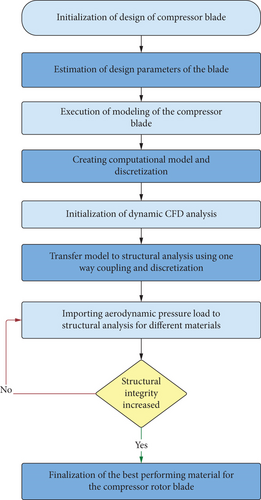
From the understandings, the proposed work focuses on the axial flow rotor blades of the SGT compressor using composite materials. This research focuses on the investigation of compressor blades which operate based on the axial flow of air through the compressor, within the SGT engine designed for UAVs. Due to the intricate loading conditions experienced by the rotors of axial flow compressors, instances of structural failures have been observed. To mitigate the occurrence of failure, it is imperative to integrate a lightweight material with high resistivity into the axial flow compressor of fixed-wing UAVs. 3DEXPERIENCE is employed for the finalization of the conceptual design of compressor blades, which is predicated on a comprehensive review of the existing literature pertaining to blade design. The blade of an axial flow compressor, specifically designed for high altitude and long-duration UAVs, is initially subjected to the CFD analysis [11, 12]. The rotor blades of the axial flow compressor are subjected to rotodynamic conditions using the single-moving-reference-frame technique. In this study, the ANSYS Mesh tool is utilized to implement the discretization procedure, which involves the imposition of curvature and proximity considerations. Furthermore, the determination of edge size and face sizing is facilitated by the local mesh facility. The computation incorporates the increased wall treatment based on the k-epsilon turbulence model, due to the presence of a complicated flow. The boundary conditions include the pressure intake as the input, the pressure outlet as the output, and the consideration of no slip for frictional information. In this study, the term “low altitude” refers to the working environment, and so, the operating pressure is assumed to be 101,325 Pa. The coupled algorithm for the pressure correction process is implemented because of the imposition of a pressure-based solver. The aerodynamic pressure distributions and velocity variations on and over the compressor blade have been documented and hence utilized as an input for a computational technique that relies on FSI. The structural investigation utilizes the one-way coupling–based FSI technique. The utilization of a nondestructive testing method known as the FSI approach is employed for the purpose of assessing the structural soundness of compressor blades that are fabricated from a range of composite materials. Structural investigations have been conducted on epoxy-based carbon fiber–reinforced polymers (CFRPs), epoxy-based glass fiber–reinforced polymers (GFRPs), and epoxy-based Kevlar fiber–reinforced polymers (KFRPs). A comprehensive analysis of over 25 lightweight materials has been conducted using ANSYS Workbench. The primary hub remains stationary, while the other blades are allowed to respond to remote displacement conditions. The findings of this study have established a strong basis for the ongoing advancement of axial flow compressors through the utilization of alternative materials [13, 14]. The complete processes involved in this imposed work are systematically revealed in Figure 1.
2. Methodology—FSI
An improved methodology is necessary to address the operational conditions imposed by the compressor blade of the proposed UAV. To identify the optimal composite material for the axial flow compressor, the present investigation, titled “Fluid Structure Interaction,” undertakes a comprehensive analysis and comparison of the compressor’s performance when utilizing different composite materials.
2.1. Conceptual Design
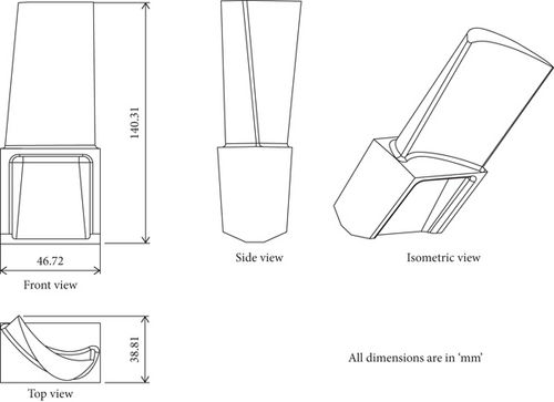
The necessary design data of the compressor rotor blade was derived by the utilization of the hub-to-tip ratio, design factor, and velocity triangle. Now is the opportune moment to choose the appropriate airfoil from the NACA airfoil database. The NACA 65 series is widely utilized in contemporary compressor design. The selection of an appropriate airfoil is contingent upon the desired camber. Based on our calculations, it has been determined that the NACA 65410 [3] airfoil is very suitable for meeting our specific requirements. The model of the compressor blade was solely derived from a comprehensive analysis of existing literature [1, 8], as the primary focus of this endeavor lies in material optimization. The measurements conducted encompassed length of chords at different locations, span length of the blade, hub diameters, and pitch angle of the blade. The detailed compressor blade model was created using 3DEXPERIENCE software. 3DEXPERIENCE is a versatile computer-aided design program that offers a range of surface and module solutions across multiple platforms, catering to various applications. The ICEM surfacing technologies may be utilized to create intricate and innovative designs in several fields, such as industrial design and Class-A surfacing. These designs can then be modified and verified using the visualization capabilities offered by this solution. 3DEXPERIENCE can be utilized at several stages of the product design continuum, encompassing both the inception of a design and the utilization of pre-existing 2D designs [15, 16]. The design parameters of the compressor blade, along with the conventional viewpoints of a singular compressor blade, are examined, as depicted in Figure 2.
2.2. Discretization
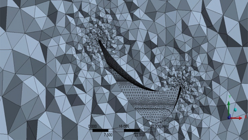
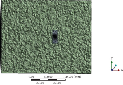
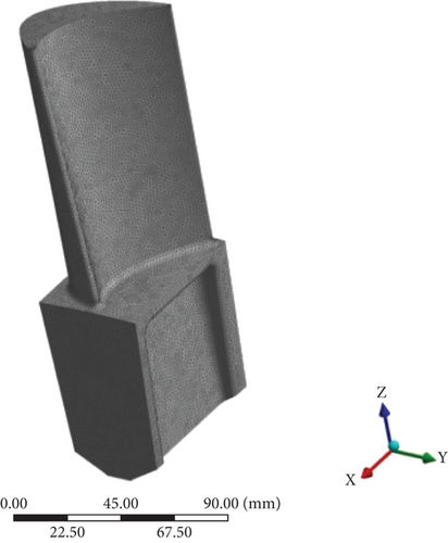
The computer solver that has been selected utilizes a solution approach known as the finite volume method (FVM). The ANSYS mesh tool was utilized to generate the internal elements to simplify the computational model. The control volume was formed by utilizing a compressor blade with a radius of 500 mm, which adopts a cylindrical shape. The blade span is multiplied by three-tenths for both the front and back portions as the boundaries of the control volume. The control volume is provided with a blade span that is five times its size at both the top and bottom. Tetrahedral-based unstructured grids are commonly employed in CFD and FEA simulations due to their ability to accurately represent complex geometries. In the context of FEA computations, a solid mesh is created within the mechanical model, while a fluid model incorporating control volume is formed using the fluid tool. The mesh is constructed through the utilization of a proximity-based approach in conjunction with a curvature size function. Unstructured construction entails a potential compromise in the quality of the mesh, necessitating a heightened level of caution and resulting in the production of pieces with a 90% quality rating. Figures 3, 4 and 5 depict prevalent mesh models generated [17, 18].
2.3. Boundary and Initial Conditions
The utilization of the pressure-based solver in Fluent Setup is necessary for this research due to its reliance on incompressible flow conditions. Furthermore, this study also introduces a density equation that is derived from the principles of incompressible flow within an axial flow compressor. For the inlet of the computational model, it involves the utilization of a velocity inlet with a magnitude of 80 m/s, and a pressure of 202,650 Pa is exerted on the output as the boundary conditions. The applied pressure is measured at 116,523.75 Pa, and the blade is assumed to possess wall-like characteristics, with no occurrence of slippage during the process. In this challenging investigation, it is imperative to employ the coupled pressure–velocity coupling technique and hybrid initialization. This necessitates conducting 10,000 iterations of the analysis [19, 20].
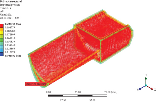
The fixed support utilized in FEA is positioned at the lower section of the blade. When choosing a material, it is common practice to examine physical parameters like Young’s modulus, Poisson’s ratio, density, coefficient of expansion, and other relevant factors. This experiment utilized four distinct variations of CFRP, five distinct variations of GFRP, and KFRP. Material qualities were identified through the utilization of findings derived from a comprehensive range of literature investigations [19, 20]. In addition to the fundamental structural boundary conditions, the utilization of one-way coupling is employed to transfer the pressure load from the aerodynamic CFD simulations on the compressor blade’s surfaces. Figure 6 illustrates the initial condition of the imported pressure from the CFD analysis.
2.4. Governing Equations and Their Explanations
2.5. Grid Convergence Test
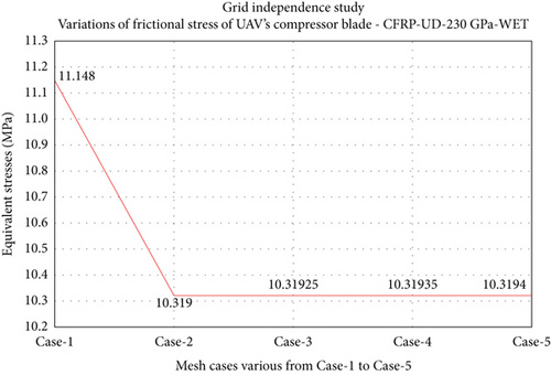
The inclusion of a grid convergence test is an essential component of computational-based research due to the high reliability of its results, making it impractical to omit. The establishment of proper mesh and boundary conditions is a direct consequence of conducting this test. The present work used CFRP-UD-Wet material to examine the FSI outcome. The generation of tension in the compressor blade is a critical aspect in all situations. After evaluating five various mesh cases ranging from 10 to 24 lakhs, it has been determined that Case-2 mesh exhibits the highest level of performance. Figure 7 illustrates the graphical representation of the results obtained from the grid independence study [8].
2.6. Validation Study on CFD
Through experimental correlation studies, validation has been carried out on this work. The experimental outcomes and boundary conditions are extracted from literature survey [1, 8]. With the necessary boundary conditions, the aerodynamic flow analysis was performed, and some of its results are revealed in Figures 8, 9, and 10.
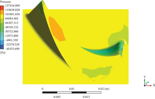
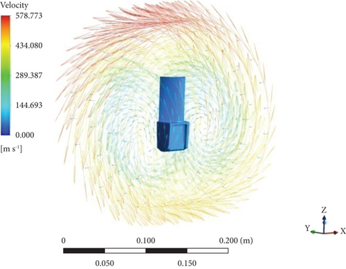
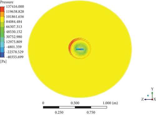
The obtained aerodynamic pressure and velocities from the imposed computational outcomes are compared with experimental outcomes [1]. The outcomes were exactly matched with each other, so the authors decided to apply the current computational approach to all other shortlisted working environmental conditions such as 10 m/s with 10,000 RPM; 20 m/s with 80,000 RPM; 40 m/s with 150,000 RPM; and 60 m/s with 180,000 RPM.
3. Results and Discussions
The research began with determining the design parameters of the compressor blade. With that, the blade was designed using 3DEXPERIENCE. The designed model was then incorporated into ANSYS fluent to perform the CFD analysis to obtain the aerodynamic behavior of the compressor blades. Then, proceeding with the FSI analysis, the aerodynamic pressure obtained from the CFD analysis was imposed as an initial condition, and appropriate boundary conditions were imposed to obtain proper results. The results obtained were recorded and discussed in this section. The structural integrity of the materials is ranked based on the physical response of the blade when subjected to the aerodynamic load imported from the CFD analysis. Some of the parameters on which the materials will be ranked are total deformation, equivalent stress, and equivalent elastic strain. The best material which can withstand the imposed boundary conditions for the operating environment of the compressor blade will have lower overall deformation, preventing the blade from undergoing high amount of stress from the aerodynamic pressure load [23, 24].
3.1. CFD Results
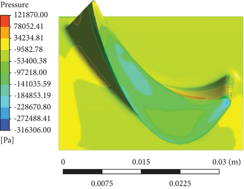
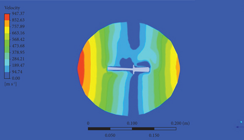
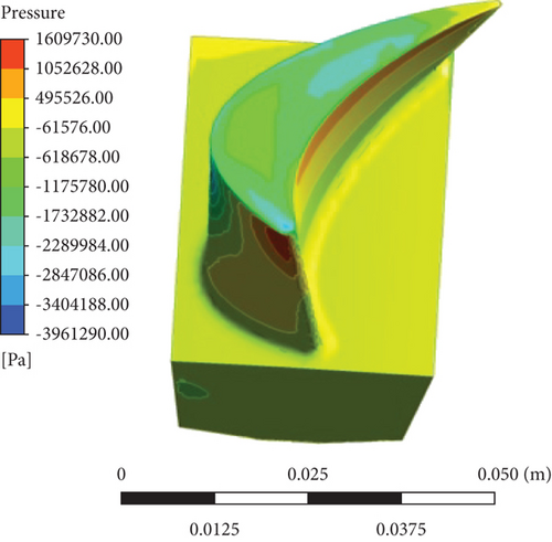
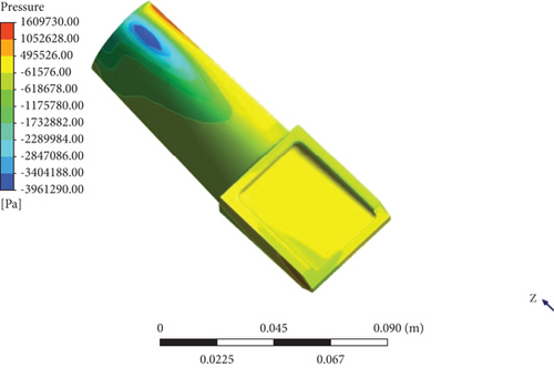
CFD analysis was performed with the computational model with proper boundary conditions for various cases such as different inlet velocities and RPMs such as 10 m/s with 50,000 RPM and 20 m/s with 80,000 RPM for the compressor blades, and the acquired results such as pressure and velocity across the blade during various boundary conditions are shown in Figures 11, 12, 13, and 14, respectively.
3.1.1. Aerodynamic—10 m/s With 50,000 RPM
Figures 11 and 12 illustrate the pressure distributions and velocity variations on and over the compressor blade at 10 m/s inlet velocity with 50,000 RPM of the rotor blades during the CFD analysis.
3.1.2. Aerodynamic—60 m/s With 180,000 RPM
Figures 13 and 14 illustrate the pressure distributions and velocity variations on and over the compressor blade at 60 m/s inlet velocity with 180,000 RPM of the rotor blades during the CFD analysis.
3.2. FSI Results
With the aerodynamic pressure load acquired from the CFD analysis, it was imposed on the compressor blades to perform the FSI analysis to determine the appropriate material requirements for the blades. The FSI analysis was conducted for each example of the CFD study, considering different boundary conditions. The obtained results were documented and analyzed in this paper.
3.2.1. BC—10 m/s With 50,000 RPM
For the respective boundary conditions, the FSI analysis was performed, and results were recorded. Figures 15, 16, 17, 18, 19, 20, 21, 22, 23, 24, 25, 26, 27, 28, 29, 30, 31, 32, 33, and 34 depict the results of factors such as total deformation, normal stress, equivalent stress, stress intensity, and strain energy on the respective materials for a boundary condition of inlet velocity of 10 m/s with 50,000 RPM. Figures 15 and 16 are some of the samples from the FSI analysis, and Figures 17, 18, 19, 20, 21, 22, 23, 24, 25, 26, 27, 28, 29, 30, 31, 32, 33, and 34 give the graphical representation of the results obtained during the comprehensive analysis.
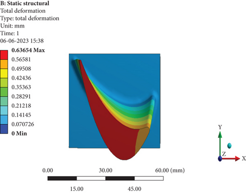
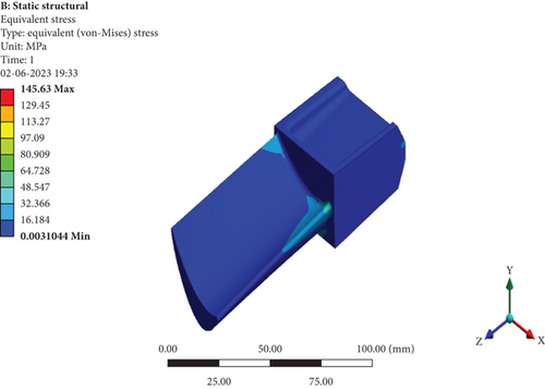
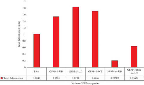
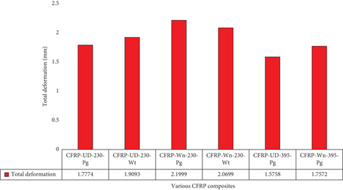
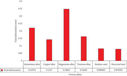
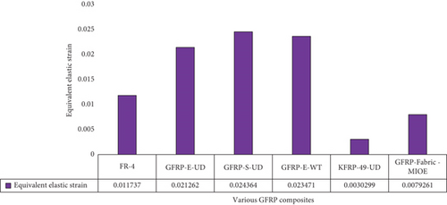
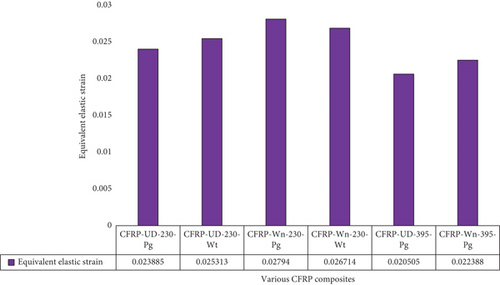
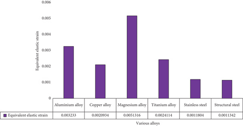
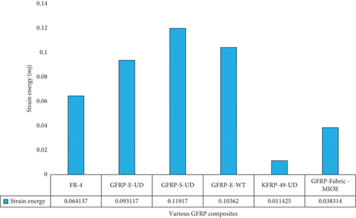

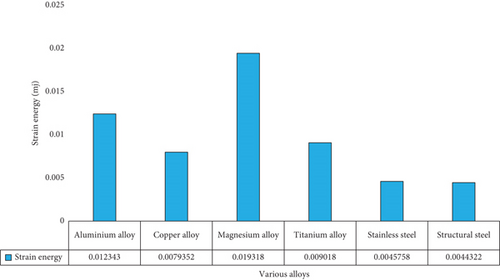
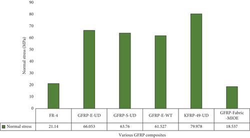
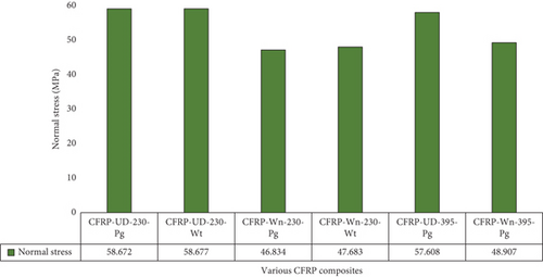
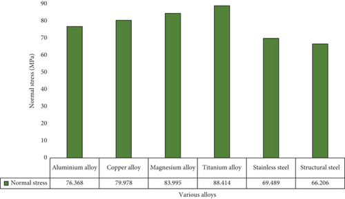
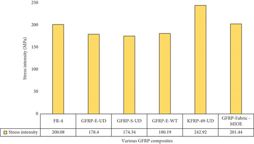
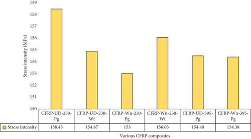
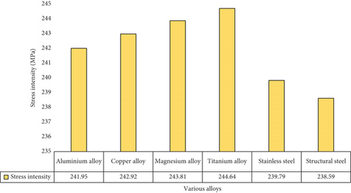
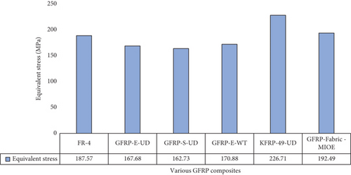
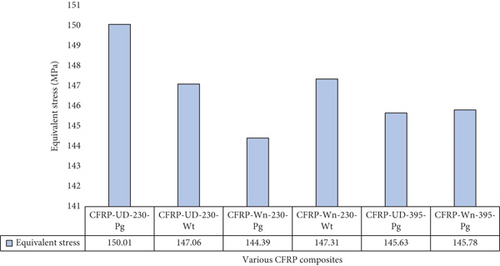
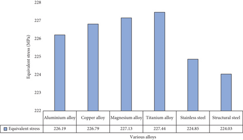
From the graphs, it can be observed that carbon fiber–based composites perform better than that of glass fiber–based composites and alloys in the respective operating conditions. Especially, CFRP-Wn-230-Pg showcased the best performance by having the lowest equivalent elastic stress acting on it with a value of 144.39 MPa followed by CFRP-UD-395-Pg with 145.63 MPa of elastic stress acting on it which is considerably lower than all the other materials, whereas KFRP-based composite’s total deformation is comparatively lower than all the other materials with a deformation of 0.20509 mm. This is due to the varying mechanical properties of each material. The lower deformation is caused by a higher modulus of elasticity.
3.2.2. BC—60 m/s With 180,000 RPM
Relevant results for the boundary condition of inlet velocity 60 m/s with 180,000 RPM are revealed in Figures 35 and 36. The results based on the factors of total deformation, normal stress, equivalent stress, stress intensity, and strain energy on the respective materials are represented graphically in Figures 37, 38, 39, 40, 41, 42, 43, 44, 45, 46, 47, 48, 49, 50, 51, 52, 53, and 54.
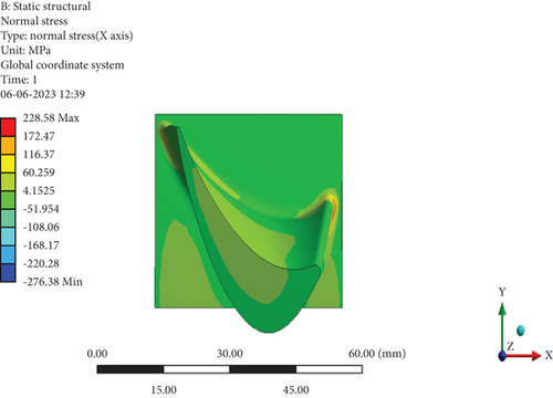
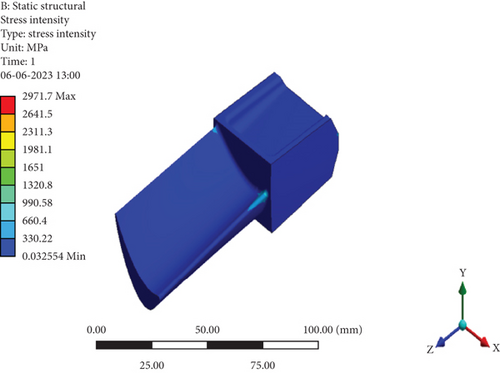
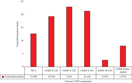
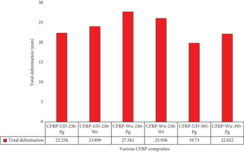
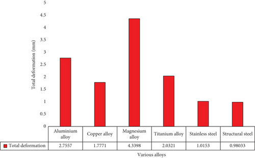
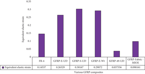
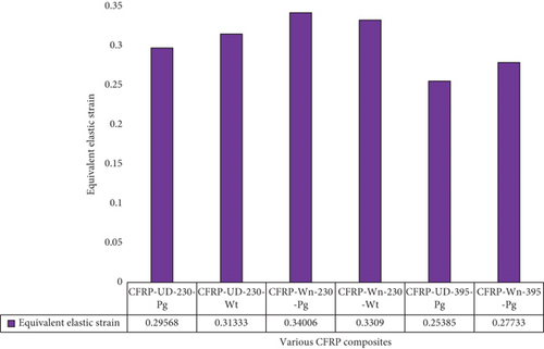
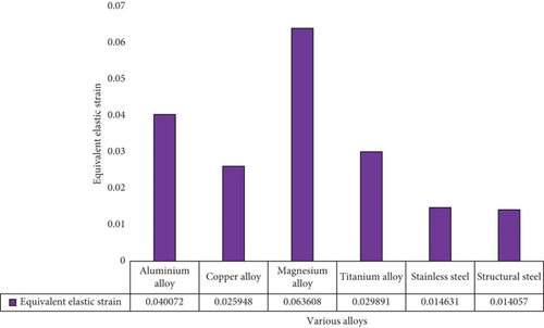
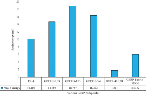
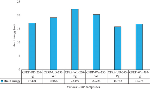
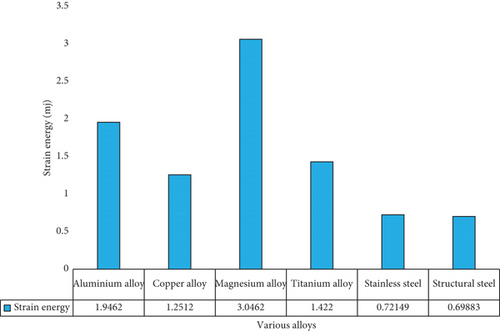
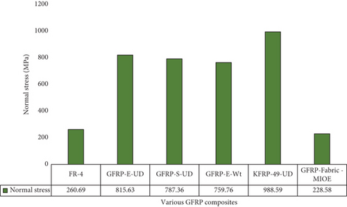
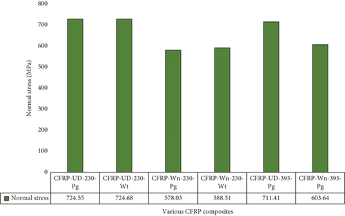
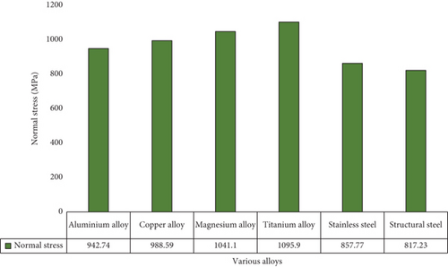
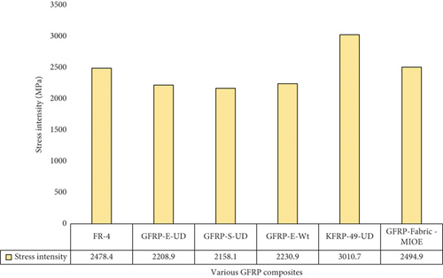
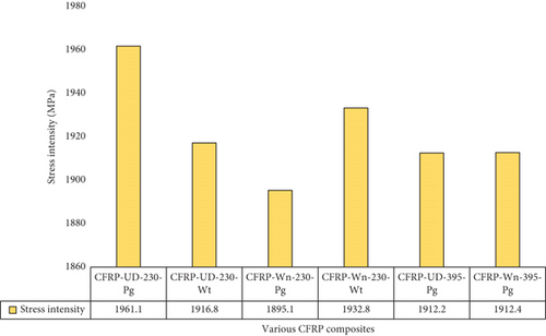
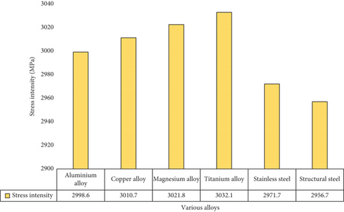
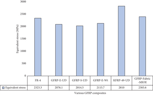
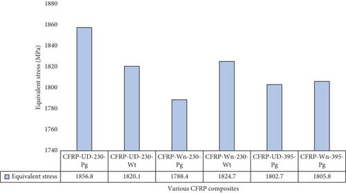
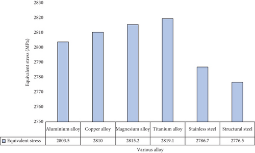
From the graphs, it can be observed that carbon fiber–based composites perform better than that of glass fiber–based composites and alloys in the respective operating conditions. Especially, CFRP-Wn-230-Pg showcased the best performance by having the lowest equivalent elastic stress acting on it with a value of 1788.4 MPa followed by CFRP-UD-395-Pg with 1802.7 MPa of elastic stress acting on it which is considerably lower than all the other materials. This is due to the composites’ orthotropic nature, where each direction of the composites will undergo varying stresses; the material which can resist this stress in all three stresses will be the better performer. In contrast, KFRP-based composite’s total deformation is comparatively lower than all the other materials with a deformation of 2.5721 mm. This is due to the varying mechanical properties of each material. The lower deformation is due to higher modulus of elasticity and higher compressive and tensile strengths.
4. Conclusions
A common technological component of UAVs now is SGT engines. The SGT compressor’s axial flow blades are the primary focus of this investigation. An individual blade used in the axial flow compressor of the UAV-specific SGT engine is the primary focus of this investigation. After a thorough investigation of the design blades is completed via a literature survey, the conceptual design of compressor blades is carried out in 3DEXPERIENCE software. In the first stage, a CFD analysis is performed on the axial flow compressor blade designed for UAVs operating at high altitudes for long periods of time. An FSI-based computational method has been fed with measurements of the compressor blade’s aerodynamic pressure and velocity distributions. Compressor blades constructed from composite materials undergo a structural integrity evaluation using FSI methods. Epoxy-based CFRP, GFRP, and KFRP have all been the subject of extensive research into their structural integrity. This research lays solid groundwork for improving unconventionally made axial flow compressors in the future.
In this research, an FSI analysis was performed on a blade of an axial flow compressor using ANSYS 17.2 software. Twelve materials are put through a thorough analysis for their potential use as compressor blades. With the use of cutting-edge modeling technology, 3DEXPERIENCE, a computational model of the compressor blade’s conceptual design, was constructed and used in the evaluation of CFD and FSI. An axial flow compressor blade subjected to typical aerodynamic boundary conditions is used in a grid convergence test. FVM is used as the method of solving by the computational solver. FSI calculations are performed on a compressor blade under aerodynamic loading circumstances to evaluate different composite materials. The use of CFRP in UAV compressor blades shows promise. CFRP’s extended durability and high-road-bearing capabilities are two of the main reasons for its popularity. When compared to its rivals, the CFRP-UD-Wet material clearly outperformed its rivals. Based on the results of this study, the optimal material for UAV compressor blades came out to be Epoxy-CFRP-UD-Wet. In the future, the authors aim to enhance the aerodynamic and structural performances of the compressor stage by implementing partially moveable stator vanes.
Conflicts of Interest
The authors declare no conflicts of interest.
Author Contributions
Conceptualization: Sandhiya Chandrakumar and Shyam Sundar Jayakumar; methodology: Beena Stanislaus Arputharaj, Parvathy Rajendran, Darshan Kumar Jayaram, Arul Prakash Raji, Arun Bhuvendran, Senthil Kumar Madasamy, Arunkumar Karuppasamy, and Vijayanandh Raja; software support: Senthil Kumar Madasamy, Arunkumar Karuppasamy, and Vijayanandh Raja; validation: Darshan Kumar Jayaram, Arul Prakash Raji, and Arun Bhuvendran; formal analysis: Beena Stanislaus Arputharaj, Parvathy Rajendran, and Darshan Kumar Jayaram; investigation: Beena Stanislaus Arputharaj, Parvathy Rajendran, Darshan Kumar Jayaram, Arul Prakash Raji, Arun Bhuvendran, Senthil Kumar Madasamy, Arunkumar Karuppasamy, and Vijayanandh Raja; resources: Vijayanandh Raja and Parvathy Rajendran; data curation: Senthil Kumar Madasamy, Vijayanandh Raja, and Parvathy Rajendran; writing—original draft preparation: Senthil Kumar Madasamy, Vijayanandh Raja, and Parvathy Rajendran; writing—review and editing: Beena Stanislaus Arputharaj, Darshan Kumar Jayaram, Arul Prakash Raji, Arun Bhuvendran, and Arunkumar Karuppasamy; supervision: Senthil Kumar Madasamy, Vijayanandh Raja, and Parvathy Rajendran; project administration: Senthil Kumar Madasamy, Vijayanandh Raja, and Parvathy Rajendran; funding acquisition: Vijayanandh Raja. All authors have read and agreed to the published version of the manuscript.
Funding
For this research, no outside funding has been provided. This study has been performed based on the authors’ interests, and it makes use of the computational resources and experimental resources from the authors’ working institutions only.
Open Research
Data Availability Statement
The authors confirm that the data supporting the findings of this study are available within the article.


