Research on Autodocking Control Technology of the Propellant Umbilical Connector of Launch Vehicles
Abstract
Aimed at the unattended requirements of the heavy launch vehicle filling and launching support system, this paper focuses on the propellant filling and discharge automatically. This paper adopts the parametric variable frequency and amplitude variation equation to simulate the motion of the launch vehicle under wind load conditions. The equivalent spring damping model is used to simulate the real flexible umbilical arm of the rocket. In this paper, the compound active disturbance rejection control and robust integral sign control (CADRCRISC) method is proposed, including feedforward compensation control, linear feedback control, robust control, and extended state observer (ESO) control. This method can adapt to external disturbances and achieve high-precision follow-up control, which is verified through experiments and simulations. The method can adaptively realize fast-following responses and regulate against any disturbance. The research on the automatic docking control technology of the combined connector is of great significance to the unattended launch support system for heavy launch vehicles. Besides, the control method proposed in this paper can be applied in other similar automatic docking applications.
1. Introduction
At present, automatic docking technology is widely used in national defense aerospace and civil industry. Before launch, the launch vehicle needs to be filled with propellant, and its interface equipment between the rocket and the ground is often called the umbilical connector. At present, umbilical connectors are often docked manually without automation. With the improvement of the rocket carrying capacity, the weight of the umbilical connector is gradually increasing, especially for the requirement of secondary docking. The motivation of the research proposed in the paper is to improve the efficiency and safety of the rocket launch. The automatic docking technology is of great value to the safety of equipment and personnel and to reduce the labor intensity and participation of personnel. In fact, the umbilical connector for rocket docking is on a moving base, and the amplitude and frequency of the rocket motion under wind load are not fixed, which can be regarded as an external disturbance. Therefore, this is a servo control problem for moving bases and targets with external disturbance.
In this paper, the compound active disturbance rejection control and robust integral sign control (CADRCRISC) method proposed in this paper is used for the follow-up docking of umbilical connectors. On the one hand, the system can overcome external disturbances and achieve high-precision, stable follow-up by setting an extended state observer (ESO) to observe the input and output of the actual system. Another innovation of this article is the variable frequency and amplitude parameterized equations proposed to simulate the action of rockets under different wind loads, which make the validation easier in practical applications. However, the overall idea is based on visual noncontact measurement, and controlling the automatic docking equipment can automatically realize a fast-following response and regulate against any disturbance.
2. Materials and Methods
2.1. Literature Review
With the continuous development of heavy launch vehicles [1, pp. 20–23], the types and weight of umbilical connectors have increased [2, pp. 137–146], and the requirements for personnel operation intensity and safety have gradually improved [3, pp. 31–35]. The demand for automatic docking technology [4, pp. 41–44] of heavy launch vehicle umbilical connectors [5, pp. 1001–3881] has become increasingly urgent. Due to the importance of automatic docking technology in the launch support system of launch vehicles, extensive research has been carried out on the automatic docking technology gradually. Some Russian series rockets use automatic docking technology, which mainly relies on the manipulator to achieve their docking execution. Their refueling and docking devices are located in the launching tunnel, so there will be no large relative motion conditions [6, pp. 1232–1239]. Therefore, it meets the use requirements by using the static automatic docking technology. Most American rockets use zero-second drop-off technology, and it is not used widely of the automatic docking technology to achieve automatic docking of their propellant refuel system. In recent years, American rockets have paid attention to the development of new technologies and gradually developed unattended ground support systems. At present, no application examples of automatic docking technology have been publicly reported by American rockets. In 2005, based on the new generation umbilical cord connection technology of NASA, Kennedy Space Center launched the “Remote Intelligent Umbilical Cord Docking System” to replace the traditional umbilical cord docking system. As shown in Figure 1, the rocket umbilical cord connector automatic docking device developed by Kennedy Space Center improves the safety of personnel and equipment through automatic docking and reduces operation, failure modes, and launch preparation time. In 2007, the United Space Federation of the United States announced the Automated Ground Umbilical Systems (AGUS) project, which aims to minimize the operation time and labor for manual docking of the ground umbilical system while maintaining its reliability. This project has optimized the design of the Saturn, Shuttle, X-33, and Atlas V umbilical cord system and mechanism. In 2012, the United States designed a linear fitting device for the ARES1 umbilical cord and tested it at Kennedy Space Center.
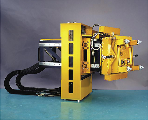
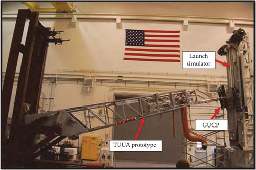
In China, Beijing Aerospace Launch Technology Research Institute [7, pp. 25–28] has carried out multiround iterative optimization design for automatic docking technology [8, pp. 65–71]. Wang, Shi-dong, and Xue-jun [9, pp. 89–92] have analyzed the influence of the stiffness of the swing bar installed on the automatic docking accuracy. Research [10, pp. 11–15] shows that the control accuracy is related to the stiffness of the flexible umbilical arm. Yong-yi et al. [11, pp. 116–121] studied the automatic docking test and error statistics of robots in a flexible rectangular coordinate system. Nanjing University of Science and Technology has designed and studied the connector pose compensation mechanism. Shanghai Jiaotong University [12, pp. 485–490] has studied sensing devices for automatic docking. The sensor system adopts two accurate CCDs as the automatic visual positioning device to measure the position and the posture between the manipulator of the robot and the objective in case of a good visual condition. Besides, as compensation for the shortage of the vision system, the tactile sensor system, which is like the probe of an insect, is also employed. The precision of the proposed vision and tactile sensory system is analyzed. Zhang and Yun [13, pp. 60–62] studied the docking technology of autorecharging a security robot, which is used for robot docking. Several experiments are made to prove the feasibility of the method. Wei and Li [14, pp. 64–66] conducted autocharging tests which show that the precision of docking is prior to ±5 mm. Aiming at the problem of passive adjustment of traditional docking methods without the support of field-measured data, the optimization feedback control technology of the fuselage process was studied by Zhao et al. [15, pp. 883–891] based on the digital twin virtual reality combination technology. A digital twin system integrating the redundant control algorithm and the process optimization strategy was built. A connector position and pose compensation mechanism are designed, the spring parameters are optimized, and the position and pose deviation between the connector docking device and rocket in the process of autodocking and follow-up are eliminated. The related technical indicators are verified, the design parameters are determined, and the objective function is optimized by Bao-ping, Hua, and Qing [16, pp. 80–83]. A docking controller based on model predictive control (MPC) is designed by Ling et al. [17, pp. 431–442] to solve the problem of position tracking and attitude synchronization in the process of docking a micro-nano satellite with a tumbling noncooperative target under multiple constraints. The PID and fuzzy control methods have been applied in the LNG upload arm by S. Liu, Xu, and Z. Liu [18, pp. 57–64]. Yongchun et al. [19, pp. 12–68] discuss the development process of rendezvous and docking control technology in the implementation of CMS three-step strategy, analyze the development requirements of the follow-up tasks, and give some suggestions for the future development of the control technology. In actual visual servo control, there is much literature on vibration research [20, pp. 77–96]. The literature indicates analyzing vibration suppression through model prediction and conducting related control technology research [21, pp. 51–59]. There are also methods in servo control to avoid and suppress vibration by setting servo parameters [22, pp. 23–45]. The literature [23–26] indicates that servo control also includes identification and testing of residual vibration, and parameters can be adjusted online [27]. A lot of technical research has been conducted on rocket propellant connectors [28–33]. There are also relevant literature studies on hydraulic docking mechanisms, including valve-controlled cylinders [30, 34–37]. Of course, some designs for docking mechanisms are also important [38, 39]. Of course, there are many outstanding articles on visual research [40, 41]. To gain a clearer understanding of the current research status, we have compiled a brief summary of the citations, as shown in Table 1.
| Reference number | A brief methodology | Highlights | Limitations |
|---|---|---|---|
| 1. | Focusing on autodocking characteristics and the research and development practical condition of Russia’s “Trestle roosted” and the United States’ “Rocket roosted” technology, summed up and analyzed the formation of this decisive technology. | It drew out the domestic idea of “the amphibious synthesis” docking technology and has forecast the autodocking trend of research and development. | The method is described, and the specific solution needs further research. |
| 2. | Mathematic models of matching variations of commonly used geometric characteristics are established, including point-set matching, line alignment, plane matching, surface matching, and geometrical constraints. | Propose docking methods for large components. | Not involving specific control theories for specific application scenarios. |
| 3. | The design of involved actuators and compliant mechanisms is explained, and ADAMS is adopted to verify that the designed workspace of the 3-UPU-actuator can meet the need of connecting the panel’s movement under wind loads. | Establish a dynamic model. The results can be a reference for future deep studies on the umbilical system of launch vehicles. | No physical prototype or control theory–related description. |
| 4. | Aiming at the implementation of propellant filling automation for carrier robot, a special robot is designed for autodocking with a rocket and autoseparating from the rocket. The robot can trace the rocket in real-time using a SCARA manipulator and LIDAR localization system. The compliant docking and separating mechanism are mechanical carriers for the connecting robot and rocket. | This paper provided a docking method. | The docking device has a small payload and a small range of movement, making it suitable for ground use. |
| 5. | A method of automatic docking of rocket parts was introduced by using a laser tracker to collect data, combining sliding mode control with synchronous control, and controlling the support frame car designed independently by a workshop to adjust the attitude of the parts. | Provided a workshop docking method. | Not suitable for high-altitude rocket applications. |
| 6. |
|
A method based on laser contour sensor and CCD image sensor is proposed. | The paper describes the measurement method but does not propose a control method. |
| 7. | The control flow of the autodocking system is proposed, and the simulations reveal that the requirement of the autodocking system can be met. | The control flow of autodocking is proposed. | Specific control methods and issues that should be considered, such as interference, were not considered. |
| 8. | This paper proposes some advice about the application of automated mating techniques on internal launch vehicles, which have considered their overall technique characteristics. | Described the international status of automatic docking of rocket connectors. | Belongs to a review document, without specific methods or experimental research. |
| 9. | Aiming at the scheme of a hydraulic motor-driven three-degree-of-freedom robot, the mathematical model of the system is established, the stability of the system is judged, and the control error is analyzed by simulation analysis. | This paper can provide a reference for the design of automatic docking devices of connectors and also provide technical reference for other similar occasions with docking requirements. | The control model is relatively simple, and factors such as external interference and wind load are not considered. |
| 10. | This paper describes the impact of pendulum stiffness on docking control accuracy. | System design should consider the influence of pendulum stiffness on control. | The paper does not propose specific methods for docking control under poor stiffness. |
| 11. | Through the analysis of the mechanism type and characteristics of industrial robots, an umbilical connector’s autonomous mating system scheme based on the flexible rectangular robot is presented, and then the practical umbilical connector’s autonomous mating experimental system based on the flexible rectangular robot is developed. | This paper provided an umbilical connector’s autonomous mating system. | No specific control details and considerations were provided. |
| 12. | The sensor system adopts two accurate CCDs as the automatic visual positioning device to measure the position and the posture between the manipulator of the robot and the objective in case of good visual condition. | Provided a noncontact measurement solution for docking systems. | No relevant control methods were provided. |
| 13. | Autorecharging of security robot is studied, and infrared docking technology is introduced which is used for robot docking. | Provided a mobile docking solution. | Experimental design and application are applicable to the ground. |
| 14. | Infrared sensors and cameras are used to complete the process of cleaning the robot docking to the charging dock. | Camera covers the shortage of low precision of infrared sensor, and infrared sensor covers the shortage of small vision of the camera. | Suitable for ground applications. |
| 15. | A digital twin system integrating redundant control algorithms and establishing a process optimization strategy. The feedback accuracy of the measurement optimization process clarifies the optimization based on on-site measurement data. | The application of digital twin technology in docking. | The system is complex and suitable for ground docking situations. |
| 16. | The position and pose deviation between the connector docking device and rocket in the process of autodocking and follow-up is eliminated. | The article proposes a flexible adaptive mechanism that does require. | Further design is needed for the scope of adaptation of the institution. |
| 17. | A docking controller based on model predictive control (MPC) is designed to solve the problem of position tracking and attitude synchronization in the process of docking a micro-nano satellite with a tumbling noncooperative target under multiple constraints. | A docking controller based on model predictive control (MPC) is designed. | The method is feasible in space docking but may not necessarily be applicable in actual high-altitude ground conditions. |
| 18. | The fuzzy PID control method is introduced in the LNG arm control. | The fuzzy control method is applied in the LNG arm control. | The method used in the LNG scenario is relatively simple, without vibration or external disturbances, and the speed is also relatively slow. |
| 19. | The history and technological characteristics of foreign manned space rendezvous and docking are reviewed, and the key technologies needed to be settled in the development of China space rendezvous and docking are analyzed. | The paper proposed the docking test flights of Shenzhou spaceships with Tiangong target spacecraft. | Further research is needed on the automatic docking technology of propellant umbilical connector. |
| 20. | The article provides a scaling and bandwidth parameterization-based controller tuning approach. | The control method and bandwidth parameterization are proposed in the paper. | A method has been proposed, but for existing problems with moving bases and dynamics, a composite control method is needed. |
| 21. | Research on sliding mode predictive vibration control of rigid-flexible coupled robots was conducted in the article. | The paper proposed a predictive vibration control method. | Parameter adjustment can be applied to flexible docking based on structural characteristics. |
| 22. | The article proposed to suppress vibration by setting the parameters of the servo driver. | Provides a way to solve or suppress vibration. | Parameter settings need to match the structure design. |
| 23. | The article proposes a method for suppressing vibration in large-scale robotic arm motion. | The vibration suppression of large-scale robotic arm motion can be referenced. | The design of a large-scale robotic arm needs to match its structure. |
| 24. | The article proposes a sliding mode control for vibration suppression. | Sliding mode control is a commonly used control method, especially in the servo field. | Sliding mode control needs to match the actual model. |
| 25. | The article proposes a docking control strategy between noncooperative targets. | A reference for space docking. | External disturbances such as ground wind loads may require more consideration in the launch field. |
| 26. | The article provides a method for suppressing docking vibration through experimental modal analysis. | The experimental modal analysis is an effective way. | Experimental modal analysis may not be applicable to all situations to analyze vibration suppression. |
| 27. | The article proposes using a time delay filter to suppress vibration. | Time-delayed filters may be a very effective method for suppressing vibration. | Time delay filters may have difficult parameter adjustment and may not be suitable for situations that require fast response. |
| 28. | The article provides a control system design method for the detachment of storage box connectors. | The design method of the control system for the detachment of the storage box connector can be referenced. | Belonging to sequential control, servo motion can be further considered. |
| 29. | The article provides a target recognition method that can be used for visual servoing. | The target recognition method of visual servoing can be referenced. | Visual quick responsiveness needs to be considered. |
| 30. | The article proposes a connector separation testing system. | The separation testing system can be used as a reference for reference. | The specific control of the separation part of the connector can be further studied. |
| 31. | An overall description was provided for the design of rocket propellant connectors. | The design of rocket propellant connectors can be used as a reference. | Belongs to a review article. |
| 32. | Consider a connector separation design approach. | Provide a reference for connector design. | Related controls can be further discussed. |
| 33. | Design of a docking application for gas–liquid connectors. | Proposed a three-degree-of-freedom docking method. | No specific docking control method. |
| 34. | The article provides a fuzzy control method. | The article provides a specific application scenario for a fuzzy control method. | Specific fuzzy control parameters can be further explored. |
| 35. | The article provides a control method for an electrohydraulic servo vibration table. | Provide a reference for the control of electrohydraulic docking actuators. | The control parameter settings can be further discussed. |
| 36. | The article focuses on the research of motion optimization and trajectory tracking control for six-degree-of-freedom serial robots. | The motion optimization and trajectory tracking control can be used as a reference. | Trajectory tracking and servo speed need to be combined. |
| 37. | The article proposes a new design method for resonant mode suppression controller in servo systems. | This new design method for resonant mode suppression controller in servo systems can serve as a reference. | Further integration of theory and practical application is needed. |
| 38. | Time-varying output-constrained adaptive filtering control for uncertain electrohydraulic servo systems | Provided a constraint adaptive filtering control method. | The scope of the application of adaptive filtering can be further described. |
| 39. | The article provides a docking control strategy. | There are many descriptions of automatic docking control strategies. | No specific control method. |
| 40. | Propose a bandwidth adjustment parameter method. | A very useful LESO parameter tuning method. | The range of parameter values and their impact can be further described. |
| 41. | Neither deep learning nor classical image-processing algorithms alone can detect and count bunches in both periods. | The article describes the application of deep learning in practical engineering, allowing readers to see its potential. | The research in the article is very insightful and worthy of readers’ in-depth learning. |
| 42. | After extracting cracks through semantic segmentation, the paper proposed to use the method of the inscribed circle of crack outline to calculate the maximum width of the detected crack image and to convert it into the actual width of the crack. The maximum relative error rate was 11.22%. | The results demonstrated the potential of innovative deep learning methods for dam crack detection. | The research in the article is of great practical value and is worth readers’ in-depth learning. |
3. Methods
3.1. Analysis and Methods
The automatic docking system for the umbilical connector of the propellant refuel system involves multiple disciplines such as machinery, electricity, gas circuits, machine vision, and intelligent algorithms. Moreover, the flexible moving base of the umbilical tower, the change of pipeline load during the propellant filling and discharge process, and the motion under wind load have complex nonlinear dynamic coupling characteristics. It faces technical difficulties such as nonlinear interference and unmodeled parameters such as the flexible umbilical arm of the rocket, the motion of the rocket, and the pipeline variable load.
In this paper, based on the intelligent algorithm for vision location, the matrix target is fixed on the moving rocket under wind load conditions. The camera is fixed to the docking mechanism. The position of the moving rocket is located through the real-time computer. The motion of the rocket under the wind load is simulated using the parametric variable frequency and amplitude variation equation. It is acknowledged that the control method of ADRC has certain research and applications for unmodeled disturbance conditions. However, there are difficulties in parameter tuning for this control method. This paper studies the automatic docking technology based on CADRCRISC, which includes feedforward compensation control, linear feedback control, robust control, and ESO control. Moreover, in order to verify the effectiveness of the control system, the servo control is carried out under different working conditions.
As shown in Figures 2 and 3, the automatic docking control system mainly includes the motion of the rocket simulation system, vision computer, control computer, and rapid prototype system. The rocket body simulation control system is used to simulate the rocket motion under different wind load conditions of variable frequency and amplitude.
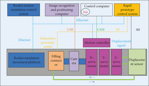
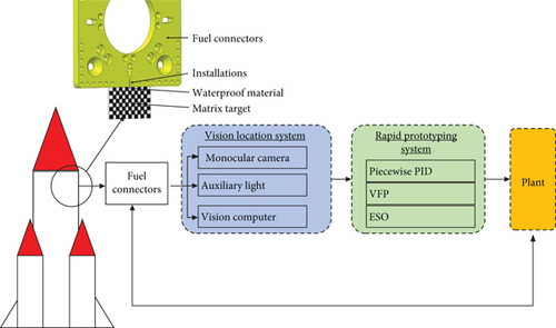
The vision computer collects the target information of the moving target, which is on the surface of the rocket. The relative motion between the launch vehicle and the automatic docking device is calculated by the high-speed camera on the docking mechanism in real-time and serves as the real-time feedback information of the servo control.
The control computer is connected to the rapid prototype through Ethernet, and the control model is quickly loaded into the real-time control system to follow up on the motion of the rocket. At the same time, it cooperates with the high-pressure air source to realize the valve-locking action so as to realize the “one-key” automatic docking and separation process of the umbilical connector.
The umbilical connector is installed on the six-degree-of-freedom Stewart platform. Through noncooperative targets and machine vision, real-time position and attitude information of the rocket at the launch station is obtained, and the Stewart platform is controlled to achieve horizontal, vertical, and forward propulsion motion.
According to the control function requirements, the overall control circuit of the automatic docking mainly includes three parts: the dynamic follow-up control part, the Stewart platform control part, and the electric cylinder closed-loop control part.
In the dynamic follow-up control part, the CADRCRISC servo control method mainly includes piecewise PID control, nonlinear integral robust control, feedforward control, and ESO. In order to compare and verify the control accuracy, the algorithm can be independently tested under different conditions. The segmented PID mainly achieves the smoothness of visual servo follow-up. Feedforward compensation is used to improve the dynamic characteristics of the system.
The control of parallel platforms mainly involves inverse kinematics, which accumulates and calculates the length that the electric cylinder needs to reach in real time after receiving the follow-up pose control variables. This serves as the input control variable for the closed-loop position of the electric cylinder.
The Stewart platform control part mainly involves inverse kinematics, which accumulates and calculates the length that the electric cylinder needs to reach in real time after receiving the follow-up control.
The closed-loop control of the electric cylinder is formed by PID and feedforward after receiving the length of the servo cylinder.
The modeling of the automatic docking control system is shown in Figures 4 and 5. The servo control system includes a position loop, speed loop, and current loop to achieve three-loop control. The symbol PLANT in the control block diagram represents the controlled object.


In Figure 4, x1, x2, x3, x4, x5, x6 is the displacement control variables of the six leg targets on the Stewart platform.
3.2. Control Methods
In the formula, Pn is the number of magnetic poles of the motor. Ld and Lq are the inductance. Pn is the magnetic flow. The id and iq are the electric currents.
In the formula, Tem is the electromagnetic torque. J is the equivalent moment of inertia on the motor shaft. ω is the mechanical speed of the motor. TL is the load torque. B is the viscous friction coefficient of the motor.
The vector control adopted decouples the AC and DC axis currents of the motor. At this time, the electromagnetic torque is proportional to the current, and the control of the torque is transformed into the control of the current, that is, the control characteristics of the DC motor. The following control equation is summarized.
The control of each cylinder is shown as follows. Gp(s) is the position control loop. Gv(s) is the speed control loop. Gi(s) is the current control loop. KTp is the torque coefficient. ip is the ratio of the electric speed to the linear speed. bp is the steady gain of the speed loop.
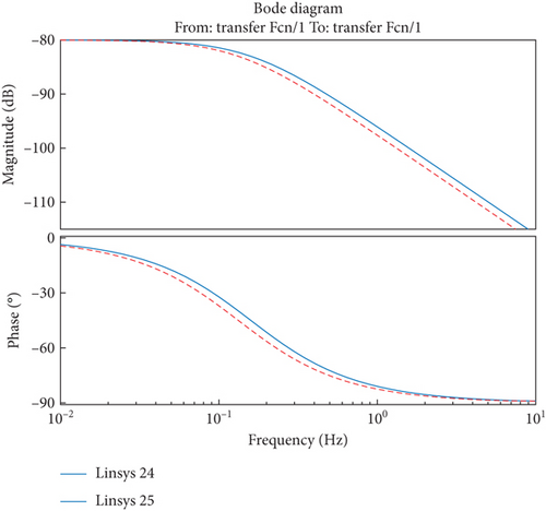
Speed feedforward control is to realize fast follow-up control by compensating the output control with the given speed feedforward coefficient.
3.3. Kinematic Methods
The SPS parallel mechanism (Stewart platform) is connected to the upper and lower platforms by six branches, each with a ball joint at both ends and a moving pair in the middle. The displacement change of the electric cylinder causes a change in the posture of the upper platform. The relative pose of the upper platform can be obtained through the visual positioning system. The length of each electric cylinder can be calculated by inverse kinematics solution.
First, establish a static and dynamic coordinate system. The static coordinate system O-XYZ is located on the lower platform, and the dynamic coordinate system O′-X′Y′Z′ is located on the upper platform. The static and dynamic coordinate system XYZ-direction is consistent, and the Z-axis of the static coordinate system passes through the O′ point.
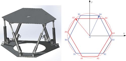
In the formula, α, β, and γ are the rotation angles around ZYX. R is the cosine matrix, and O is the translation matrix. XA, YA, and ZA represent static platform coordinates. XB, YB, and ZB represent static platform coordinates. XB, YB, and ZB represent the dynamic coordinate system.
In this project, there are no singular points in the workspace of the Stewart platform. The Newton–Raphson iteration method is used to achieve forward kinematic solutions. The idea is to use the current length to calculate the current pose. The initial pose and inverse kinematics solution are used to calculate the corresponding rod length and solve the Jacobian matrix.
4. Simulation
In order to verify the control method, optimize the control parameters, and analyze the sensitivity of parameters, a cosimulation model of an umbilical connector automatic docking device is established based on the Modelica language. Figure 8 shows the cosimulation model of the autodocking system of the launch vehicle umbilical connectors, including the multibody dynamics model, motor model, ball screw model, machine vision model, and control strategy model. As shown in Figure 8, the multibody dynamic model for the autodocking system of the launch vehicle umbilical connectors is mainly composed of three moving pairs.
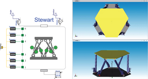
When the rocket is transferred vertically to the launch tower, the motion of the rocket is the variable frequency and amplitude under the wind load condition. Therefore, it is necessary to simulate the motion of the rocket to verify the ability of the control method under different conditions. The variable frequency and variable amplitude curve equation is proposed to enable the three-degree-of-freedom motion simulation platform to simulate variable frequency and variable amplitude conditions.
The four functional curves include the frequency conversion and amplitude variation curve, index amplitude variation attenuation curve, frequency conversion curve, and isochromatic amplitude variation curve. The frequency conversion and amplitude variation functions can be superimposed according to the weight of the three function curves.
4.1. Amplitude Index Attenuation Curve
4.2. Frequency Conversion Curve
The frequency conversion curve can be realized by splicing several complete sinusoidal curves, but considering the influence of frequency change on the phase, in order to ensure the continuous change of the signal, the frequency switching point must be converted at the time of zero phase.
4.3. Isochromatic Amplitude Curve
5. Results
5.1. Experiment Setup
As shown in Figure 9, the autodocking system of the launch vehicle umbilical connectors is composed of the autodocking platform, the platform to simulate the motion of the rocket, the monocular camera, the pneumatic transmission, the rapid prototype system, the vision computer, etc. The monocular vision feeds back the position and attitude deviation information to the rapid prototype and sends the control command to the autodocking drive controller to adjust the autodocking device’s attitude maintenance. The key technical indicators are shown as follows. The three-axis motion range is as follows: X-axis ± 150 mm, Y-axis ± 150 mm, and Z-axis ± 120 mm. The three-axis motion speed is as follows: 100, 100, and 50 mm/s. The visual camera is installed at the end of the docking device, and the target is installed on the surface of the rocket. The relative position and attitude between the rocket and the docking device collected by the camera are transmitted in real-time (10 ms) to the motion control computer for real-time follow-up control.

5.2. Test Items
- 1.
As shown in Table 2, the comparison test of simulation and test parameters under different speeds (30–100 mm/s).
- 2.
The comparison test of different control methods (piecewise PID, velocity feedforward compensation control VFP, piecewise PID+speed feedforward compensation control VFP+ESO, and piecewise PID+speed feedforward compensation control VFP+ESO+robust integral control) at different servo speeds (30–100 mm/s).
- 3.
Full process tests such as automatic docking and separation under the condition of variable frequency and amplitude movement of the rocket.
| Amplitude (mm) | Frequency (Hz) | Speeds (mm/s) | PID (mm) | VFP (mm) | P_sim (mm) | VFP_sim (mm) |
|---|---|---|---|---|---|---|
| 130 | 0.1224269 | 100 | 9.3 | 5.2 | 9 | 4.73 |
| 100 | 0.127324 | 80 | 7.9 | 4.4 | 8 | 4.257 |
| 80 | 0.0994718 | 50 | 5.7 | 3 | 5.1 | 3.5 |
| 50 | 0.1018592 | 32 | 4.2 | 2.4 | 4.6 | 2.7 |
| 80 | 0.063662 | 32 | 4.4 | 2.3 | 4.2 | 2.46 |
| 150 | 0.1061033 | 100 | 9.1 | 5.5 | 9.7 | 4.45 |
| 130 | 0.1224269 | 100 | 9.3 | 5.2 | 9 | 4.73 |
Simulating the disturbance test of the moving base caused by the umbilical arm of the rocket to verify the effectiveness of the control method under the disturbance of the moving base.
6. Results
As shown in Figure 10, it is the comparison of the X-axis in various test conditions of the piecewise PID control algorithm and feedforward control algorithm. It can be seen that the trend of tracking error with tracking speed is consistent between the cosimulation model and the experiment. Therefore, the cosimulation model can accurately simulate the automatic docking device of the real connector. At the same time, it can be seen from the cosimulation and test results that the combination of the feedforward control method and piecewise PID control algorithm is obviously superior to the piecewise PID control algorithm, as shown in Figure 11.
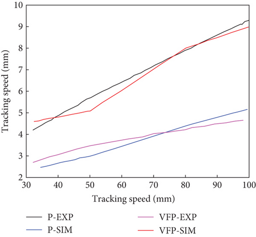
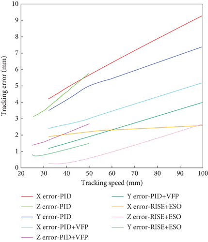
In order to compare the control performance of piecewise PID and CADRCRISC control algorithms including feedforward compensation control, integral robust control, and extended observer control algorithms, five working conditions were tested in three directions, respectively. As shown in Table 3 and Figure 11, it is obvious that the CADRCRISC control is better than the individual piecewise PID. With the increase of the following speed, the tracking error of each control method increases gradually. The feedforward compensation control and the piecewise PID feedback control have significantly improved the accuracy compared with the piecewise PID control method.
| Direction | Amplitude (mm) | Frequency (Hz) | Speeds (mm/s) | VFP+ESO (mm) | RISE+ESO (mm) | PID (mm) |
|---|---|---|---|---|---|---|
| X | 130 | 0.122426881 | 100 | 4.2 | 2.6 | 9.3 |
| 100 | 0.127323957 | 80 | 4.2 | 2.5 | 7.9 | |
| 80 | 0.099471841 | 50 | 3 | 2.2 | 5.7 | |
| 50 | 0.101859165 | 32 | 2.4 | 1.9 | 4.2 | |
| 80 | 0.063661978 | 32 | 2.3 | 1.9 | 4.4 | |
| Y | 120 | 0.132629122 | 100 | 3.5 | 2.7 | 7.4 |
| 120 | 0.106103297 | 80 | 2.8 | 1.8 | 6.7 | |
| 80 | 0.099471841 | 50 | 1.7 | 0.6 | 5 | |
| 50 | 0.159154946 | 50 | 1.6 | 1 | 4.2 | |
| 100 | 0.050929583 | 32 | 1.2 | 0.3 | 3.5 | |
| Z | 100 | 0.079577473 | 50 | 2.5 | 1.5 | 5.8 |
| 100 | 0.047746484 | 30 | 1.6 | 0.7 | 3.7 | |
| 80 | 0.059683105 | 30 | 1.7 | 0.8 | 3.5 | |
| 50 | 0.079577473 | 25 | 1.3 | 0.8 | 3.1 | |
| 80 | 0.049735921 | 25 | 1.4 | 0.8 | 3.1 | |
As shown in Figures 12 and 13, the tracking error of the Y-axis under extreme operating conditions shows that the tracking error of the piecewise PID control method is the largest, and the maximum error value decreases after feedforward compensation control. But there is a sudden increase of signal burr at the moment of change of direction, which is affected by friction damping.
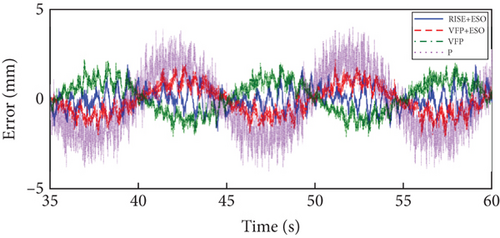
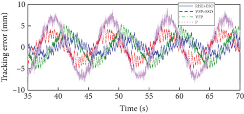
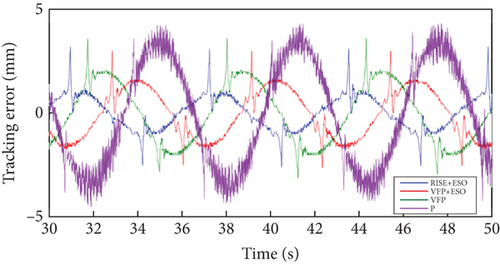
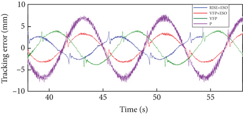
As shown in Figure 14, the accuracy of integral robust control and ESO is higher than that of piecewise PID control and feedforward control due to the inclusion of nonlinear integral robust term and disturbance compensation term.
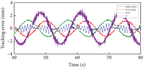
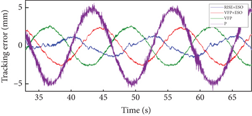
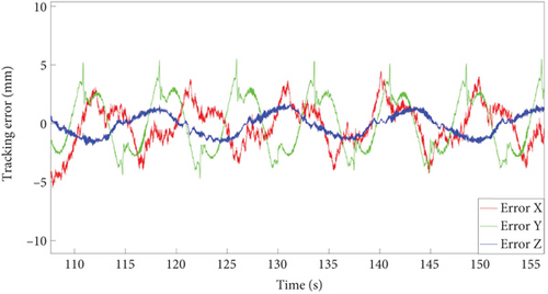
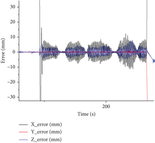
As shown in Figure 15, the tracking error curve under the three-axis extreme working condition shows that there is a sharp increase in the reversing X- and Y-directions. Since the following speed in the Z-direction under extreme working conditions is 50 mm/s, which is smaller than that in the XY-direction, its control accuracy is higher. Moreover, due to the large load in the Z-direction, the overall variation of the tracking error is small, and the jitter is not obvious.
6.1. Analysis of the Rocket Motion Simulated by Frequency Conversion and Amplitude Variation
In order to more realistically simulate the movement of the rocket under the wind load condition, the parameterized variable frequency variable amplitude function is used to control the simulation platform. The simulation platform can realize variable frequency and variable amplitude curve, variable amplitude exponential attenuation curve, variable frequency curve, and isochromatic variable amplitude curve. At the same time, in order to verify the effectiveness of the control method under variable frequency and amplitude variation, the full process test of automatic docking under variable frequency and amplitude variation motion was conducted, as shown in Figure 16.
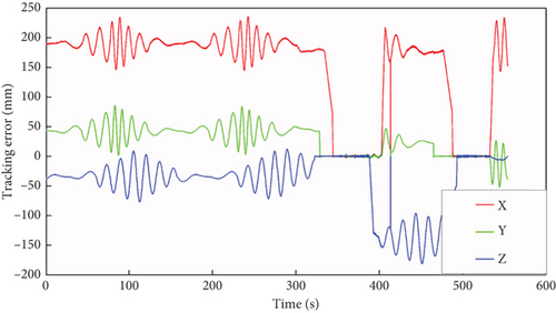
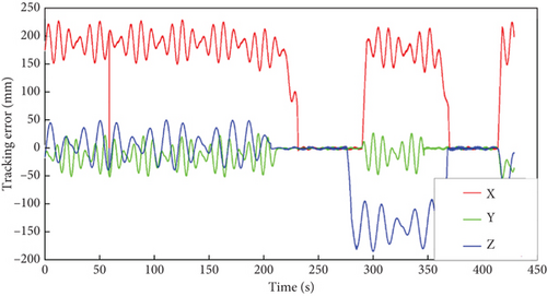

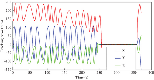
It can be seen from Figure 16 that the parameterized equation can simulate the variable frequency, variable amplitude, and variable amplitude motion of the rocket and can realize following control in three directions. The tracking error is related to the following speed. Figure 16 shows the whole process of docking, including primary docking, automatic separation, and secondary docking.
6.2. Disturbance Analysis of the Moving Base
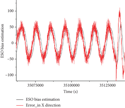
In order to simulate the actual working condition of the moving base caused by the umbilical arm of the rocket with the effect of wind load. The moving base retains the spring damping movement in the X-direction, and the spring moving base cannot move in the YZ-direction. The simulated feed direction moves close to the rocket direction. The docking mechanism can impose a random disturbance in the feed direction during the docking process.
As shown in Figures 17 and 18, the automatic docking control method expands the input and output of the actual observation system of the state observer, actually estimates the system deviation, and adds the deviation estimation control compensation output.
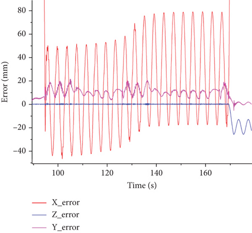
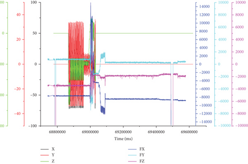
As shown in Figure 19, during the dynamic follow-up process, if the continuous detection error meets the docking accuracy requirements, a docking action is carried out. To prevent damage or deformation caused by excessive force on the rocket when in contact with it, a three-dimensional force sensor is installed on the docking surface. As shown in Figure 19, the force at the docking time is relatively high, and after the docking is completed, the docking force quickly decreases to a small range, meeting the usage requirements.
7. Discussion
The paper mainly focuses on the research of automatic docking technology for umbilical connectors in the rocket propellant refuel system. It is acknowledged that the movement of the umbilical arm and the rocket under the wind load leads to the problem to be a complex nonlinear dynamic coupling system with the moving base and target. Taking the external disturbance into consideration, the CADRCRISC method is proposed in this paper, which includes piecewise PID control, feedforward control, integral robust control, and ESO. A cosimulation model of an umbilical connector automatic docking device is established based on the Modelica language. The control parameters and model parameters were optimized and corrected by comparing them with experimental data. The experimental system is built to simulate the variable frequency and amplitude motion of the rocket under wind load. The experiments of follow-up and autodocking were conducted with the external disturbance based on the CADRCRISC method. The umbilical connector as the interface of the rocket and ground can follow rocket motion and achieve reliable docking. The system can maintain stable follow-up due to the compensation control quantities of robust control and disturbance observer when the disturbance occurs. For comparison, follow-up experiments using only linear feedback control were also conducted. To ensure the system’s follow-up speed, a larger gain coefficient should be selected, which is sensitive to external random disturbances and cannot quickly restore stability. With the increase of the moving speed of the target, the tracking accuracy of each control method shows a downward trend, and the error based on piecewise PID control is the largest. At the same time, due to the large following speed in the XY-direction and the change in friction damping at the moment of reversing, the tracking error curve will have a sudden increase in the signal burr of reversing deviation. The accuracy of the RISE algorithm and ESO is higher than that of piecewise PID control and feedforward control due to the inclusion of a nonlinear integral robust term and a disturbance compensation term. Therefore, the CADRCRISC method proposed in this paper has a good anti-interference effect for those systems with external disturbances that are difficult to measure and model.
8. Conclusions
This paper focuses on the research of propellant automatic docking control technology. Aiming at the existing difficulties, such as the nonlinear dynamic coupling system and the movement of the base and target, the CADRCRISC method that can adapt to certain external disturbances is proposed. The control method is verified through experiments and simulations. Therefore, it can meet the requirements and adapt to the impact of external disturbances under various working conditions. Therefore, the CADRCRISC method proposed in this paper can make the propellant filling connector follow the rocket’s movement stably, even when the umbilical arm of the rocket and the rocket are moving under the wind load. This reduces personnel operations and improves the level of unmanned. Therefore, using the current CADRCRISC control method in practical rocket launch applications can achieve follow-up control. Besides, it can be extended to other follow-up and docking application scenarios. Of course, parameter optimization and adjustment can be carried out according to the bandwidth method or other methods.
Conflicts of Interest
The authors declare no conflicts of interest.
Funding
The study was conducted with a project funded by the Beijing Institute of Space Launch Technology.
Open Research
Data Availability Statement
The data used to support the findings of this study are included within the article.


