Optimizing Power Flow in Photovoltaic-Hybrid Energy Storage Systems: A PSO and DPSO Approach for PI Controller Tuning
Abstract
This paper focuses on developing power management strategies for hybrid energy storage systems (HESSs) combining batteries and supercapacitors (SCs) with photovoltaic (PV) systems. The proposed control scheme is based on proportional-integral (PI) controllers optimized with particle swarm optimization (PSO) and duplicate particle swarm optimization (DPSO) algorithms. The aim is to reduce peak current and the energy management system’s response time while enhancing the system’s stability during the charging and discharging of the HSS under various operating conditions. A comparative study with other tuning methods is presented to demonstrate the effectiveness of the proposed DPSO algorithm in particle duplication, population diversity, and the convergence speed toward the global optimum, enhancing the overall system’s performance. The results demonstrate the feasibility and robustness of the PI − DPSO in providing quick and accurate responses even under variable load, variable solar irradiations, and variable temperature, thus enhancing the dynamic response of the SC and reducing battery stress, resulting in a longer lifespan for the HESS.
1. Introduction
1.1. Background
Renewable energy sources (RESs) have the potential to reduce greenhouse gas emissions and enhance the wellbeing of the Earth by reducing global dependence on fossil fuels. Electricity generation from solar and wind energy sources has experienced an unprescedented growth in recent years [1].
However, solar and wind energy sources are not continuously available and exhibit variable and intermittent energy patterns over different timeframes, which poses a serious challenge to electric power system operator in maintaining a reliable electricity supply [2]. As a result, the need for an energy storage system (ESS) has become increasingly crucial in addressing the issue of supply–demand imbalance over various durations. ESS can help mitigate power fluctuations caused by intermittency of RES, such as wind and solar. ESS are designed to improve the quality and stability of electricity before it is delivered to the load. However, a single ESS has limited capacity to meet all the requirements of a specific application. Therefore, a viable solution is to combine two or more ESS to create a composite hybrid energy storage system (HESS) [3].
The power-sharing control of these various ESS is essential for their integration to exploit of their complementary qualities to achieve a good balance between energy density and extended lifecycle [4–6]. The most common forms of energy storage are electrical, mechanical, and chemical. One of the most critical chemical storage systems is lithium (Li) batteries, known for their high energy density but low power density, resulting in low charge/discharge rates. Supercapacitor (SC) are incorporated into the system to overcome this issue because they have a high power density and can undergo many charge/discharge cycles [7–9].
A HESS configuration with a battery and SC offers fast response, high power and energy ratings, short and long discharging durations, and a fast response. Furthermore, SC helps smooth peak demands and supports the battery during short backup periods [10, 11]. The HESS is interfaced with a bidirectional converter to ensure a two-way power flow [12].
1.2. Literature Review
Several researchers have proposed different control strategies applied to battery/SC. These works are briefly outlined in Table 1.
| Authors | Year | Major findings |
|---|---|---|
| Rocabert et al. [13] | 2018 | This work focuses on the integration of electrochemical batteries with supercapacitors for grid-supporting applications. The wide range of SC working voltage requires a power conversion step to integrate the ESS into a common DC bus, which is why it was suggested a power control loop distributing power flow for optimized performance and grid-frequency support, typically involving a battery bank; however, the power control indicates a slow dynamic response consequently decrease lifespan of the overall system |
| Jaarsveld and Rupert [14] | 2020 | The research presented an intelligent control system for the HESS such as a battery-supercapacitor using the fuzzy logic controller (FLC) approach. However, this approach is sensitive to changes in the model and data parameters and requires a precise system model |
| Augustine, Mishra, and Lakshminarasamma [15] | 2020 | In this research, the authors combined an adaptive droop-based load sharing, maximum power point tracking, and energy management method for photovoltaic (PV)-based DC microgrid systems. It proposes a proportional droop index technique and generates adaptive virtual resistance Rdroop, allowing PV converters to function in either MPP or load-sharing mode. The unified control scheme addresses challenges in stabilizing the DC grid voltage, although it acknowledges the complexity of the design process |
| Khalid [16] | 2019 | This study discusses the major benefits of integrating batteries with SC and highlights their possible uses in microgrid systems. Also, this work is extensive and will serve as a foundation for future research in energy storage technologies and microgrid applications |
| Xie Liu and Yang [17] | 2020 | This paper presents the new topoogie of the converter to ensure the exchange of power between hybrid electric vehicle energy storage connected to the grid system. The proposed control strategies focus on extending the life of the electrochemical battery by directing power fluctuations to the SC, accompanied by related current control strategies |
| Ravada and Tummuru [18] | 2020 | This study describes a nonlinear control mechanism for a PV, battery, and supercapacitor-based DC microgrid. Conventional linear control schemes have been based on a single operating point and supercapacitor voltage regulation. The suggested structure employs an interconnection damping assessment-passivity based controller (IDA-PBC) as an outside loop controller and a finite control set-model predictive control (FCS-MPC) as an internal current controller. The control structure is digitally friendly and overcomes the constraints of linear PI control systems |
| Guentri et al. [19] | 2021 | This work focuses on the EM and control of a PV system with HESS, which combines battery and SC. The control tactics may incorporate are based on conventional and metaheuristic methods, recognizing their shortcomings in terms of performance measures like overshoot and rising time |
| Zamani, Barakati, and Yousofi-Darmian [20] | 2022 | The gases Brownian motion optimization (GBMO) technique was used by the authors to optimize a fractional order PI controller based on filtering. A search strategy with a high accuracy and pace of convergence was introduced by GBMO. The controller is made to regulate an operational HESS in a remote region power supply system that is mostly powered by wind. Nevertheless, the control technique is computationally difficult and time-consuming, making it unsuitable for real-time application |
|
In these works, a model predictive control (MPC) and a basic PI control are employed to regulate the HESS. However, MPC uses a discrete-time model of the system to anticipate the best solution in the next instant, with the present system state serving as the beginning value. The suggested control technique extends battery life by directing power surges to the SC and managing charge-discharge current. Although MPC can increase system performance by anticipating future behavior, it is computationally complex and time-consuming | |
| Shafi et al. [24] | 2023 | This research describes an artificial neural network (ANN)-based technique for estimating hybrid wind-solar resources and power generation by comparing wind speed and sun radiation with real-time data. Temperature, humidity, air pressure, solar radiation, ideal angle, and goal values are all factors considered by the model. To decrease error, it employs a normalization function as well as an iterative strategy that includes the Levenberg-Marquardt. However, the ANN model does not provide optimal and efficient system performance |
| Zdiri et al. [25] | 2022 | This work suggested a sliding-mode control strategy based on artificial neural networks (ANN) for a hybrid PV–battery–SC system. In order to improve the performance and lifespan of the storage system and prevent the complete disconnection of the load during abrupt fluctuations additionally, the DC bus voltage was rapidly regulated, which increased the battery’s lifespan and ensured the PV system’s continuous flow |
| Narasimhulu et al. [26] | 2022 | The goal of the work is to increase battery responsiveness, particularly during overload situations, by designing EM control algorithms that combine ANN with the Aquila optimizer algorithm (AOA). There are four main hunting methods that AOA is known to use, and each offers several unique benefits over the others. Many Aquila are adept in switching between several hunting strategies quickly and effectively, depending on the situation. In conclusion, behind humans, this hawk is perhaps the second-most intelligent and proficient predator. This circumstance served as the main impetus for the proposed AOA. A simulation environment was used to replicate similar tasks. Because it also reduces high-speed dynamic battery charging and discharging currents, the hybrid ANN–AOA technique maximizes benefits while restricting battery discharge current |
| Mohamed and Zyodulla [27] | 2023 | The authors suggested a PV–battery–fuel cell system control strategy. The approach uses the phasor feasible alternative from advanced power systems to provide design assessment. The control strategy uses a genetic algorithm (GA) and an adaptive neurofuzzy inference system (ANFIS) in this approach. While GA was created to address stability and power quality problems inside the microgrid, ANFIS is utilized to gather system data in electrical power and give dynamic frequency response. These controls’ primary disadvantages, however, are their high computational costs, challenging parameter setting, and essential solution representation |
| Fareesa and S.Reddy [28] | 2023 | This study provided an optimal sizing and control that depends on PSO-GA to reduce oscillations in wind power energy and to discover the ideal power and energy capacity of the HESS. PSO outperforms GA in terms of the convergence rate, overfitting, and local optimum. Furthermore, the PSO outperformed the GA since it runs both global and local searches at the same time, whereas the GA concentrates just on global searches. The study places insufficient attention on the control side of the entire system |
| Bacha et al. [29] | 2024 | This study focuses on simulating a stand-alone hybrid system made up of PV, wind turbines, a storage system, and a diesel generator. This research employs optimization algorithms to address practical issues linked to the integration of renewable energy sources into the distribution system. The goal is to establish the appropriate size to minimize power costs and assure the availability of electricity at cheaper and more dependable prices in far rural locations |
| Santosh and Raghuwanshi [30] | 2023 | In this work, flamingo swarm intelligence algorithms are used to simulate and optimize hybrid renewable energy systems with storage. The ideal energy system is built utilizing a revolutionary flamingo swarm intelligence algorithm (FSIA) that takes into account the least amount of technical factors, such as the risk of load loss, economic factors (cost of electricity [COE] with net present cost (NPC)), and environmental factors [CO2 aspects]). To improve energy independence in green buildings, an optimum economic analysis of a hybrid solar system with ESS is conducted using PSO |
| Srilakshmi et al. [31] | 2024 | Using a shunt active power filter powered by solar energy and energy storage systems to address power quality issues caused by power electronic devices and nonlinear loads. The system makes use of a five-level reduced-switch voltage source converter and a neural network-based reference signal generation approach. The system’s purpose is to stabilize the voltage across the DC bus capacitor, reduce overall harmonic distortion, improve power factor, and maintain power management under changing irradiation and load conditions. The system’s effectiveness is evaluated using three test scenarios |
| Vijayan et al. [32] | 2022 | In this work, the authors recommend an ideal PI-controller-based HESS for a DC microgrid that may effectively employ renewable energy sources. To demonstrate their effectiveness, the model makes use of the PI controller and PSO method |
| Annamalaichamy et al. [33] | 2024 | The paper offers a shunt active power filter (SAPF) with a multilayer cascaded H-bridge inverter that use P–Q theory to reduce harmonics in current power systems. The system’s voltage controllers are a PI and an FLC. The proposed aggregated PWM signal-switching circuit balances individual capacitor voltages while minimizing overall harmonic distortion. Simulation and prototype findings demonstrate that the aggregated PWM system outperforms the PI controller |
| Arun et al.[34] | 2024 | Suggests a relay-based automated tuning solution for the predictive PI control system. The procedure entails finding process models using typical relay feedback testing and calculating the eventual benefit. The first order plus dead-time model is used to build and improve the controller’s dynamic component. The ultimate loop gain is established by relay feedback experiments. The controller gain is adjusted to meet the user-specified gain margin criteria. The method’s auto-tuning capability makes it suited for industrial process control application |
1.3. Research Gap and Motivation
Considering the instantaneous variation of both the load and the photovoltaic (PV) plant, as well as the imperative need for a quick response time of the SC to ensure system stability under various operating conditions, relying on conventional methods based on pole placement (PP) for tuning proportional-integral (PI) controllers proves insufficient, resulting in several drawbacks, including a large initial overshoot, sensitivity to controller gains (Kp and Ki), and sluggish response to unexpected disturbances Furthermore, using heuristic approaches like particle swarm optimization (PSO) to improve PI controller settings might finally lead to a local optimum in a high-dimensional environment. This approach has an impoverished convergence rate during the iterative procedure and also in terms of performance.
1.4. Contribution
This paper proposes a new PSO algorithm called duplicate particle swarm optimization (DPSO). This algorithm serves as a heuristic approach to fine-tuning the parameters of a PI controller. The primary focus of this algorithm is to reduce the peak current and effectively address the response time challenges associated with the SCs. The potential benefits of DPSO in ensuring the system’s stability under different operational conditions are discussed. In addition, it is also motivated by its ability to efficiently explore the search space through particle duplication, which can be advantageous for addressing complex problems such as PI optimization, which is demonstrated. In this innovative approach, DPSO is tailored to address the specific challenges associated with the control of static converters in energy storage systems. The algorithm’s unique features, particularly particle duplication, are leveraged to enhance the efficiency and effectiveness of optimizing PI controllers. This approach is expected to bring improvements in system performance, including enhanced stability, more precise control, and potentially increased energy efficiency.
By applying DPSO to PI controller optimization in the realm of static converters, the authors aim to push the boundaries of conventional control strategies. The outcome of this novel application is anticipated to contribute to advancements in the design and operation of energy storage systems, fostering improvements in overall system performance and reliability. One of the best features of DPSO is that it gives the PI controller a great robustness to unexpected disturbances providing quick responses under various operating conditions.
A comparative study with other tuning methods (PP_PSO) is presented to provide empirical evidence on the superiority of the proposed PP_PSO controller in enhancing the performance of the overall system. This comparative study serves to demonstrate the feasibility and effectiveness of the DPSO algorithm introduced to optimize the PI controller, resulting in improved system performance and robustness. In addition, the proposed control scheme can also improve power quality by minimizing the ripples of the power, which can harm sensitive loads, thereby improving power quality.
1.5. Paper Organization
This paper is organized as follows: Section 2 is dedicated to the system description and modeling. Section 3 deals with the EM of the HESS. The HESS control system is explained in detail in Section 4. The design steps of the proposed control strategy are developed in Section 5. Section 6 addresses the sensitivity analysis and the convergence of the PSO and DPSO. Section 7 presents the simulation model and analyzes the results obtained. Finally, Section 8 summarizes the conclusions of the study.
2. Description of the System
Figure 1 shows the schematic design of the system employed in this study, which includes a PV system linked to a HESS via a bidirectional converter in addition to their parameters presented in Tables A1, A2, A3, and A4. The PV generator is linked to a DC/DC converter, and a maximum power point tracking (MPPT) controller based on the Perturb and Observe (P & O) algorithm is utilized to extract the maximum PV energy.
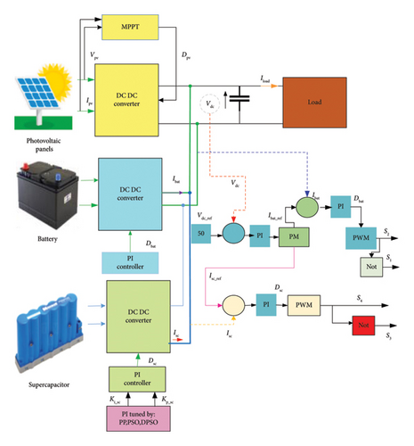
The batteries are used to store the exess of PV power for later use when needed. In addition, SC are used because of their ability to absorb and deliver power quickly. An PM algorithm determines the reference currents for either the battery or the SC. The battery’s reference currents are regulated using a PI controller. In contrast, the SC reference currents are determined from a PI control loop whose parameters KP_SC and Ki_SC are optimized based on PP, PSO, and DPSO algorithms.
2.1. PV Array Model
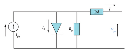
The PV cell model used in this study is depicted in Figure 2. For a more detailed understanding of the modeling of this solar cell, please refer to [35, 36].
2.2. HESS
The HESS incorporates two power sources: a Li battery and an SC.
2.2.1. Battery
The Li-ion battery works by using a chemical process to transform electrical energy. Li ions are reversibly exchanged between a positive and negative electrode during cycles of charge and discharge in this process. Despite having a comparatively low power density, this battery type is renowned for its high energy density [37].
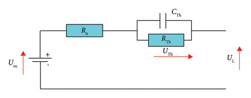
Figure 3 illustrates the equivalent electrical circuit model of a Li-ion battery [38]. This model includes several main components, open-circuit voltage UOC, resistors (R0 and RTh) representing ohmic resistance and polarization resistance, respectively, and capacitance (Cth) describing the battery’s transient response of the battery during charge and discharge.
A detailed description of the characteristics of this battery can be found in [38].
2.2.2. SC
SCs have a higher power density than batteries, making them more efficient and durable in terms of charge–discharge cycles [39].
Figure 4 illustrates the equivalent electrical circuit of the SC.
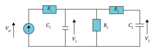
Here, C1 corresponds to the Helmholtz capacitance, C2 corresponds to the diffuse capacitance, R1 and RL represent the leakage resistances, and R2 represents the time-dependent resistance between the Helmholtz and diffuse capacitances. Further details on these parameter values can be found in [40, 41]
2.3. DC–DC Bidirectional Converter
The buck-boost converter for the battery is shown in Figure 5, while the converter for the SCs is shown in Figure 6. These converters serve to adjust the voltage level according to the system requirements [42].
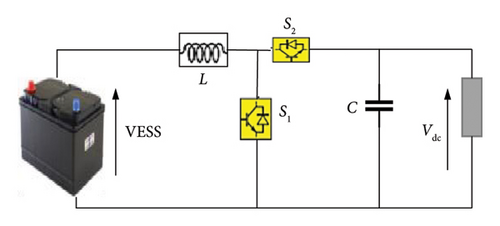
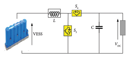
PV systems connect to the high-voltage DC bus through a bidirectional converter, this allows the load power supply to be controlled to meet the required power demand [43, 44].
The converter consists of the electrical energy storage voltage (EESV), an inductor L, a capacitor C, and switches (S1, S2) for the battery, and S3, S4 for the SC. The values of these parameters are described in detail in [44].
The bidirectional converter allows power transfer in both directions, allowing energy to flow from the load to the ESS and vice versa [45].
The buck-boost converter operates in two modes.
3. Energy Management for HESS
- •
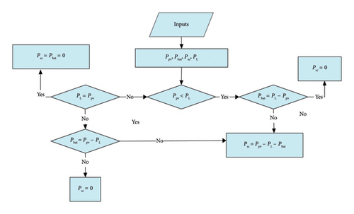
If (Ppv < PL), this indicates that the PV power is insufficient to meet the immediate load requirement, the State of Charge (SOC) of the SC starts to decrease (discharging mode) to quickly compensate for the peak of the transient power in this situation. This relieves the battery of the stress caused by these peaks and allows it to compensate for any steady drift between the supply and load powers.
- •
If (Ppv > PL), this indicates that the maximum PV power was accurately tracked, considering the irradiance surrounding the PV array. This implies that the PV system is capable of handling the load power. Consequently, SC begin to charge because batteries alone are insufficient for storing the excess of power for a short period. Although SC serve as secondary storage devices, they are crucial in ensuring the efficient and smooth operation of the PV–HESS under any operating conditions.
4. Control of HESS
Figure 8 illustrates the HESS control system. A PI controller regulates the DC bus. This controller calculates the reference current for the DC bus while ensuring that the DC link voltage (Vdc) remains at the desired level (Vdc_ref).
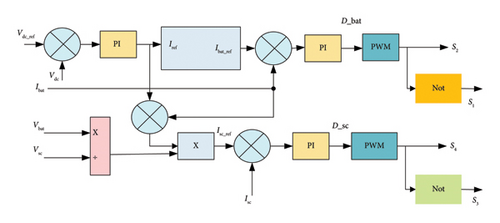
The EM system generates reference currents using two PI controllers. These controllers regulate the bidirectional converter that connects the batteries and the SC, allowing for charging and discharging. These reference currents are critical in keeping the DC bus voltage stable despite the fluctuating power of the PV and load.
The EM compares the nominal current of the battery (Ibat_n) with its reference current (Ibat_ref). If (Ibat_ref ≤ Ibat_n) is verified, in this case, the batteries charge energy. Otherwise, the transient part is received by the SC.
This condition aims to reduce the stress placed on the battery during charging/discharge cycles, increasing its life expectancy.
The actual battery current (Ibat) compared with (Ibat_ref).
The duty ratio (D) is generated by the PI controller and is used to control the switching operation of the battery converter. However, since the battery alone cannot meet the total power requirements [19], SC provides the additional remaining power.
As with batteries, the actual supercapacitor current (Isc) is compared with a reference value (Isc__ref), and the difference is used to generate the duty ratio for the PI controller. The PWM generator then uses this duty ratio to produce switching pulses for the SC converter [46].
5. Proposed Control Methods
In this work, the PI controller employed in the PV–HESS system was adjusted using three different approaches: PP, PSO, and DPSO, as described in the following sections.
5.1. PP Optimization Application to PI Controller Tuning
PP, also called full-state feedback, is a technique used to control various closed-loop parameters such as overshoot, peak time, rising time, and settling time [45, 47–49].
5.2. PI Controller Tuning Using PSO
In PSO, each individual strives to utilize information from other competitors to adjust their speed.
The particles are assumed to be randomly distributed across the search space and are characterized by their velocity and location. Each particle retains a memory of its ideal position. When the previous best position of all individual particles is considered, both the velocity and the movement are controlled.
As the swarm progresses, the particles move toward the optimal solution and converge toward the locations that are close to the global optimum.
However, the constraints of particle swarm have a low convergence rate in the iterative process with weak local search ability [53–55].
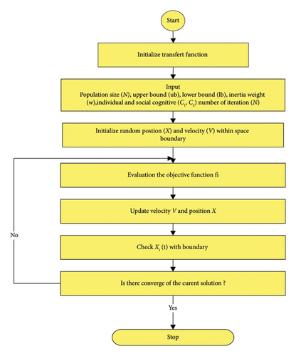
The flowchart of Figure 9 illustrates the PSO algorithm with the parameters depicted in Table A5. In this work, the PI controller parameters KP and TI were optimized using a PSO algorithm developed to attain optimal performance.
- 1.
Definition of PSO parameters:
- •
Number of variables (Var = 2).
- •
Population size (N);
- •
Upper bound (ub);
- •
Lower bound (lb);
- •
Inertia weight (w);
- •
Individual and social cognitive (c);
- •
Number of iterations (T).
- 2.
Selection of velocity and position
- a.
Velocity
() - b.
Position
() -
With: m = 1: Particles; n = 1: Var
- c.
Elite particle with equation (22)
() -
Where rand is a randomly generated number in the range [0, 1].
- 3.
The fitness function is used to determine and minimize the fitness value of each particle as follows:
() - 4.
Update both the global optimal solution and the individual optimal solution.
- 5.
Determine the parameters for the PI controller.
- 6.
If the overall ideal solution has been reached, stop iterating.
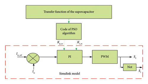
Figure 10 shows the connection between the proposed algorithm and the Simulink model. With reference to Figure 10, the input of the PI controller for a supercapacitor is the error between the actual current (Isc) and the reference current (Isc__ref) and the output is the duty cycle (D_sc) of the converter. However, this supercapacitor is defined by a transfer function that is a crucial element of the PSO metaheuristic algorithm’s code executed in MATLAB. The process of PSO begins with the initialization of the initial population of particles with initial positions and velocities. It evaluates the objective function at each particle location and determines the best function value and the best position to find the optimal gains of the regulator, and finally, this value is applied in the controller PI connected with SC.
5.3. PI Controller Tuning Using DPSO
The primary challenge with classic PSO is its susceptibility to getting trapped in local extreme domains. To overcome this limitation, this paper employs the DPSO [56], a modified version of the conventional PSO, which is known to enhance the optimization performance.
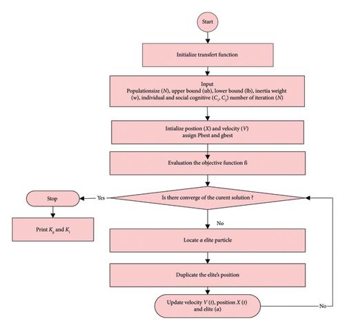
The algorithm starts with an ensemble, which is a collection of swarms that represent potential solutions to the optimization problem. These entities, called particles, navigate within the search area. The movement of the particles is guided by three equations, which represent the elite, velocity, and position in an iterative process.
The elite particle represents the best position of an individual randomly selected from the population. The flowchart of Figure 11 illustrates the DPSO algorithm.
As the swarming progresses, particles move toward the optimal solution, converging toward the global optimum [29].
- a.
Good at preventing early convergence, which improves its ability to deal with more complicated systems.
- b.
Convergence is reduced when computing is distributed.
- c.
Able to minimize the objective function better than PSO.
- d.
Can run continuously and adapt to changes in real time.
- 1.
Definition of DPSO parameters:
- •
Number of variables (Var = 2).
- •
Population size (N);
- •
Upper bound (ub);
- •
Lower bound (lb);
- •
Inertia weight (w);
- •
Individual and social cognitive (c);
- •
Number of iterations (T).
- 2.
- 3.
Define the previous best position (pbest), and the best fitness value (gbest).
- 4.
Define elite particle α(t)
() -
N denotes the maximum number of iterations.
-
Starting with the algorithm elite percentage α(t) = 50% and gradually reducing it to α(t) = 10%.
- 5.
Duplicate α(t).
- 6.
Update α(t), velocity and position.
- 7.
Any particle with a negative value or a value greater than the nominal controller gain value will be eliminated and replaced randomly in the search space.
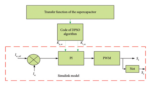
With reference to Figure 12, the input of the PI controller for a SC is the error between the actual current (Isc) and the reference current (Isc__ref) and the output is the duty cycle (D_sc) of the converter. However, this SC is characterized by a transfer function it is considered a basic part of the code of the new metaheuristic algorithm type DPSO is treated in MATLAB software which begins by creating the initial particles, and population and assigning them initial position and velocities. Also, it evaluates the objective function with the elite particle at each particle location and determines the best function value and the best position to find the optimal gains of the regulator, and finally, the values of DPSO as mentioned in Table A6 are applied in the controller PI connected with SC.
6. Sensitivity Analysis and Convergence of PSO and DPSO
This study aims to assess and compare the sensitivity and convergence of PSO and DPSO concerning different values of the parameters such as number of iterations, swarm size (N), inertia weight, and acceleration coefficients as described in the following.
6.1. Sensitivity Analysis Result: Swarm Size (N)
Tables 2 and 3 show the sensitivity analysis result with respect to swarm size (N) for PSO and DPSO algorithms. As expected, the results of Table 2 showed that PSO was most sensitive to the swarm size (N) with low convergence to the best particle, demonstrates the weak possibility of PSO particles finding the global minimum with a minimum value of function objective. Additionally, when different populations are expanded, DPSO performs more effectively and efficiently with a high convergence rate and is less sensitive than PSO, as shown in Table 3.
| N | Max of the objective function | Best of the objective function |
|---|---|---|
| 55 | 263.64 | 263.2 |
| 80 | 405.6845 | 405.6815 |
| 110 | 264 | 238 |
| N | Max of the objective function | Best of the objective function |
|---|---|---|
| 55 | 330 | 10 |
| 80 | 270 | 10 |
| 110 | 270 | 10 |
6.2. Sensitivity Analysis and Convergence Result—Maximum Number of Iterations
Tables 4 and 5 show the sensitivity analysis results for PSO and DPSO algorithms with respect to the maximum number of iterations equal to 1000. The maximum number of iterations substantially impacts the probability of the swarm approaching the global minimum. A small iteration would not provide particles enough time to explore the design space, whereas a high iteration would increase the computing load. This investigation examines the performance of PSO and DPSO with various iterations.
| Iteration | Max of the objective function | Best of the objective function |
|---|---|---|
| 10 | 270 | 218 |
| 50 | 270 | 218 |
| 100 | 270 | 200 |
| 200 | 270 | 200 |
| 300 | 270 | 200 |
| 400 | 270 | 200 |
| 500 | 270 | 200 |
| 600 | 270 | 200 |
| 700 | 270 | 200 |
| 800 | 270 | 200 |
| 900 | 270 | 200 |
| 1000 | 270 | 200 |
| Iteration | Max of the objective function | Best of the objective function |
|---|---|---|
| 10 | 272 | 200 |
| 50 | 272 | 200 |
| 100 | 272 | 200 |
| 200 | 272 | 200 |
| 300 | 272 | 10 |
| 400 | 272 | 10 |
| 500 | 272 | 10 |
| 600 | 272 | 10 |
| 700 | 272 | 10 |
| 800 | 272 | 10 |
| 900 | 272 | 10 |
| 1000 | 272 | 10 |
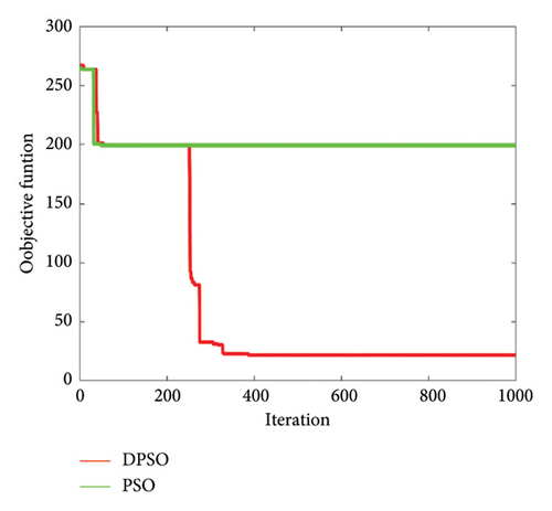
The maximum Iteration is contingent upon the type of optimization problem in hand. A high number of iterations increases the processing needs, whereas a low value reduces the likelihood of finding a global solution. The maximum iteration in this paper is varied in the interval [0, 1000]. The sensitivity analysis results are shown in the table. Increasing the number of iterations had an impact on the objective function of PSO and DPSO. It can be observed that between iterations 100 and 1000 similar statistical performance was achieved with PSO algorithm.
Figure 13 shows a comparison of the rate of convergence between PSO and DPSO, indicating and demonstrating the effectiveness of having a minimum value of function objective to describe the best particle and optimal gain of the PI controller as compared to PSO which failed to achieve the appropriate function and best global particle which indicates its weakness. Furthermore, Figure 13 illustrates the performance of these two algorithms in terms of accuracy and how close is the converged solution is to the global optimum. When the number of iterations increases, the accuracy of PSO decreases, which indicates that PSO is not always able to find the optimal solution at each iteration on a medium and large scale. It is seen that the DPSO algorithm is superior in terms of the objective function to reach the optimal solution with a value of 10. This value demonstrates that DPSO is more accurate than PSO.
6.2.1. Sensibility and Convergence With Inertia Weight (W)
The inertia weight improved particle search efficiency by balancing global and local searches. Table 6 presents the sensitivity analysis PSO algorithm with various inertia weights (W) of the swarm; it is observed that when the value of inertia weight increases, the objective function decreases with a lower value, which leads to the weakness in getting the optimal and best gains.
| W | Max of the objective function | Best of the objective function |
|---|---|---|
| 0.4 | 298 | 200 |
| 0.8 | 265 | 240 |
| 1.2 | 265.2 | 263.9 |
Although DPSO is not sensitive to the variation of inertia weight as shown in Table 7, it has the ability and effectiveness to reach the minimum value of the objective function leading to good convergence and good robustness of the algorithm.
| W | Max of the objective function | Best of the objective function |
|---|---|---|
| 0.4 | 270 | 10 |
| 0.8 | 270 | 10 |
| 1.2 | 270 | 10 |
6.2.2. Sensitivity Analysis and Convergence Result—Individual and Social Cognitive (c)
Changing the term (c) can cause particles to move to unwanted places. Therefore, the acceleration coefficient limitations are crucial in the implementation of the PSO algorithm. Table 8 shows the significant sensitivity of PSO with respect to the value of (c) and also the low converge rate of PSO with various individual and social cognitive (c) parameters, which demonstrates the lack of ability and weakness of the algorithm.
| W | Max of the objective function | Best of the objective function |
|---|---|---|
| 0.75 | 298 | 200 |
| 1.5 | 265 | 240 |
| 3.5 | 265.2 | 263.9 |
Table 9 illustrates the variation of individual and social cognitive value (c), and as expected, the DPSO is not sensitive to these variations and is able to reach the minimum and best value of the objective function.
| c | Max of the objective function | Best of the objective function |
|---|---|---|
| 0.75 | 265 | 240 |
| 1.5 | 265 | 219 |
| 3.5 | 265 | 219 |
7. Results and Discussion
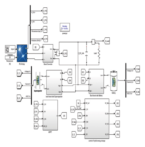
The overall system and its control scheme are implemented in MATLAB/Simulink and Sim Power Systems toolbox as depicted in Figure 14. The system parameters, including the gains of the PI controllers based on PP, PSO, and DPSO, are provided in the Appendix. Three simulation scenarios were considered to assess the performance of the proposed control scheme.
7.1. Scenario 1: Variable Solar Irradiance
This simulation was performed with a constant load of 500W. The irradiance is initially set at 0W/m2. It is then increased to 1000W/m2 from t = 0.4s and then reduced to 400W/m2 at t = 1.4s and maintained at this value until t = 2s.
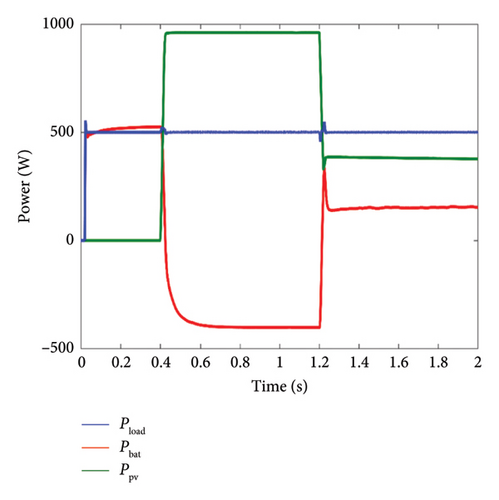
The power generated by the PV system is presented in Figure 15, which shows that the power produced by the PV system is directly linked to the solar irradiation profile, thus highlighting the significant impact of the irradiation level on the energy production of the PV system.
- •
From t = 0s to t = 0.4s, corresponding to an irradiation level of 0W/m2, the PV power is also 0W. In this case, as illustrated in Figure 15, the battery responds immediately by providing the power required by the load, ensuring the stability of the energy system.
- •
From t = 0.4s to t = 1.2s, as the irradiation reaches its nominal value of 1000W/m2, the PV system produces power equal to its nominal capacity. Consequently, the PV system fully satisfies the load’s power demand and any surplus of power will be stored in the battery.
- •
From t = 1.2s to t = 2s, the power generated by the PV system is lower than the load power requirement, and this depends on the level of irradiation. To maintain continuous energy supply and meet the load’s power demand, the battery promptly compensates for the power deficit of the PV system.
To enhance the battery’s lifespan, an SC is employed in combination with the battery. This step helps to reduce the stress on the battery by compensating for any delays in its charging or discharging process. Figure 16 shows the SC power profile under variable solar irradiance, which is controlled by a PI controller optimized using three different methods, namely, PP, PSO, and DPSO.
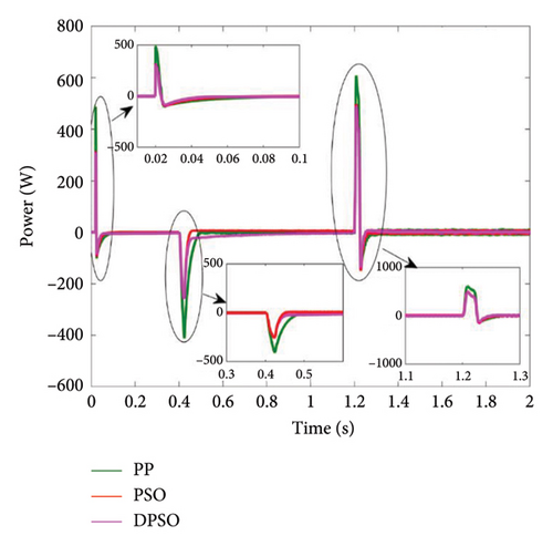
After analyzing the three scenarios discussed in the previous section, which examine the battery’s SOC and discharge concerning the power generated by the PV system and the power required by the load, it is clear that the SC system plays a vital role during the transient state. This refers to the period during which the battery is storing or releasing energy. The SC system has a faster response time compared with the battery. Among the different approaches, the DPSO approach stands out for its superior response time compared with PP and PSO. These findings contribute to ensuring that the battery operates effectively during transient conditions while minimizing its stress.
7.2. Scenario 2: Variable Load
In this scenario, it is assumed that the PV system operates at a constant irradiance level of 1000W/m2.
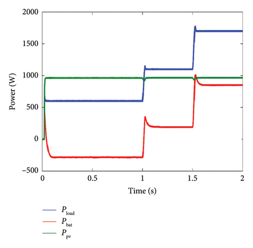
Figure 17 illustrates the profiles of the power generated by the PV system, the variations in the charging power requirements, as well as the evolution of the energy stored in the battery. It is clearly observable that the power produced by the PV system remains relatively constant.
- •
Between t = 0s and t = 1s, the power generated by the PV system exceeds the load demand. The excess power is sent to the battery during this period, thereby maintaining the balance.
- •
From t = 1s to t = 1.5s, the power generated by the PV system is not enough to meet the load power requirement. To maintain a stable energy supply and fulfill the demand of the load, the battery promptly compensates for the power deficit of the PV system.
- •
Between t = 1.5s and t = 2s, the power generated by the PV system consistently remains below the load power requirement. Consequently, the battery supplies power to the load, ensuring a stable energy balance between the power generation of the PV system and the power consumption of the load.
A comparison of the SC with the three different approaches, namely, PP, PSO, and DPSO, is shown in Figure 18. This shows that SC plays an important role during the transitional phase, especially when the battery starts discharging. It is worth noting that the DPSO approach outperforms the PI with the PP and PSO methods in terms of performance.
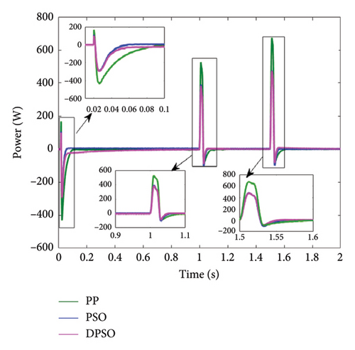
For a more thorough stability analysis, we compared the performance of the three proposed techniques in terms of transient response characteristics, namely, settling time, undershoot and overshoot, and rise time, under fluctuating load conditions.
7.3. Scenario 3: Evaluation of the SOC Consumption Under Different Temperatures
To comprehensively assess the efficiency and reliability of the PV_HESS, we have examined the impact changing weather conditions, specifically varying temperatures.
Figures 19 and 20 present the battery SOC with PP, PSO, and DPSO controllers under two different temperature scenarios, respectively. A comparative analysis was conducted through simulations spanning 2 s to evaluate the system’s performance.

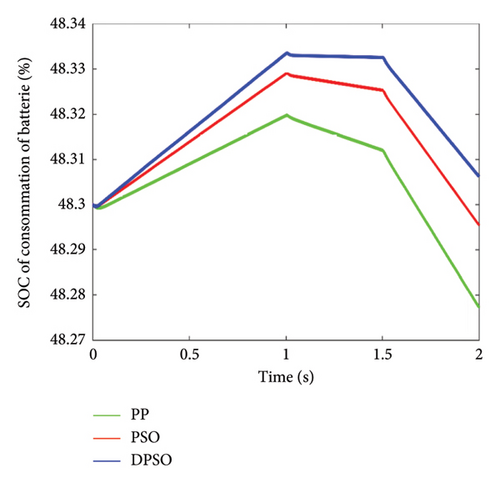
The results confirm that the PI controller fine-tuned by DPSO exhibits more efficient SOC utilization of batteries under diverse operating temperatures (0, 20) when compared with its PSO and PP.
This thorough investigation into the battery SOC usage at varying temperatures demonstrates the superior effectiveness of the DPSO-tuned PI controller, establishing its prowess in optimizing battery performance across a spectrum of environmental conditions.
The results show that integrating a supercapacitor with a battery reduced battery SOC fluctuations by minimizing peak currents and extending the battery life and performance.
7.4. Statistical Analysis of the PP-, PSO-, and DPSO-Optimized PI Controllers
After analyzing the results obtained, a comparative study of the performances of the algorithms used to select the best, as indicated in Table 10.
| PI | Rise time | Peak overshoot in (%) | Settling time in (ms) |
|---|---|---|---|
| Pole Placement | 1.85 × 10⁻⁴ | 37.3 | 2.35 |
| PSO | 4.1 × 10⁻⁴ | 8.45 | 2.29 |
| DPSO | 5.013 × 10⁻⁴ | 8.02 | 2.10 |
These results highlight that all PI controller designs based on heuristic methods exhibited zero steady-state error. In contrast, the DPSO tuning method demonstrated superior performance by significantly reducing the peak overshoot and settling time.
7.5. Robustness Tests of the PP-, PSO-, and DPSO-Optimized PI Controllers
In this section, the robustness of the algorithms is assessed under 30% and 60% abrupt changes in the load. The results obtained are summarized in Table 11. It has been observed that the DPSO algorithm was able to maintain stability of the system in the face of this variation, unlike PP and PSO algorithms.
| Tunnig approaches | 30% | 60% |
|---|---|---|
| Pole Placement | Unstable | Unstable |
| PSO | Stable | Unstable |
| DPSO | Sable | Stable |
8. Conclusion
This paper presents various optimization techniques including classical PP, PSO, and DPSO for tuning the gains of the PI controller of the SC current. The performance of these controllers is evaluated under different solar irradiation and load conditions. Several simulation scenarios are presented to analyze the system response. The results indicate that the DPSO-based PI control technique demonstrates superior performance in terms of settling time, overshoot, and rise-time accuracy with no sensitivity for the PI controller gains and with fast response to unexpected disturbances such as load variation, solar irradiation, and changes in the temperature, thus enhancing the dynamic response of the SC and reducing battery stress, resulting in a longer lifespan for HESS. This study possesses limitations, indicating potential areas for additional exploration, such as adaptive methodologies, whereby hybrid algorithms may provide the requisite dynamic response and improve the lifespan of the storage devices. These advancements might increase DPSO efficiency, scalability, and application in a variety of sectors, from real-time control systems to machine learning, thus proposing validation of the present research findings by comparison with results obtained from virtual simulations with experimental results in real time.
Conflicts of Interest
The authors declare no conflicts of interest.
Author Contributions
Samira Heroual conceived the main idea of the research, developed the study objectives, and formulated the hypotheses.
Belkacem Belabbas contributed significantly to the writing of the manuscript, providing important corrections, as well as detailed analyses and in-depth discussions on the results obtained.
Yasser Diab played a key role in enriching the text, particularly in the sections relating to results and interpretation of data. He also took charge of the submission of the manuscript and the management of exchanges with the editor.
Mohamed Metwally Mahmoud ensured the final editing of the text, ensuring its coherence and overall fluidity.
Tayeb Allaoui supervised the development of the study, ensuring that it was carried out by the objectives set.
Naima Benabdallah supervised the editing and improvement of figures and tables, ensuring their clarity and relevance within the article.
Funding
The authors wish to express their sincere gratitude to the Ministry of Higher Education and Scientific Research of Algeria for its indispensable financial support in completing this study. This work would not have been possible without the valuable assistance of the L2GEGI laboratory at the University of Tiaret, Algeria, to which the authors also extend their thanks. In addition, they would like to express their deep gratitude to the Nantes University, France, whose financial support was crucial for the successful completion of this research. The authors warmly thank this institution for its trust and unwavering commitment to scientific research.
Acknowledgments
The authors would like to express their deep gratitude to the University of Tiaret, Algeria, for its valuable support. They would also like to thank the Researcher Support Project of the University of Nantes, for their essential contribution to the completion of this work.
Appendix A: Parameters of the Studied System
| PPV | W | 120.7 |
| Voc,n | V | 21 |
| Isc,n | A | 8 |
| Imp | A | 7.1 |
| Rp | Ω | 31.6334 |
| Rs | Ω | 0.196 |
| KV | V/K | −0.358 |
| KI | A/K | 0.052 |
| Ns | — | 72 |
| Pn | W | 780 |
| In | A | 32.5 |
| Vn | V | 24 |
| C | Ah | 14 |
| soc | % | 50 |
| R | Ω | 12.6609 |
| Pn | W | 640 |
| In | A | 20 |
| Vn | V | 32 |
| Vi | V | 32 |
| C | F | 29 |
| Ns | — | 1.1 |
| Np | — | 1.1 |
| C | (Celsius) | 25 |
| C | F | 300.10−6 |
| P | W | 500 |
| Vdc | V | 50 |
| W | / | 0.7 |
| Var | / | 2 |
| Particles | / | 20 |
| c | / | 2 |
| Iteration | / | 100 |
| PI | KP_SC | KI_SC |
|---|---|---|
| Pole Placement | 0.53 | 2098 |
| PSO | 3.2563 | 1.6749 |
| DPSO | 0.0203 | 2.3104 |
Open Research
Data Availability Statement
The data that support the findings of this study are available from the corresponding author upon reasonable request.


