Distributed Hierarchical Controller Resilience Analysis in Islanded Microgrid Under Cyber-Attacks
Abstract
In islanded microgrid configurations, synchronization of distributed generators (DGs) becomes imperative. Achieving synchronization and control necessitates the establishment of communication links. However, communication channels are susceptible to various challenges, with cyber-attacks emerging as a primary concern. This paper examines the vulnerability of cooperative hierarchical controllers in the face of diverse cyber-attacks, including DoS, sensor and actuator attacks, and hijacking attacks. DGs are considered a multiagent system for stabilization and global synchronization of the network. Cyber-attacks on the secondary controller have been formalized, and an appropriate controller is designed for system synchronization and stability. The appropriate Lyapunov function is introduced to prove the stability. Then, the simultaneous stabilization and global synchronization conditions have been investigated by proving suitable theorems. A comprehensive case study is executed via simulation in MATLAB/Simulink, incorporating cyber-attack scenarios. The effects of cyber-attacks on this controller are eliminated, and the DGs are synchronized. For comparison, the resilience indicator has been used. In this controller, the cyber-attacks of the sensor and hijacking attack are well controlled. A DoS cyber-attack is more effective than other attacks and causes some DGs to go off the network. Also, comparing this controller to other controllers shows its greater resilience.
1. Introduction
The depletion of fossil fuel resources, adverse environmental impacts, and the inefficiency of traditional power grids have precipitated numerous challenges in the domain of power distribution. The adoption of microgrids and distributed generators (DGs) has emerged as a viable solution to address these issues.
The principal parameters governing microgrid control encompass frequency, voltage, and active and reactive power of DGs. Microgrids can operate in two modes: grid-connected and islanded modes. In the MG island mode, the controller must equalize the frequency and voltage of all DGs. In general, they should be equal to the slack output. Consequently, the production of all DGs must be adjusted and synchronized [1].
- I.
Centralized control.
- II.
Decentralized control.
- III.
Distributed control.
Centralized control entails the utilization of a centralized controller, where the output of all DGs is conveyed to a central controller. The centralized controller is integrated. This controller requires a communication channel; however, since it does not compare with neighboring outputs, it is not suitable for synchronization.
In decentralized control, each DG is equipped with an independent controller that operates autonomously without relying on neighboring DG information or requiring communication links. In this controller, synchronization remains an issue.
Distributed controllers, on the other hand, control each DG individually but utilize information from adjacent DGs. Consequently, communication links are imperative for synchronization and stabilization. Thus, communication networks play a crucial role in facilitating the exchange of information among neighboring DGs. The distributed method uses the information of neighboring agents. Hence, it is more suitable for synchronization and stabilization than other controllers, thus finding widespread application in microgrid control [2–4].
In the centralized and distributed controller, communication links are required for control. However, the utilization of communication links poses various challenges, including disruption, loss, uncertainty, noise, time delay, and susceptibility to cyber-attacks.
In this study, we employ a cooperative hierarchical distributed controller. This controller performs control in three primary, secondary, and tertiary layers. The tertiary layer determines the reference of the secondary layer. Also, the secondary layer refers to the primary layer [5, 6]. Reference [4] has provided complete explanations about the types of microgrid stability methods.
In recent studies [7], researchers have investigated the challenges posed by communication links in secondary controller communication and explored the effects of delay in hierarchical distributed controllers. Additionally, event-triggered methods in hierarchical controllers have been proposed to minimize data transmission [8, 9].
These disturbances disrupt the regulation and equalization of the output voltage and frequency. Consequently, numerous studies have been conducted in recent years to examine the effects of cyber-attacks on microgrids. Cyber-attacks exploit sensor output transmission and actuator output, with various attack methodologies targeting sensor output transmission channels for sabotage [10]. The literature extensively discusses communication channel issues and cyber-attacks on microgrids [11–14]. In [15], FDI attacks are considered from the perspective of multiagent systems. In [16, 17], cyber-attacks on sensors and actuators in multiagent systems are discussed. In [18], the secure control for T-S fuzzy systems under stealthy attacks is investigated, and a novel adaptive attack controller is studied. In [19], the stability effects of DoS, stealth, and deception attacks on the system are analyzed.
In [20, 21], the effect of Denial of Service (DoS) attacks on a hierarchical controller is investigated using the consensus method for the microgrid. In [22, 23], researchers study the cyber-attack stability problems of secondary controlled microgrids under DoS attacks. In [24], the attack effect of the sensor and actuator is involved in the microgrid equations, and the error effect is controlled using a H∞ robust control method. In [25], the data loss between the microgrid and the main grid is addressed. The error identification is discussed in [26, 27]. An adaptive resilience controller was designed in [28] to mitigate DoS and FDI cyber-attacks in a DC microgrid. Reference [29] addresses the simultaneous effects of two cyber-attacks on the microgrid by designing a suitable controller, with experimental results demonstrating efficacy.
Furthermore [14] investigates the effects of data loss and delay in microgrids, while [20] considers DoS cyber-attacks in the context of time delays. Reference [30] employs a decentralized controller from a multiagent systems perspective to counter the impact of DoS attacks in microgrids, while [31] discusses sensor attacks, hijacking attacks, and DoS attacks on secondary controllers, albeit with limited analysis of their stability and coordination. Reference [32] examines the effect of DoS cyber-attacks on microgrids, focusing on frequency using the secondary controller, with voltage remaining unexplored. In [3], microgrids are characterized as cyber-physical systems (CPS), with the effects of two types of cyber-attacks on the secondary controller investigated. Resilient control against cyber-attacks on communication links is proposed in [11, 33], albeit without studying sensor attacks. Reference [34] proposes quantum communication to enhance cybersecurity in distributed microgrid control, while [35] suggests adaptive controllers to mitigate the effects of errors and FDI attacks. Reference [36] analyzes the cyber-attack of false data injection on secondary frequency controllers. Finally, [37] introduces a robust controller for frequency synchronization of islanded microgrids against FDI attacks, though voltage and active power control are not explored. References [38, 39] discuss the hijacking attack, but stabilization and synchronization have not been studied.
Various disturbances in the communication channel can disrupt microgrid operations, potentially leading to instability and desynchronization. Fading, electromagnetic interference, noise, delay, uncertainty, and cyber-attacks are among the phenomena that can impact communication channels. This article delves into the ramifications of cyber-attacks on these channels.
In recent research, extensive investigations have been conducted into system stability, robustness, flexibility, and coordination. However, synchronous investigation of communication links and sensor attacks remains unexplored. Cyber-attacks on microgrids have primarily focused on attack detection and outcomes, with stability and synchronization considerations often overlooked. Communication channel disturbances have the potential to induce microgrid instability and disrupt synchronization. Thus, system resilience against cyber-attacks warrants investigation, evaluation, and comparison, with a view to enhancing system stability and synchronization.
This paper comprehensively analyzes various cyber-attacks on hierarchical controllers in microgrids from a multiagent systems perspective, treating DGs as agents interconnected via communication links delineated by an adjacency matrix. The study also examines cyber-attacks on sensors and communication links, followed by an analysis of system stabilization and synchronization. The microgrid equations are scrutinized during attacks, with stability assessments conducted. Synchronization and stabilization conditions in the presence of attacks are derived, with the overarching goal of designing a controller resilient to diverse cyber-attacks. Additionally, the study investigates the impact of different cyber-attacks on cooperative distributed hierarchical controllers, with resilience indices (RI) computed to compare the resilience of different cyber-attacks on the distributed cooperative hierarchical controller.
- 1.
Presentation of a novel robust controller for reference-based cooperative hierarchical control, showcasing the adverse effects of cyber-attacks on communication links between DGs in island mode. Modeling and formulation of cyber-attacks (DoS attacks, sensor attacks, and data hijacking) within the DG model are proposed. To our knowledge, cyber-attack modeling for cooperative hierarchical secondary controllers is presented for the first time.
- 2.
According to the authors’ knowledge, it is the first time to analyze microgrid stability in the presence of various types of cyber-attacks in the communication channel. A new Lyapunov function is defined for stability analysis.
- 3.
Investigate and analyze the synchronization conditions, reduce the matching error, and determine the resilience and robustness of all DGs.
- 4.
We demonstrate the resilience of the cooperative distributed hierarchical controller against various cyber-attacks. Additionally, we compare its performance with other controllers.
The most important advantage of the designed controller is to provide convenient coordination and low calculations. Despite time delays, cyber-attacks, and errors, coordination and stability are maintained.
The remainder of this paper is organized as follows: Sections 2 delve into the DG system model and designing a distributed hierarchical cooperative controller, respectively. Section 3 explores the Lemmas, Assumptions, and Definitions, while Section 4 examines cyber-attacks on such controllers. Section 5 discusses system stability and synchronization, followed by simulations in Section 6. Finally, Section 7 concludes the paper.
2. Large-Signal Dynamical and Control
Remark 1. The parameters of the microgrid model are fixed and known. Therefore, DGs can be considered model-based. In this model, various parts such as distributed sources, measuring devices, general power grid, control devices and telecommunication networks, power parts, voltage and current controllers, disparate filters, and loads are modeled [41–43].
2.1. Designing a Distributed Hierarchical Cooperative Controller
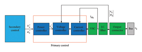
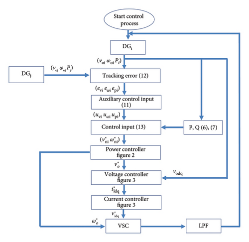
A cooperative distributed hierarchical controller consists of two main controllers: the primary controller and the secondary controller [2]. The secondary controller is for yaw reduction, and the primary controller is for stability. The general depiction of the DG and controller is illustrated in Figure 1. According to Figure 1, and should be reset by the secondary controller to minimize deviation in the input of the primary controller.
2.2. Primary Controller
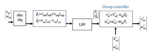
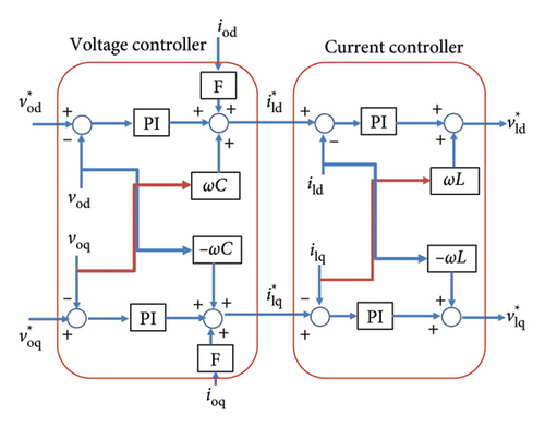
The primary controller offers a key advantage by implementing droop control, which inherently mitigates the risk of external interference. However, a notable drawback of droop control is the deviation of output values from the reference point. To address this issue, the secondary controller comes into play. The primary controller encompasses current, voltage, and power controllers, as illustrated in Figures 2 and 3. In specific references, the primary controller is conceptualized as the internal controller of the DG.
2.2.1. Calculation of Instantaneous and Average Power
2.2.2. Droop Controller
Then, based on Equation (8), the power controller output is computed. The and are subsequently fed into the voltage controller and the virtual synchronous converter (VSC), respectively. In this equation, nqi, mpi, , and represent the droop coefficients and reference values of the primary controller.
The primary voltage and current controllers, depicted in Figure 3, are implemented as proportional–integral (PI) controllers. The output of the voltage controller serves as the input to the current controller.
2.3. Secondary Controller
The secondary controller within the microgrid is illustrated in Figure 4. The output of the secondary controller and DGi output serve as inputs to the primary controller. The reference in the secondary controller is determined by the average voltage and frequency output or a consensus mechanism. The controller design employs the feedback linearization method.
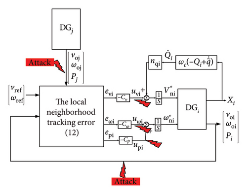
The main goal in designing this controller is to apply the appropriate control input to the primary controller to stabilize and synchronize the system and eliminate its deviation.
2.3.1. Using Feedback Linearization to Calculate the Appropriate Control Input
In Equation (11), evoi(t), eωoi(t), and ePoi(t) denote synchronization errors, while Cv, Cω, and CP represent voltage, frequency, and power control gains, respectively. uvi, uωi, and upi are auxiliary voltage, frequency, and power control inputs.
3. The Lemmas, Assumptions, and Definitions
3.1. Graph Theory
Communication channels serve as conduits for transferring data among DGs. This study delves into graph theory within the framework of multiagent systems to scrutinize DG communication channels, treating DGs as discrete entities analogous to agents. The assessment of communication channels is conducted utilizing an adjacency matrix.
- I.
Absence of incidence with neighbors
- II.
The members of the multiagent systems are coordinated with the rest of the group.
- III.
The cohesion of all members around a central focal point [45].
These principles are applicable to the analysis of DGs within the paradigm of multiagent systems. Reynold’s laws underscore the significance of cooperative dynamics among agents in accomplishing predefined objectives. Multiagent systems exhibit augmented performance, bolstering system compatibility and stability. Moreover, they showcase heightened resilience and efficacy in mitigating errors and combatting cyber-attacks [46, 47].
- 1.
Actuator errors stemming from diminished actuator efficiency.
- 2.
Sensor errors arise when sensors fail to measure outputs accurately.
- 3.
Communication link errors occur due to data transmission discrepancies.
The communication graph in graph theory is represented as G(v, ε, A), where AG ⊂ R × R is the set of nodes or DGs. V(G) = {v1, v2, …, vN} and E(G) ⊂ V(G) × V(G) are nodes or DGs, and communication links, respectively. (vi, vj) indicates that there is a communication link from node i to j.
Remark 2. In multiagent systems, stability and synchronization are pivotal. Synchronization in multiagent systems signifies that all agents attain a state of equilibrium, as delineated by Reynold’s second law. This principle is encapsulated by the formula:
In Equation (17), is the average value of system outputs [45, 49].
3.2. RI
Resilience is a critical parameter that emphasizes a system’s ability to withstand disruptions, showcasing its resistance to disturbances. In contrast, reliability gauges the performance of a power system in the face of various events, highlighting its robustness against extreme circumstances and susceptibility to vulnerabilities [50].
The degree of resilience spans from zero to infinity, where complete resilience signifies imperviousness to severe disruptions, rendering them inconsequential. Conversely, a resilience value of zero indicates system instability following any disturbance. Resilience ensures the continuity of electricity supply during significant disturbances while maintaining stability. A higher resilience coefficient signifies a diminished impact of disturbances on the system [51].
Defining resilience within the context of a power system lacks a universal definition. However, it generally encompasses the system’s capacity to recover from disruptions stemming from extreme events swiftly. System resilience is quantified based on its performance loss, with various methodologies available for performance assessment. Previous studies have delineated the loss of performance and its typologies [51].
In this study, resilience indicators are employed to probe the ramifications of cyber-attacks on the secondary controller. The assessment and comparison of cyber-attack impacts are evaluated utilizing this coefficient.
3.3. Assumptions and Lemma
The subsequent definitions and lemmas are imperative for the thorough investigation of this study.
Assumption 1.
- 1.
Cyber-Attacks on Physical Systems: It is assumed that cyber-attacks do not damage the physical systems of the microgrid but only make changes to the output information. The system reaches a steady state before the attack. The attacker has accurate information about the outputs and the system model and has access to the outputs. The attacker aims to remain undetectable; therefore, in sensor attacks and hijacking, the energy and attack scope is assumed to be limited.
- 2.
Denial of Service (DoS) Attacks: It is assumed that DoS attacks are typically executed in a short period and suddenly to quickly incapacitate the target system. DoS attacks are considered intermittent and occur at regular intervals.
- 3.
Data Injection and Sensor Network Disruption: It is assumed that the attacker injects false or misleading data into the sensor to deceive the system. Additionally, the attacker targets a network of sensors to disrupt communication between the sensors and the central system, but the configurations of the sensors remain unchanged.
- 4.
Hijacking Attack: In hijacking attacks, it is assumed that the attacker manipulates network routes to redirect data traffic to themselves. By stealing data, the attacker gains access to the microgrid’s outputs and replaces them with incorrect outputs.
Lemma 1. Assuming the microgrid tree is continuous and gi ≠ 0 for at least one of the root nodes. By defining δ as the vector representing discrepancies and errors in the format ofeo = (L + G)δ, the ensuing equation is derived:
Lemma 2. Considering the microgrid tree’s continuity and gi ≠ 0 for at least one of the root nodes. Consider matrix A = D + G = (D + G)T.
Q = (D + G)A + AT(D + G) is a positive definite matrix (D + G is a positive definite matrix) [53].
4. Cyber-Attacks on the Cooperative Distributed Hierarchical Controller
Given that the microgrid operates as a CPS, it is susceptible to cyber-attacks. Security concerns are discussed within three fundamental domains: confidentiality, integrity, and availability. Depending on the nature of the attack, one or more of these domains may be compromised.
- 1.
Deception attack
- 2.
DoS attack
- 3.
Reply attack [23].
Assuming represents the measured output, and y signifies the output received.
The figure illustrating the DGs and controllers with cyber-attacks is presented in Figure 4.
4.1. Sensor and Actuator Attacks in the Secondary Controller
In this attack, the wrong data amount is injected from the output of the sensors to the communication link. The difference between noise and sensor cyber-attacks is that the magnitude of cyber-attacks is much greater than the noise. In many cases, there are many similarities between a cyber-attack and a sensor fault. The main difference is that the cyber-attack enters the communication link, but the error is added to the sensor output [55].
In the hierarchical controller, a sensor attack occurs between the sensors of the secondary controllers, and an actuator attack occurs between the primary and secondary controllers. The sensor and actuator cyber-attacks cause the voltage and frequency information of a DG to reach the wrong neighboring DG and may cause system instability.
4.1.1. Mathematical Model of Sensory and Actuator Attack
The effect of this attack on the secondary controller using formulas (12)–(14) is as follows.
4.1.2. Voltage Controller With the Presence Sensor and Actuator Attacks
4.1.3. Frequency Controller With the Presence Sensor and Actuator Attacks
In the event of an attack, the variable is assigned a value of 1. Conversely, if there is no attack, is set to 0.
4.2. Hijacking Attacks in the Secondary Controller
In hijacking attacks, the system output is first removed. Then, it is replaced by the attacker with a value that is the same as the original output value.
4.2.1. Mathematical Model of Hijacking Attacks
If Η = 0, the attack has not happened, and if Η = 1, a cyber-attack has occurred in the communication network. In (31), yc(t), y(t), ya(t) is the damaged, nonattack, and attack output, respectively [38].
4.2.2. Voltage Controller With the Presence of Hijacking Attacks
4.2.3. Frequency Controller With the Presence of Hijacking Attacks
4.3. DoS Attacks in the Secondary Controller
In the DoS method, the attacker endeavors to sever the communication channel by obstructing data transmission, leading to information loss [56]. These attacks result in communication system disruptions, where hijacking and sensor attacks compromise measured values, communication links, or actuator values. The DoS attack, specifically, interrupts agent communication [57, 58].
4.3.1. Mathematical Model of DoS Attacks
4.3.2. Voltage and Frequency Controllers With the Presence of DoS Attacks
This study accounts for DoS attacks on sensors ().
5. Stability Analysis
The theories and lemmas presented herein are employed to validate the stability and coordination of the microgrid. Further elucidation of Lemmas 1 and 2, pertaining to synchronization and stabilization, is provided in [52, 53].
Theorem 1. Suppose the microgrid tree is continuous and gi ≠ 0 for at least one of the root nodes. If the secondary control input is perturbed by cyber-attacks in the form of , then the error error in becomes asymptotic stable. Additionally, the DG outputs synchronize with vref and all values converge to the same.
In Equation (49), is the error induced by the attack.
Proof 1. The general vector is defined as .
To prove synchronization, we need to demonstrate that the steady-state error tends to 0 despite this controller (i.e., limt⟶∞ ec⟶0). By considering Lemma 1, asymptotic stability is achieved, and synchronization is attained. According to the results, the system is globally coordinated. Also, the larger the Cv value, the faster the synchronization. Therefore, with the correct selection Cv, this controller is accomplished.
With the above proof, if the tree is connected, stability is maintained despite cyber-attacks. Additionally, as a multifunctional system, the voltage and frequency of all DGs should converge to the same value.
6. Case Studies
The presented content is validated through case studies. A case study model incorporating communication links is outlined in [44]. Furthermore, the model parameters are described, with the reference voltage set at 380 volts and the frequency at 50 Hz (ωref = 2πfref). Additionally, the secondary layer factors are CP = Cω = Cv = 50. DGs are interconnected via power and communication links. Various cyber-attacks’ effects on the secondary controller are evaluated using MATLAB simulations.
6.1. Scenario 1: Effect of Secondary Controller on Synchronization
The performance of the secondary and primary controllers of the system is examined in the absence of disturbances. Controllers are designed to enhance the flexibility, reliability, and performance of the microgrid in both grid-connected and islanded modes. In islanded microgrids, different controllers are commonly employed for power sharing. It is imperative to maintain constant frequency and voltage in island mode. Using only the primary controller results in a sharp voltage drop, disrupting synchronization, and causing frequency and voltage deviations. Consequently, minimizing deviations becomes necessary. Moreover, the system is sensitive to noise, disturbances, and unmodeled dynamics. While the primary controller ensures stability to a large extent, it may not adequately achieve synchronization. Thus, the secondary controller is introduced.
In steady-state operation, the frequency and voltage cannot vary significantly. Voltage may fluctuate by several volts, and the frequency by 1 Hz. While the system may withstand attacks momentarily, long-term effects are severe. Therefore, the designed controller must be robust and resilient against attacks.
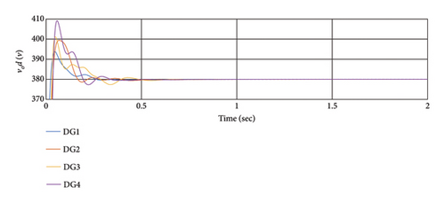
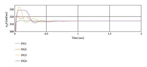
Figure 6 illustrates the efficiency of the secondary and primary controllers for synchronization without cyber-attacks. As depicted, this controller effectively synchronizes the frequency and voltage output, aligning it with the reference values. Moreover, the voltage and frequency ranges with this controller remain within permissible limits. The synchronization time is also deemed appropriate in this scenario.
6.2. Scenario 2: Sensor Attack on DG2 and DG3
Different DG positions were assessed to investigate the effects of the attack. In this scenario, the voltage sensor of DG2 and DG3 is attacked at t = 0.5 s, followed by the frequency sensor of DG2 and DG3 at t = 1 s. and finally, the active power sensor of DG2 and DG3 at t = 1.5 s. Voltage and power sensor attacks induce 10% changes in the output, while frequency sensor attacks result in 0.08% changes in the output. The impact on other DGs is analyzed. Figure 7 shows the effects of this attack. The simulation results demonstrate that when a cyber-attack occurs on the first DG, DG2 is most affected, followed by DG3 and DG4. Additionally, sensor cyber-attacks on neighboring DGs have a greater impact. Despite the cyber-attacks, the controller effectively mitigates their effects.
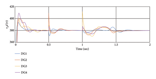
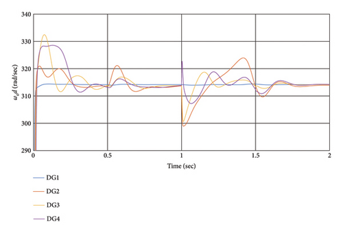
Moreover, a cyber-attack on the voltage sensor influences the frequency value, indicating an interaction between voltage and frequency controllers. For instance, at t = 0.5 s, the voltage sensor attack causes changes in frequency, with DG2 experiencing the maximum frequency effect. Changes in the power sensor output minimally affect system performance. The resilience coefficient in the presence of this attack is detailed in Table 1.
| DG1 | DG2 | DG3 | DG4 | |
|---|---|---|---|---|
| RI of voltage | 146 | 82 | 74 | 78 |
| RI of frequency | 2729 | 56 | 84 | 64 |
Despite the sensor attacks, all DGs achieve stability and synchronization. Notably, frequency variations are less than voltage variations, with maximum frequency changes of 6% while maintaining stability. The transient mode transition time is less than 0.2 s, indicating efficient performance. The system overload is tolerable, and synchronization is achieved promptly.
The value of the resilience coefficient in the presence of this attack is as follows:
6.3. Scenario 3: Hijacking Attack
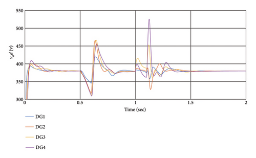
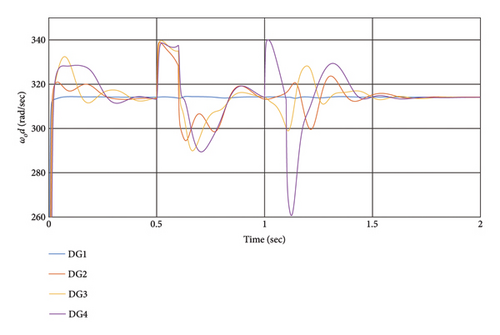
This section evaluates the impact of a hijacking attack on DGs. The hijacking attack occurs in the system from t = 0.5 s to t = .6 s with replacement voltage of and a frequency of between DG1 and DG2, also at t = 1 s to t = 1.1 s between DG3 and DG4. Notably, the replaced values cannot deviate significantly from the output value to avoid easy detection.
The simulation results depicted in Figure 8 demonstrate that disturbances in DG frequency induce changes in output voltage and vice versa. The impact of the attack on DGs depends on its location, with frequency attacks causing voltage changes and vice versa. Despite the cyber-attack, the distributed hierarchical controller effectively manages the outputs, achieving voltage and frequency synchronization in less than 0.5 s. Moreover, the secondary layer initiates synchronization after the attack concludes. Table 2 presents the RI in the presence of hijacking attacks. Following the end of the hijacking attack, the system swiftly returns to its normal state within 0.2 s. The extent of overshoot depends on the magnitude of the attack.
| DG1 | DG2 | DG3 | DG4 | |
|---|---|---|---|---|
| RI of voltage | 45 | 29 | 23 | 19 |
| RI of frequency | 1708 | 37 | 33 | 20 |
6.4. Scenario 4: Periodic DoS Cyber-Attack on the Communication Link Between DG1 and DG2
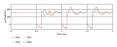
In this scenario, a periodic DoS attack occurs between DG1 and DG2, resulting in the loss of information reaching DG3 and DG4 during each attack. The attack parameters are defined as , , and τ0 = 0.5.
This scenario assesses the control method’s capability to withstand continuous connection and disconnection against a severe cyber-attack. The simulation results depicted in Figure 9 illustrate the effect of DoS cyber-attacks on the voltage (a) and frequency (b) of DGs between the DG1 and DG2 communication channels. During each attack, DG3 and DG4 are disconnected from the slack bus, resulting in outputs deviating from the reference. However, after the attacks conclude, it takes 0.4 s for all sources to recover their output values.
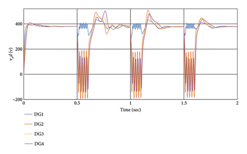
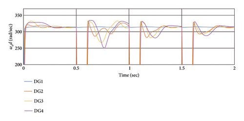
Despite the interruptions, the system performs well in dealing with this attack, with outputs restored and synchronized upon attack cessation.
When a DoS attack occurs, data loss during the attack may disrupt the stability and synchronization of a portion of the network. Disconnecting affected DGs from the network helps mitigate the problem. However, DGs closer to the attack source are more vulnerable. If a DG is disconnected from the root agent due to a DoS attack, it will be disconnected from the network. Nevertheless, if the tree remains connected, synchronization and stabilization can be maintained. Table 3 shows the RI in the presence of DoS attacks.
| DG1 | DG2 | DG3 | DG4 | |
|---|---|---|---|---|
| RI of voltage | 15 | 0.38 | 0.08 | 0.26 |
| RI of frequency | 612 | 0.19 | 0.19 | 0.21 |
Table 4 shows the peak voltage (PV) and frequency values (PF) due to various cyber-attacks. According to the cyber-attack table, DoS has a significant impact on the maximum voltage. Additionally, during the attack, the effect of kidnapping is high. If the connection to the root is disconnected, the maximum voltage value increases.
| DG1 | DG2 | DG3 | DG4 | ||
|---|---|---|---|---|---|
| No cyber attack | P.V. | 394 | 399 | 401 | 409 |
| P.F. | 315 | 321 | 333 | 329 | |
| Sensor attack | P.V. | 386 | 385 | 412 | 387 |
| P.F. | 314 | 324 | 332 | 328 | |
| Hijacking attack | P.V. | 419 | 465 | 466 | 525 |
| P.F. | 314 | 337 | 338 | 340 | |
| DoS attack | P.V. | 430 | 490 | 466 | 503 |
| P.F. | 314 | 332 | 331 | 333 | |
6.5. Scenario 5: Comparing the Proposed Method With the Methods in [48, 58]
To compare the effects of different cyber-attacks on the controllers, similar attacks are considered. The simulation results have been conducted for the previous four scenarios with identical conditions for controllers [48, 58]. The results are depicted in Figures 10 and 11, and RI with the presence of cyber-attacks are examined in Table 4.
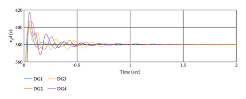
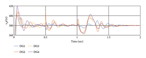
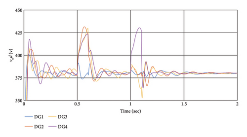
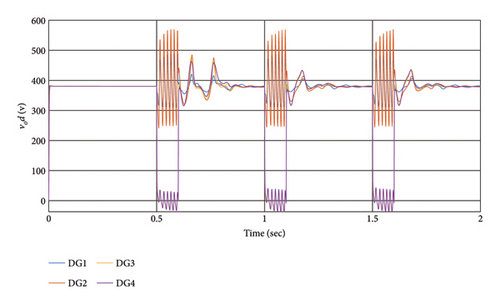
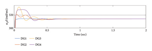
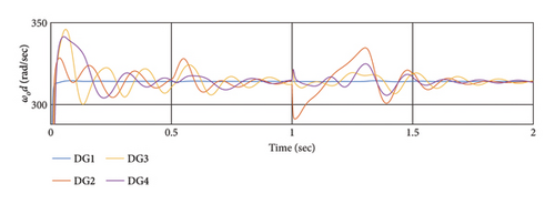
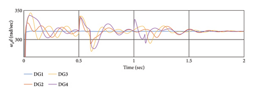
According to the simulation outcomes, both controllers achieve synchronization and stability for all DGs in a steady state, effectively mitigating the effects of cyber-attacks. However, the proposed method in this article demonstrates greater resilience to cyber-attacks compared to [48, 58]. Both controllers manage to synchronize all DGs after the attack, but the proposed method exhibits better resilience and faster synchronization. In conclusion, the proposed method outperforms [48, 58] in addressing cyber-attacks, achieving faster synchronization and demonstrating superior resilience, as evident from the simulation results and Table 5.
| DG1 | DG2 | DG3 | DG4 | ||
|---|---|---|---|---|---|
| Sensor attack | RI of voltage | 70 | 28 | 34 | 33 |
| RI of frequency | 1455 | 22 | 27 | 31 | |
| Hijacking attack | RI of voltage | 69 | 27 | 26 | 21 |
| RI of frequency | 1457 | 28 | 20 | 18 | |
| DoS cyber-attack | RI of voltage | 11 | 6 | 0.02 | 0.02 |
| RI of frequency | 844 | 0.04 | 0.02 | 0.04 | |
7. Conclusion
In conclusion, this paper addressed the critical issue of cyber-attacks on microgrids, emphasizing the significance of synchronization in islanded microgrids where communication channels play a crucial role. By modeling the microgrid as a multiagent system and utilizing graph theory, the impact of various cyber-attacks on microgrid communication channels was investigated. The cooperative distributed hierarchical controller was designed to manage and synchronize the system, considering three types of cyber-attacks: sensor and actuator attacks, hijacking attacks, and DoS attacks.
A novel Lyapunov function was proposed to analyze the effects of cyber-attacks on microgrid stability, and theorems were presented to prove synchronization even in the presence of cyber-attacks. Through simulation using Matlab/Simulink software, the effectiveness of the controller in mitigating the effects of cyber-attacks was demonstrated, with RI used to assess resilience against different attack scenarios.
The results showed that while all types of cyber-attacks pose challenges, the impact of DoS attacks was particularly severe, causing instability in DGs disconnected from the slack node. However, the controller was able to stabilize and synchronize the system after the DoS attacks ceased. Additionally, the controller effectively mitigated the effects of hijacking and sensor attacks, restoring synchronization and bringing frequency and voltage back to reference values.
The effects of cyber-attacks varied depending on the network adjacency matrix, with DGs disconnected from the reference node experiencing greater instability. The proposed controller implemented Reynold’s laws, emphasizing the cooperation and influence of neighboring DGs for stability and synchronization.
At the end of this study, the impact of cyber-attacks on different controllers and the proposed controller is shown. The RI are utilized to assess the flexibility of a controller in the face of cyber-attacks. Based on this metric, the controller we designed demonstrates superior resilience compared to other controllers. Specifically, our designed controller achieves a higher resilience index, indicating its enhanced capability to withstand and recover from cyber-attacks.
During the assessment of all controllers, it was observed that the resilience was notably low during DoS attacks, which led to system instability. Despite this, the designed controller effectively restored the system to a stable state postattack, highlighting its robustness and recovery capability.
The results show the better performance of the proposed controller.
- 1.
Further examination of communication channel issues such as interference, delay, noise, and fading.
- 2.
Investigation and comparison of cyber-attacks on various secondary controller architectures.
- 3.
Exploration of robust control methods to handle uncertain cyber-attacks and ensure system stability.
- 4.
Analysis of DoS attacks using switching control methods in microgrids.
Addressing these areas could enhance the understanding of cyber-attack resilience in microgrids and contribute to the development of more robust control strategies.
Nomenclature
-
- Pi
-
- Average active power
-
- Qi
-
- Average reactive power
-
-
- Instantaneous active power
-
-
- Instantaneous reactive power
-
- E(G)
-
- Communication link matrix
-
- A
-
- System matrix
-
- Ac
-
- State matrix with attack
-
-
- Secondary controller output voltage
-
-
- The angular frequency of secondary controller output
-
- Vref
-
- Reference voltage
-
- ωref
-
- Reference angular frequency
-
- ωc
-
- Low-pass filter cutoff frequency
-
- voi
-
- DGi output voltage
-
- ωoi
-
- DGi output angular frequency
-
- ioi
-
- DGi output current
-
- ωcom
-
- Angular frequency in the usual framework
-
-
- The output voltage of the attack
-
-
- The output frequency of the attack
-
-
- Power control gain
-
-
- The output frequency with attack
-
- uv
-
- Auxiliary voltage control input
-
- uω
-
- Auxiliary frequency control input
-
- uP
-
- Auxiliary active power control input
-
- uc
-
- Control input with attack
-
- ea
-
- Error signal caused by the attack
-
- aij
-
- Areas of the adjacency matrix
-
-
- Frequency droop coefficient
-
- x(t)
-
- System state matrix
-
- G
-
- DGs to slack connection matrix
-
- L
-
- The Laplacian matrix
-
- gi
-
- Pinning gain
-
- nqi
-
- Voltage droop coefficient
-
- δ
-
- The global disagreement vector
-
- Cω
-
- Angular frequency control gain
-
- Cv
-
- Voltage control gain
-
- CP
-
- Power control gain
-
- σ
-
- Singular value
-
- xc
-
- Parameter x disrupted by the attack
-
- xa
-
- System matrix with attack
-
- x∗(t)
-
- Average system outputs
-
- y
-
- Measured information
-
-
- Information received from sensor
-
- y∗(t)
-
- The average value of system outputs
-
- Y
-
- Past outputs
-
- E(G)
-
- Communication links matrix
-
- RI
-
- Resilience indices
-
- V(G)
-
- Nodes of multiagent system
-
- αi, βi
-
- Sensory cyber-attack coefficients
-
- Η
-
- Hijacking cyber-attack coefficients
-
- Δi
-
- DoS cyber-attack coefficients
-
-
- DoS attack duration
-
-
- The start time of the sth DoS attack
-
-
- The total duration of attacks
Conflicts of Interest
The authors declare no conflicts of interest.
Funding
This investigation is in the form of academic research and is not funded by any organization.
Open Research
Data Availability Statement
Data supporting the findings of this study are available from the corresponding author upon reasonable request.


