Novel Path Planning Algorithm for the Mobile Robot in Power Transformer Substation
Abstract
In response to the issue of low search efficiency caused by the large number of expanded nodes when mobile robots use traditional A∗ algorithm for path planning in complex environments, an improved A∗ algorithm based on four-way search has been proposed. This algorithm leverages Euclidean distance to weight the heuristic function on the basis of the traditional A∗ algorithm and reduces the number of expanded nodes and search time through the four-way search algorithm. Subsequently, experiments were conducted using maps to verify the performance of the improved algorithm. The experimental results indicate that the simulation of the improved A∗ algorithm based on four-way search can achieve higher search efficiency, with fewer expanded nodes, which is more conducive to the path planning of mobile robots.
1. Introduction
The power transformer substation contains a multitude of equipment distributed over a wide area. Currently, the methods of regular manual inspection and testing, as well as the deployment of fixed sensors for fault monitoring, are inefficient, costly, limited in flexibility, and labor-intensive, making it difficult to achieve large-scale real-time online inspection within the substation. The integration of multiple energy sources (such as electricity, natural gas, heat, and renewable energy) in regional energy systems has become a critical approach to achieving energy efficiency, sustainability, and resilience. However, the optimal dispatch of these diverse energy sources poses significant challenges due to their varying characteristics, interdependencies, and uncertainties [1, 2].
In response to these issues, there is an urgent need to develop a four-legged bionic robot with flexible operational capabilities to fill the technological gap in cross-domain operation and maintenance control of substation equipment.
Global path planning algorithms enable mobile robots to find a collision-free path from the initial state to the target state in a known environment [3]. Based on grid-based maps, common algorithms include Dijkstra, A∗, RRT, and ant colony optimization [4–9]. Among them, the A∗ algorithm is a heuristic search algorithm that can very effectively complete global path planning tasks, but it has issues such as a wide search range leading to low planning efficiency and high memory overhead.
In response to the issue, Guo and Yang [10] conducted an in-depth study on the neighborhood search of the A∗ algorithm, expanding the traditional eight-neighborhood search to a twenty-four neighborhood search, effectively addressing the low search efficiency of the A∗ algorithm. Chen [11] proposed a weighted evaluation function, increasing the proportion of the estimated cost in the evaluation function based on the traditional A∗ algorithm, thereby enhancing the search efficiency. Liu and colleagues [12] used a six-directional search neighborhood algorithm to conduct simulation experiments on three different grid maps, and the results showed that the search time and expanded nodes were significantly improved compared to the traditional A∗ algorithm, with more noticeable effects as the scale of the grid maps increased. Guo and colleagues [13] introduced a bidirectional alternating search strategy, filtering path points to reduce the difficulty of the search. Huang and others [14] have implemented robot obstacle avoidance by integrating the A∗ algorithm with the dynamic window approach. It reduced the turning points and path length, which could avoid falling into local optimal solutions. Xie [15] addressed issues such as insufficient expansion direction in the A∗ algorithm by improving the priority search strategy. The actual application research with ASR mobile robots verified that this method can enhance efficient path search in complex scale maps. Zeng and Zhang [16] and others combined the improved A∗ algorithm with the DWA algorithm, which reduced the number of traversed nodes by 59.9% and the number of turning points by 58.5%. However, there was not a significant shortening in the path length. Yang and others [17] proposed an improved A∗ path planning algorithm based on a dynamic distance field map, which solved the problems that the path planned by the A∗ algorithm was close to obstacles and had many turning points. By adding a maximum distance limit when calculating the distance field map, the problem of redundant planned paths in a large open environment was solved. Kun and others [18] proposed a path planning algorithm, DAVSA, which integrates an improved dynamic obstacle avoidance strategy and a variable step size A∗ algorithm. They screened out key jump points as extended nodes to be considered by the A∗ algorithm and quickly generated a global optimal path. Kuang et al. conducted corresponding research on obstacle avoidance of intelligent vehicles by combining the A∗ algorithm with the artificial potential field method [19].
In response to the performance of the A∗ algorithm being heavily dependent on the heuristic function, which can lead to getting stuck in local optimal solutions, and the inaccurate heuristic function causing nonoptimal paths, or frequent recalculation of paths leading to high search time costs, this paper improves the heuristic function of the traditional A∗ algorithm [20] to make the estimated cost closer to the actual cost and proposes a four-directional neighborhood search method to compensate for the path search, reducing the search cost.
2. The Improved A∗ Algorithm and Search Algorithm
This section may be divided by subheadings. It should provide a concise and precise description of the experimental results, their interpretation, and the experimental conclusions that can be drawn.
2.1. A∗ Path Planning Algorithm
2.1.1. Environment Modeling
-
Condition 1: Robot environment modeling is based on a planar diagram, disregarding the height information of obstacles.
-
Condition 2: In robot path planning, obstacles and the robot occupy an entire grid with each step, and the height of the robot is ignored.
-
Condition 3: The workspace is evenly divided into A∗B grids of equal area, with (i, j) representing the position information of each grid. The workspace information (Ω) is shown in the following equation:
()
That is, Nij is represented as 1 if the grid contains an obstacle; Nij is represented as 0 if the grid is free space.
2.1.2. A∗ Algorithm
The A∗ algorithm is a heuristic search path planning algorithm that combines the advantages of Dijkstra’s algorithm and breadth-first search (BFS). It uses a neighborhood search algorithm to expand eight neighboring points of a node, with the function of finding the globally optimal path from the initial point to the target point.
The common methods for calculating the actual cost g(n) and the estimated cost h(n) include Euclidean distance, Manhattan distance, and Chebyshev distance, as shown in Figure 1.
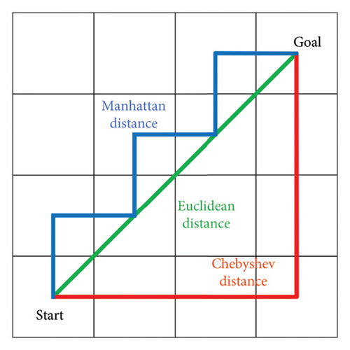
The A∗ algorithm utilizes different methods to calculate the actual cost g(n) and the estimated cost h(n). These methods are based on various distance metrics.
Euclidean distance: This is the straight-line distance between two points in a plane, calculated using the Pythagorean theorem. It is the most straightforward measure of distance but may not always be applicable in grid-based pathfinding where movement is restricted to certain directions.
Manhattan distance: Also known as taxicab or city block distance, this method calculates the distance by summing the absolute differences of their Cartesian coordinates. It is particularly useful in grid environments where movement is allowed only along the horizontal and vertical axes.
Chebyshev distance: This method calculates the maximum absolute difference between the coordinates of two points. In the context of a grid, it can be thought of as the maximum number of moves required to get from one point to another, where each move can be in any direction (horizontal, vertical, or diagonal).
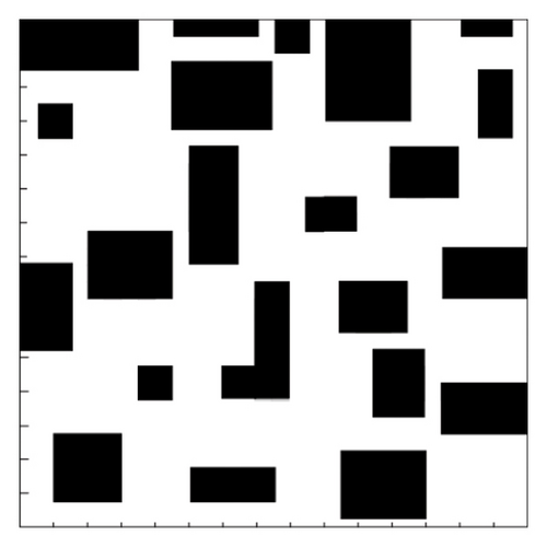
Figure 2 illustrates the comparison between these three distance metrics, showing how they would calculate the distance between two points on a grid. Each method has its own advantages and is chosen based on the specific constraints and requirements of the pathfinding problem at hand.
- 1.
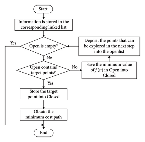
Create an OpenList and a CloseList, and put the starting point into the OpenList.
- 2.
Select the node with the minimum cost f(n) in the OpenList as the current node to be expanded and remove it.
- 3.
Move the current node to the CloseList and check if it is the goal point. If the current node is not the goal point, continue the loop.
- 4.
Search the neighborhood of the current node, exclude nodes in the CloseList and obstacle nodes, select other nodes that meet the conditions and store them in the OpenList, and then go back to Step 2 to continue execution.
In path planning, the A∗ algorithm places the searched nodes in two types of lists: the OpenList and the CloseList. The OpenList stores all passable points on the way from the starting point to the goal point, while the CloseList mainly stores the nodes with the minimum F value selected from the OpenList in each loop. The path search is conducted by switching between the two lists. The A∗ algorithm is shown in Figure 3.
2.2. Improved A∗ Algorithm
2.2.1. Adaptive Weighted Evaluation Function
The core of the A∗ algorithm is the setting of the evaluation function, and the heuristic function h(n) has a significant impact on this evaluation function. Different calculation methods for h(n) lead to different planning results. The influence of h(n) on the A∗ algorithm is as follows: When the current node is farther from the goal node, the search efficiency should be increased, i.e., the weight of h(n) in the evaluation function should be increased; when the current node is closer to the goal node, the precision of the algorithm should be increased, i.e., the weight of g(n) in the evaluation function should be increased.
In this context, k represents the variable weight coefficient for h(n) and g(n) in the evaluation function; L represents the distance between the current node and the goal node.
When the traditional A∗ algorithm deals with path planning, it usually does not consider the speed constraint conditions and defaults that the moving speed of each node is the same. In practical application scenarios, such as robot path planning and autonomous driving, this will result in an unrealistic planned path because the speed of actual moving objects is limited and the speed also varies in different terrains or environments.
The improved model introduces unified speed constraint conditions and fully considers the speed factor when calculating the path. It will determine the moving time and distance between each node according to the maximum speed, acceleration of the object, and its current motion state. For example, when encountering a narrow passage, the speed will be reduced to ensure safe passage; when in an open area and the distance to the target is far, the speed can be appropriately increased. In this way, the planned path not only satisfies the kinematic principles but also better meets the actual application requirements, improving the practicality and reliability of the path.
In the A∗ algorithm, the heuristic function can be designed to take into account velocity and acceleration constraints, guiding the search process toward paths that satisfy these dynamic constraints.
2.2.2. Improvement of Neighborhood Search Algorithm
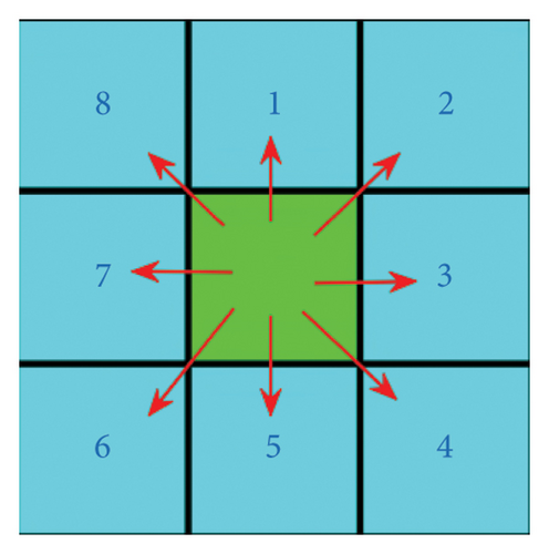
The traditional A∗ algorithm uses an eight-neighborhood search algorithm to expand the search for neighboring points, and based on the expansion search of two nodes, it finds the global shortest path. The eight-neighborhood search diagram is shown in Figure 4.
- 1.
Lack of clarity in purpose: The eight-neighborhood search may lack a clear goal orientation, leading to the repeated consideration and search of many nodes. This increases the number of nodes the A∗ algorithm needs to expand, thereby reducing the efficiency of the search.
- 2.
Limited search range: This search method is confined to only the 8 neighboring nodes around the current node, which narrows the search horizon and may not effectively explore broader areas.
- 3.
Redundant nodes and turning points: Due to the limitation of the search range, there may be too many redundant nodes and unnecessary turning points. This not only increases the computational load but also is detrimental to generating smooth paths.
- 4.
Not meeting automated guided vehicle (AGV) path requirements: For applications such as AGVs, the smoothness of the path is very important. The limitations of the eight-neighborhood search may not meet the requirements for path smoothness, resulting in paths that are not smooth enough.
To avoid situations where the path clings to obstacles in path planning, an algorithm that automatically switches neighborhood search strategies can be designed, as follows.
Eight-neighborhood search condition: When there are no obstacles in the eight neighborhoods around the node being expanded, or obstacles only exist on the diagonal directions of the current expanded node, the algorithm will use the eight-neighborhood search algorithm for path expansion.
- (i)
When there are no obstacles in the eight neighborhoods around the currently expanding node, or when obstacles only exist on the diagonal of the currently expanding node, the eight-neighborhood search algorithm is adopted.
- (ii)
When there is an obstacle in one of the four neighborhoods (up, down, left, and right) of the currently expanding node, the two diagonal neighborhoods adjacent to that neighborhood are regarded as impassable. As shown in Figure 5, if there is an obstacle in the right neighborhood of the currently expanding node, then the upper-right and lower-right neighborhoods are regarded as impassable, and the expandable nodes are the left, upper-left, lower-left, up, and down neighborhoods.
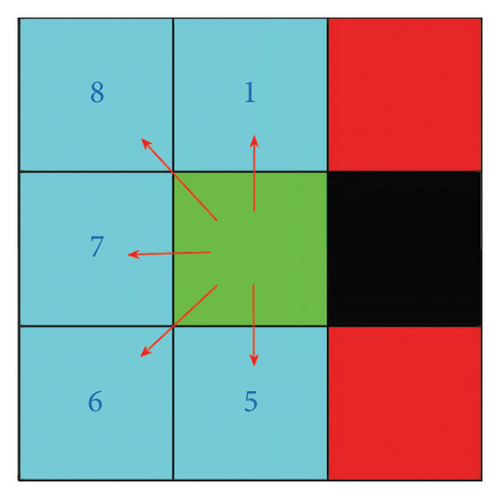
The principle of automatically switching the neighborhood search path is shown in Figure 2. It can be seen that, compared with the traditional eight-neighborhood search algorithm, this algorithm can effectively prevent the planned path from being close to obstacles. Results of the automatically switching neighborhood search path are shown in Figure 6.

2.2.3. Improvement of A∗ Algorithm
- 1.
Prioritize nodes closer to the goal: When there are multiple nodes in the OpenList with the same F value, i.e., they have the same minimum F value, the algorithm will select those nodes that are closer to the goal point, which are the nodes with the smallest heuristic cost h(n), as the next node to expand.
- 2.
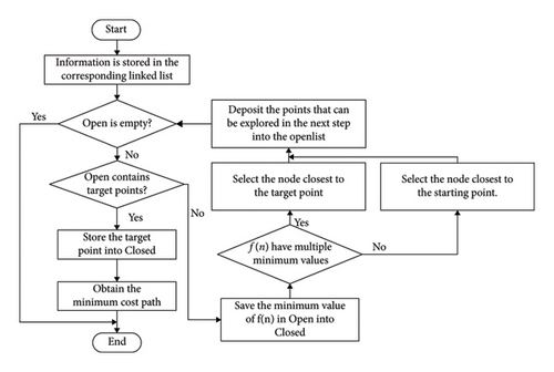
Secondary selection of nodes closer to the start point: If there are multiple nodes with the same h(n) value, meaning they are equally close to the goal point, then the algorithm will further select those nodes that are closer to the start point, which are the nodes with the smallest actual cost g(n), as the next node to expand. The flowchart of OpenList improvement is shown in Figure 7.
3. Case Studies
3.1. Mobile Robot
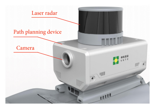
In order to verify the effectiveness of the improved path planning algorithm proposed in this paper, comprehensive case studies are carried out in this paper. Figure 8 illustrates the quadruped mobile robot used in the case study, which includes the path planning device, laser radar, and camera. The proposed novel path planning algorithm is utilized in the robot.

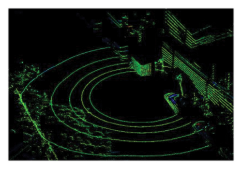
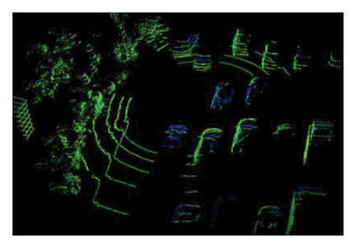
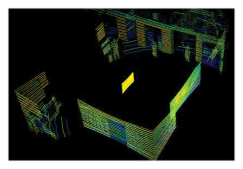
Besides, aiming to achieve the path planning algorithm, Figure 9 provides the laser radar’s space scanning result, which has the ability to obtain three-dimensional spatial information.
3.2. Comparative Experiment 1
Comparative Experiment 1: As shown in Figure 10, a comparative validation was conducted in a 30 × 30 simple grid map environment among the traditional A∗ algorithm, the improved H(n) algorithm, and the improved A∗ algorithm. The green star is the starting point, and the red star is the endpoint.
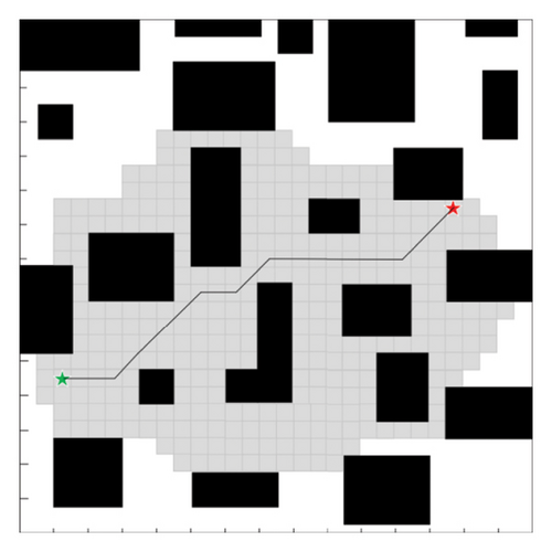
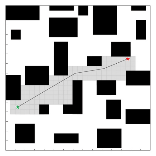
As can be seen in Figure 9 and Table 1, by analyzing the simulation of Comparative Experiment 1 results, it can be concluded that in a 30 × 30 grid map environment, due to the simplicity of the map, the improvements in path length and the number of turning points of the A∗ algorithm proposed in this paper are not significantly noticeable. However, compared to the traditional A∗ algorithm, the improved A∗ algorithm presented in this paper reduces the number of expanded nodes and search time by 65.74% and 34.11%, respectively.
| Comparison items | Traditional A∗ algorithm | Improved A∗ algorithm |
|---|---|---|
| Extension node | 317 | 208 |
| Time (s) | 7.33 | 4.83 |
| Length | 30.69 | 19.50 |
| Node number | 7 | 4 |
3.3. Comparative Experiment 2
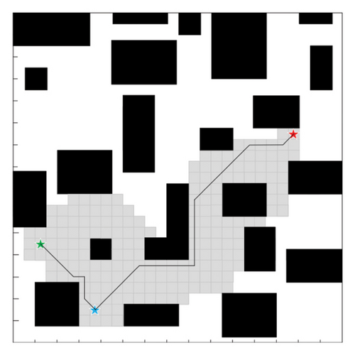
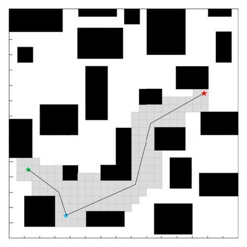
Comparative Experiment 2: Based on the control Experiment 1, a fixed node is added, and the blue star represents this node.
As can be seen in Figure 11 and Table 2, by analyzing the simulation of Comparative Experiment 2 results, compared to the traditional A∗ algorithm, the improved A∗ algorithm presented in this paper reduces the number of expanded nodes and search time by 26.63% and 29.45%, respectively.
| Comparison items | Traditional A∗ algorithm | Improved A∗ algorithm |
|---|---|---|
| Extension node | 184 | 135 |
| Time (s) | 9.54 | 6.73 |
| Length | 40.17 | 28.09 |
| Node number | 10 | 6 |
3.4. Comparative Experiment 3
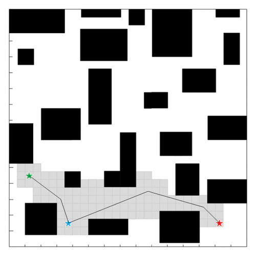
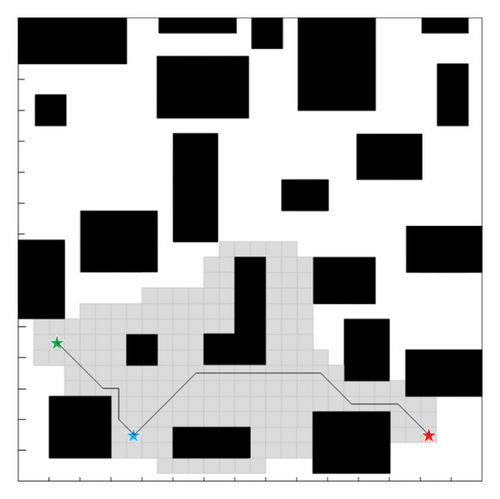
Comparative Experiment 3: Based on the control Experiment 1 and Experiment 2 to change the target point of the simulation experiment, a fixed node is added, and the blue star represents this node. Comparative Experiment 3 is shown in Figure 12 and Table 3.
| Comparison items | Traditional A∗ algorithm | Improved A∗ algorithm |
|---|---|---|
| Extension node | 179 | 111 |
| Time (s) | 6.58 | 5.15 |
| Length | 38.27 | 56.88 |
| Node number | 10 | 6 |
4. Discussion
To address the traditional A∗ algorithm’s shortcomings such as low search efficiency, this paper integrates heuristic function improvement strategies and four-directional search strategies on top of the traditional A∗ algorithm, proposing a new A∗ algorithm based on four-directional search. To validate the effectiveness of the proposed algorithm, a series of simulation experiments were conducted using a grid map, and the results indicate the following.
The improved A∗ algorithm proposed in this paper demonstrates significant improvements in search time and the number of expanded nodes compared to the traditional A∗ algorithm.
Conflicts of Interest
The authors declare no conflicts of interest.
Funding
This work was funded through the Technology Project of State Grid Ningxia Electric Power Co., Ltd. (Project Number: 5229CG240005).
Acknowledgments
This paper was supported by State Grid Ningxia Electric Power Co., Ltd., Technology Project (5229CG240005).
Open Research
Data Availability Statement
All data generated or analyzed during this study are included in this published article.


