Finite-Time Consensus Pinning Control Method for Multiple Inverters–Paralleled Photovoltaic Microgrid
Abstract
Multiple inverters–paralleled photovoltaic microgrid is a typical cyber-physical system with varying line impedances and unsynchronized nodes that result in unbalanced power sharing and are prone to cause circulating current. Therefore, a complex network based on a finite-time consensus pinning control method for microgrids is proposed in this paper. First, the distributed generators are regarded as agent nodes, and a small-world network model is established based on complex network theory. To overcome the subjectivity of relying on expert experience to select pinning nodes in previous pinning control methods, a selection algorithm that uses only nodes with large out-degree as pinning nodes is proposed to reduce the communication bandwidth requirement of the system. Second, the finite-time consensus algorithm and the pinning control method are integrated to form a finite-time consensus pinning control method. By introducing voltage and frequency correction in the primary control layer, the finite time consensus pinning control method is applied to design distributed secondary controllers. The finite-time stability of the system is analyzed through Lyapunov stability theory. Finally, a hardware-in-the-loop simulation platform is built in StarSim HIL. Compared to the traditional finite-time control method, the proposed method can reduce the peak deviation of nodes by at least 7.7%. The experimental results validate that the proposed method can realize the accurate sharing of active and reactive power in finite time, and the dynamic response speed of the system is significantly improved, with good robustness.
1. Introduction
The growing demand for fossil energy and the significant increase in carbon emissions have led to the energy crisis and global warming. Countries worldwide are actively adjusting their energy structure and vigorously developing new energy sources represented by photovoltaic (PV) generation [1, 2]. The dual carbon goals proposed by China in 2020 have increased the construction of distributed PV, effectively promoting renewable energy development [3–5]. PV generation has been rapidly developing in microgrids due to its advantages of being noise-free, easy to control, and gradually reducing costs [6, 7]. Since the capacity of individual PV inverters is too small, a large number of distributed PV inverters need to be connected in parallel to increase the capacity. However, the different line parameters of multiparallel PV inverters render the balanced control of active power and reactive power more difficult. The power cannot be shared in proportion to the capacity of the inverter, easily generating problems such as circulating currents, harmonics, and transient instability, which in turn threaten the stable operation of the distribution network system [8]. Thus, the coordination control of multiparallel PV inverters in microgrid systems is critical.
Currently, there are two main methods for coordination control of microgrid systems with multiple inverters in parallel: centralized and distributed [9, 10]. A control algorithm for a centralized DC microgrid system is proposed to reduce the peak power demand of the system [11]. A centralized flow control scheme for electric vehicle–connected microgrids is proposed to effectively improve the efficiency and flexibility of microgrids [12]. A centralized secondary controller was designed to achieve a more accurate sharing of power [13]. To prevent rapid aging or damage to energy storage batteries, a centralized control architecture for microgrids is proposed [14]. However, the centralized control method has a “central node,” causing a heavy communication burden, poor reliability, and scalability, making it difficult to achieve “plug and play.” To solve the above problems, distributed control methods were proposed and first applied to the coordinated control of multiple distributed power sources in DC microgrids. A distributed secondary frequency control method for microgrids was proposed that only needs the local information for frequency recovery and power sharing [15]. With the optimal distributed control system used for microgrids, only local state information is needed to control the power balance control among distributed generations (DGs) and achieve global stability of the system [16]. A power-sharing control method for microgrids is proposed, combined with the designed adaptive virtual impedance to limit the microgrid bus voltage to the permissible range of values [17]. A distributed power coordination control method embedded in a virtual synchronous generator (VSG) is proposed to realize power sharing and frequency and voltage recovery [18].
Consensus algorithms have received much attention in recent years to further improve the performance of secondary control systems [19, 20]. A distributed hierarchical control method based on a consensus algorithm is proposed to realize power sharing in microgrid systems [21]. Distributed secondary coordination control methods through the discrete consensus algorithm are introduced to achieve voltage recovery control and current sharing control [22]. A distributed prediction–based microgrid consensus control method is proposed to improve the operational continuity of microgrids while stabilizing the voltage by using load supply forecasts from each branch [23]. A consensus-based control method is proposed to ensure the accurate sharing of reactive power among VSGs and to adjust the bus voltage to the rated value [24]. With uncontrolled access to dynamic loads such as electric vehicles, traditional consensus algorithms can no longer satisfy time-sensitive scenarios [25, 26]. To further improve the convergence speed and accuracy of the system and enhance the system’s robustness, finite-time consensus control methods have been proposed [27–29]. To realize voltage regulation and accurate current distribution in finite-time, a secondary control method based on finite-time dynamic averaging consensus is proposed [30]. A finite-time ratio consensus algorithm is proposed to achieve the asymptotic consensus of DG in finite-time and ensure the accuracy of frequency update [31]. A finite-time consensus algorithm is designed to eliminate the deviation between microgrid output power and load power [32]. Although the application of the finite-time consensus algorithm to design the secondary controller accelerates the system convergence speed and control accuracy, it is necessary to design secondary controllers for all agents in the system. If the size of the distribution system is dramatically increased, the location of the control nodes in the system is difficult to determine, and the use of a large number of controllers will lead to the fact that such methods will no longer be economically sound.
Although the above references have conducted in-depth research on the power allocation control method of paralleled multiinverter PV microgrid systems, it has not considered the limitations of system communication resources and is no longer applicable to the control of future large-scale distributed PV power generation systems. In order to further reduce the system’s demand for communication resources, complex network models represented by small-world networks have become a hot research topic [33]. Complex network theory, as an important tool for analyzing the topology of multinode complex systems, has been successfully applied to many real-world systems, including power grids, social networks, the World Wide Web, global economic markets, and airport networks, over the past decades [34–38]. As a typical CPS system, the PV microgrid has significant dynamic and complex characteristics of stochasticity, strong nonlinearity, multiscale, and multicoupling; hence, it is necessary to establish a small-world network model for PV microgrid systems and conduct in-depth research on it from the perspective of the complex network [39]. The communication topology of the PV microgrid system is effectively simplified, as each DG node is regarded as an agent through the complex network theory. Therefore, the complex network model is used to analyze its network topology structure [40]. Pinning control, as a synchronous control method in complex network dynamics, improves control efficiency by controlling a small number of nodes in the network. It is thus widely used in complex systems such as microgrids [41]. Distributed reinforcement learning methods with pinning rewards are combined with a simultaneous optimization search process to obtain maximized global rewards and optimal solutions for the microgrid, achieving current sharing control [42]. A frequency/voltage controller based on synchronous pinning is designed to pin the weighted average of frequency and voltage to the desired values [43]. The optimal power sharing of nanogrids in grid-connected microgrids is modeled as a pinning synchronization problem for optimal economic operation of microgrid systems [44, 45]. Although the above studies have made significant contributions to the microgrid pinning control methods, they still rely on expert experience for the selection of pinning nodes, which lacks universality.
Motivated by the above analysis, the coordination control problem of paralleled multiinverters of PV in the microgrid system is studied in this paper. Based on the complex network theory, the finite-time consensus algorithm and the pinning control method are combined to propose a PV microgrid coordination control method. It effectively reduces the communication burden of the system while realizing the coordination control of the system. The finite-time stability of the system is analyzed using Lyapunov stability theory. In addition, a pinning node selection algorithm is designed in this paper, which effectively improves the convergence speed of the system. Finally, a semiphysical simulation experiment platform is built to verify the superiority of the proposed control method.
- 1.
Based on the complex network theory, a small-world network model of the PV microgrid system is established, and the topology of the PV microgrid system is simplified.
- 2.
A finite-time consensus pinning control method is proposed but only applied to agents with large out-degrees. The power balancing control among DGs of the PV microgrid system is achieved within a faster convergence speed by the finite-time consensus algorithm.
- 3.
An algorithm to select the pinning nodes is designed, which is capable of selecting the least number of pinning nodes and pinning positions of the system, thus improving the response speed of the system.
The paper is organized as follows: In Section 2, a small-world network model for PV microgrids is constructed. The finite-time consensus pinning control method is given in Section 3. The finite-time stability of the system is verified in Section 4. In Section 5, several simulations have been completed to test the performance of the system. Section 6 is the conclusions and future research.
2. Small-World Network Modeling for PV Microgrids
2.1. Graph Theory
Let the graph denote a directed graph with n nodes. A = aij is the adjacency matrix of . If aij = 1, nodes i and j are connected, otherwise aij = 0. The set of intelligent agent nodes is represented by V = {vij|i = 1, 2, …, n; j = 1, 2, …, b}. E⊆V × V represents the edge between agents. D = diag{di} ∈ Rn×n is the degree matrix of graph , and . The Laplacian matrix is L = D − A.
2.2. Small-World Network Modeling
A small-world network is a network structure that lies between a regular network and a random network. Its construction method involves reconnecting each edge in the regular network with a probability p, and the reconnected edges are called shortcuts. When p = 0, the small-world network becomes a regular network, and when p = 1, it becomes a completely random network.
Since the PV microgrid system is a typical small-world model, thus the small-world network topology of the PV microgrid system can be constructed based on complex network theory, as shown in Figure 1.
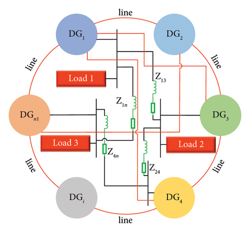
In Figure 1, Zij represents the impedance between DGs and Loadi represents the load of each node, and information exchange between different DGs is achieved through line connections.
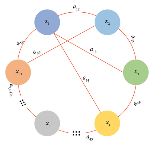
For ease of analysis, the small-world network topology of the PV microgrid system is equivalently represented, as shown in Figure 2. We consider DGi in the system as an agent node, represented by xi, and aij represents the interaction between nodes.
3. Finite-Time Consensus Pinning Control Method
3.1. Design of Finite-Time Consensus Pinning Controller
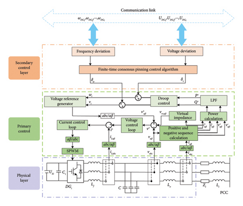
The schematic block diagram of the power secondary controller based on the finite-time pinning control method is shown in Figure 4.


3.2. The Selection of Pinning Nodes
Figure 5 illustrates the sets and variables under multiple pinning nodes.
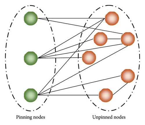
Through the above analysis, it can be seen that the upper bound of ψ(Z) is the increasing function of the pinned node degree and the pinning gain. When the pinning gain g is huge, the upper bound of the spectral radius of ψ(Z) will satisfy the condition that di/N is bounded, di is the degree of the pinned node, and di < N − 1. The lower bound of ψ(Z) is a strictly decreasing function of from the pinned node to the farthest unpinned node. From the above analysis, it can be seen that pinning a node with a large out-degree and a short distance from other nodes will result in a more extensive range of spectral radius, indicating a better pinning control effect.
Based on this inference, the following constraint node selection algorithm can be designed. We define the variable names as follows.
Let σ∗ be the expected algebraic connectivity to Z. Since σ∗ ≤ maxout−deg ree, the least pinned DGs to realize faster convergence speed λ∗ can be expressed as σ⋆ ≤ deg(Nodepinned)/(N − 1). Therefore, in order to achieve a faster convergence speed, the sum of the maximum out-degree of the least pinned DGs b should exceed (N − 1)σ∗. The pseudocode of the algorithm is as follows (Algorithm 1).
-
Algorithm 1: Pinning nodes selection algorithm.
- 1.
Sort the node degrees of DG
-
- 2.
Let b be the smallest integer
-
- 3.
- 4.
when |Nodepinned| < b
- A.
- B.
- 5.
if L + GZ ≥ σ⋆IN,stop;
-
Otherwise, let b = b + 1 and return to Step 4
4. Finite-Time Stability Analysis
The stability of the finite-time consensus pinning control method is verified by the Lyapunov stability theory. The following lemmas and theorem are given before the proof.
Lemma 1 (see [46].)For a normal number , if exists such that and ‖ei(t)‖ ≡ 0 remain constant, then the complex network (4) is finite-time synchronized.
Lemma 2 (see [46].)For x1, x2, x3, …, xn ∈ Rn,
Theorem 1 (see [47].)Assuming a positive definite continuous function V(t), and , where, γ > 0 and 0 < β < 1, it can be deduced that
Since L + GZ is a negative definite matrix, a global asymptotically stable equilibrium point exists for the microgrid system. Combining Lemmas 1 and 2 and Theorem 1, it can be proven that the control system can realize power consensus within the finite time.
5. Simulation Experiment Analysis
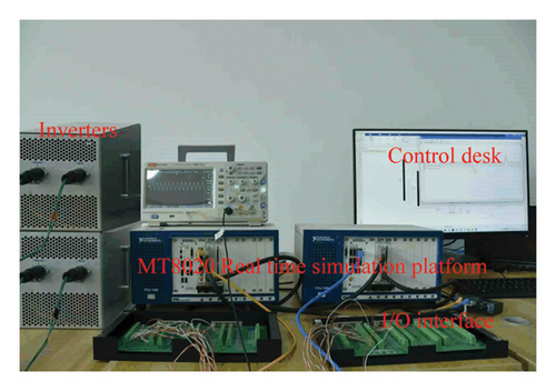
To verify the effectiveness of the finite-time consensus pinning control method based on complex networks for PV microgrids, it is tested in the MT 8020 semiphysical simulation experimental platform. This experimental platform has an 8-core Intel Xeon with a clock speed of 3.8 GHz and 32 GB DDR4 SDRAM. A microgrid system consisting of five PV inverters connected in parallel with a capacity ratio of 3:3:2:2:1 for each DG is built in StarSim HIL. The semiphysical simulation platform is shown in Figure 6.
The reference voltage and reference frequency of the PV microgrid system were set to 380 V and 50 HZ, respectively.
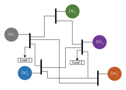
Figure 7 is the diagram of the test system, while the communication topology of the system established by employing the complex network theory is shown in Figure 8.

The parameters of DG, line, and load of the PV microgrid system are shown in Tables 1 and 2.
| DGs | Symbol | DG1 and DG2 | DG3 and DG4 | DG5 |
|---|---|---|---|---|
| k1i | 4 × 10⁻⁵ | 3 × 10⁻⁵ | 2 × 10⁻⁵ | |
| k2i | 1.6 × 10⁻³ | 1.2 × 10⁻³ | 0.8 × 10⁻³ | |
| RC/Ω | 0.03 | 0.03 | 0.03 | |
| LC/mH | 0.35 | 0.35 | 0.35 | |
| Rf/Ω | 0.1 | 0.1 | 0.1 | |
| Lf/mH | 1.35 | 1.35 | 1.35 | |
| Cf/μF | 50 | 50 | 50 | |
| Pmax/kW | 15 | 10 | 5 | |
| Qmax/kVar | 12 | 8 | 4 | |
| Load 1 | Load 2 | |||
| Loads | 20 kW + 13 kVar | 24 kW + 20 kVar | ||
| Lines | Line 1 & 3 | Line 2 | Line 4 | Line 5 |
|---|---|---|---|---|
| Rl/Ω | 0.51 | 0.23 | 0.51 | 0.35 |
| Ll/μH | 1.05 | 0.318 | 1.05 | 0.7 |
5.1. System Dynamic Performance Verification
According to the pinning node selection algorithm designed in this paper, the expected algebraic connectivity of the reference node is σ∗ = 0.09. is calculated by the node selection algorithm, which means that the node DG1 and the node DG3 are used as pinning nodes at the same time. Since there are two constraint nodes at this time, it is necessary to make a choice between node DG2 or node DG3 in the first iteration calculation result. If DG2 is used as the start, is the node set without DG2, route = 4, and .
Thus, can be used as the pinning node. If node DG3 is used as the start, is the node set without DG3 and . It can be concluded that both node {DG2, DG4} and node {DG1, DG3} can be used as constraint nodes to effectively control the system.
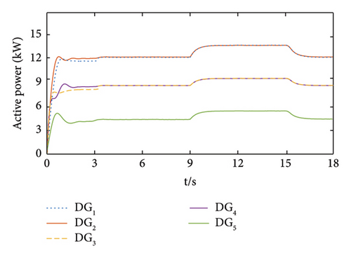
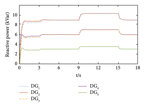
The simulation process is divided into the following four stages: (1) 0 − 3 s,only the primary control is activated; (2) after 3 s, finite-time consensus pinning secondary control is consistently implemented; (3) load of 6 kW + 5.5 kVar is cut-in in the system; and (4) load of 6 kW + 5.5 kVar is cut-off from the system.
The system running result with node {DG1, DG3} as the pinning node is shown in Figure 9.
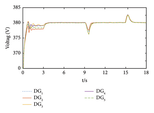
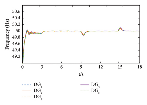
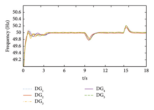
From Figures 9(a) and 9(b), it can be seen that due to the varying line impedances, the system cannot stabilize the voltage at the rated value solely through droop control during the 0–3 s time period, and there is also a certain deviation in frequency. After 3 s, the finite-time pinning control is added, the voltage value of each node is stabilized to 380 V within 0.9 s, and the frequency reaches the rated value of 50 Hz. After the load is cut-in at 9 s, although the voltage and frequency of the system decreased to varying degrees, relying on finite-time pinning secondary control, the voltage/frequency recovered to their rated values within 1.13 s. After the cut-off of the load, the voltage and frequency of the system increased and recovered to their rated values within 1.24 s. From this, it can be seen that the proposed control method has strong robustness and can quickly and effectively suppress load fluctuations in the system.
The active and reactive power balance control results for each DG output are shown in Figures 9(c) and 9(d). As seen in Figures 9(c) and 9(d), the system only relies on the droop control to share the output power before the secondary control starts. Due to the difference in the impedance parameters of the branches, the power cannot be shared proportionally according to the rated capacity of each DG. However, with the introduction of the finite-time pinning secondary control, active and reactive power can achieve power sharing in the ratio of 3:3:2:2:1. To further validate the dynamic performance of the proposed control method, a 6 kW + 5.5 kVar load was cut-in at t = 9 s and then cut-off at t = 15 s. From Figures 9(c) and 9(d), it can be seen that after load cut-in, the active power of each DG can achieve stable output under proportional distribution within 1.13 s, and the reactive power can achieve stable output within 1.24 s, and the output power is shared proportionally.
After load cut-off, the active power and reactive power of the system can still quickly achieve stabilization and power sharing according to the capacity ratio, indicating that the proposed control method has good dynamic performance.
5.2. Different Pinning Nodes’ Control Effects Comparison
To verify the influence of different constraint nodes on the control effect, DG4 and DG5 were used as pinning nodes for control. The simulation results of the system’s voltage and frequency are shown in Figures 10 and 11.
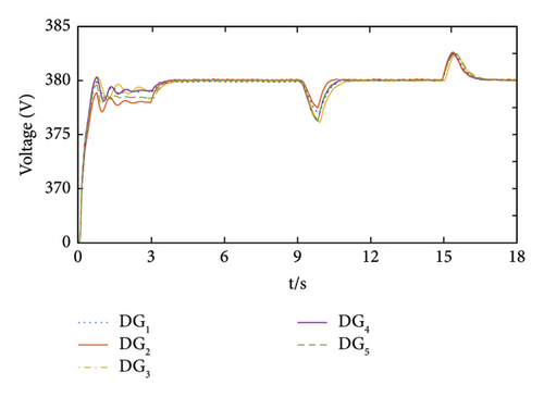
From Figure 10, it can be seen that when finite-time pinning control is applied to nodes {DG4, DG5} compared to applying pinning control to nodes {DG1, DG3}, although the system voltage can be stabilized around the rated value, the fastest convergence is 1.83 s and the smallest peak deviation is 3.23 V at load cut-in. The fastest convergence at load cut-off is 1.62 s and the smallest peak deviation is 2.45 V.
From Figure 11, it can be seen that when node {DG4, DG5} is selected as the pinning node, the frequency of each DG in the system can be stabilized at the rated value, eliminating the bias that exists in the primary sag control. However, the dynamic performance of the system in terms of convergence speed and peak deviation is not as good as taking nodes {DG1, DG3} as pinning nodes when there is a sudden change in load.
Table 3 shows the comparison results of the convergence speed and peak deviation of system voltage after selecting different constraint nodes. As can be seen in Table 3, compared with choosing {DG4, DG5} as pinning nodes, when the load is cut-in, the convergence time of DG1 to DG5 improved by 0.78, 0.79, 0.91, 0.71, and 0.45 s, respectively. When the load is cut-off, the convergence time of DG2, DG4, and DG5 improved by 0.59, 0.59, 0.54, 0.26, and 0.13 s, respectively. In addition, it can be seen that when the load is cut-in, the peak deviation of DG1 to DG5 improved by 10.2%, 9.8%, 3.1%, 3.4%, and 2.5%, respectively. When the load is cut-off, the peak deviation of DG1 to DG5 improved by 5.4%, 11.3%, 9.8%, 1.8%, and 3.6%, respectively. It can be concluded that the proposed finite-time pinning control method has better dynamic performance.
| Pinning node | Items | DGi | DG1 | DG2 | DG3 | DG4 | DG5 |
|---|---|---|---|---|---|---|---|
|
Convergence time (s) | Load cut-in | 0.91 | 0.93 | 0.92 | 0.95 | 1.13 |
| Load cut-off | 0.94 | 0.96 | 1.08 | 1.15 | 1.24 | ||
| Peak deviation (V) | Load cut-in | 2.46 | 2.55 | 3.13 | 2.83 | 2.75 | |
| Load cut-off | 2.1 | 2.05 | 2.21 | 2.14 | 2.15 | ||
|
Convergence time (s) | Load cut-in | 1.69 | 1.72 | 1.83 | 1.66 | 1.58 |
| Load cut-off | 1.53 | 1.55 | 1.62 | 1.41 | 1.37 | ||
| Peak deviation (V) | Load cut-in | 2.74 | 2.83 | 3.23 | 2.93 | 2.82 | |
| Load cut-off | 2.22 | 2.31 | 2.45 | 2.18 | 2.23 | ||
The above simulation experiment results verify the accuracy of the pinning node selection algorithm proposed in this paper and demonstrate the superiority of the finite-time pinning control method. These results are consistent with the conclusions drawn in Section 5.1.
5.3. Different Control Methods’ Control Effects Comparison
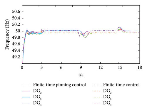
The dynamic response performance of the traditional finite-time secondary control is compared with the finite-time pinning secondary control, and the results are shown in Figures 12 and 13. Due to the large number of system nodes, nonpinned nodes are selected for analysis and comparison in order to verify the effectiveness of the finite-time pinning control method. It should be noted that the dashed line in the Figures 12 and 13 is the finite-time secondary control, and the solid line is the finite-time pinning secondary control.
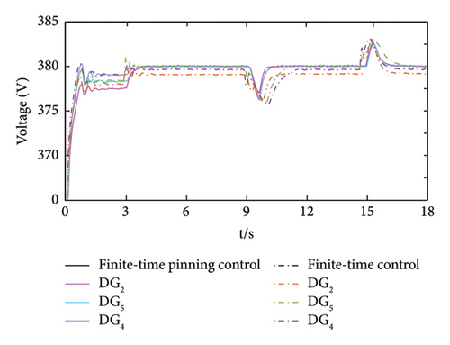
From Figure 12, it can be seen that the voltages at each node in the system have different degrees of deviation when relying only on the droop control. After the introduction of secondary control, the finite-time secondary control is able to stabilize the voltage. However, it has a significant deviation and cannot stabilize the voltage at the rated value. When the load is cut-in, the system takes 2.8 s to achieve voltage stabilization when the finite-time control method is used, and the maximum deviation of the peak voltage reaches 4.8 V.
After the cut-off of the load, the system takes 2.2 s to achieve voltage stabilization when the finite-time control method is used, and the maximum deviation of the peak voltage reaches 3.5 V. When the finite-time pinning secondary control is adopted, the voltage of each node in the system can be quickly recovered to the rated value, and the fluctuation generated during the recovery process is negligible. When the load is cut-in, the PV microgrid system can recover to the rated value in only 1.1 s, with a maximum voltage deviation of 3.8 V. When the load is cut-off, it only takes 1.2 s for the system to recover to its rated value, with a maximum voltage deviation of 2.9 V.
Table 4 shows the comparison results of the convergence speed and peak deviation of system voltage of different control methods. As can be seen in Table 4, compared to the traditional finite-time control method, when the load is cut-in, the convergence time of DG2, DG4, and DG5 improved by 1.84, 2.46, and 1.41s, respectively, as the finite-time pinning control method was implemented. When the load is cut-off, the convergence time of DG2, DG4, and DG5 improved by 1.99, 1.96, and 1.4s, respectively. In addition, it can be seen that when the load is cut-in, the peak deviation of DG2, DG4, and DG5 improved by 10.1%, 23.7%, and 25.9%, respectively. When the load is cut-off, the peak deviation of DG2, DG4, and DG5 improved by 7.7%, 15.9%, and 10.2%, respectively. It can be concluded that the proposed finite-time pinning control method has better dynamic performance.
| Control methods | Finite-time pinning control | Finite-time control | ||||
|---|---|---|---|---|---|---|
| Load variation | Load cut-in | Load cut-off | Load cut-in | Load cut-off | ||
| Control nodes | DG2 | Convergence time (s) | 0.31 | 0.22 | 2.15 | 2.21 |
| Peak deviation (V) | 3.72 | 2.51 | 4.14 | 2.72 | ||
| DG4 | Convergence time (s) | 0.28 | 0.21 | 2.74 | 2.17 | |
| Peak deviation (V) | 3.32 | 2.38 | 4.35 | 2.83 | ||
| DG5 | Convergence time (s) | 0.32 | 0.31 | 1.73 | 1.71 | |
| Peak deviation (V) | 3.57 | 2.47 | 4.82 | 2.75 | ||
Figure 13 shows the frequency comparison of the system using different control methods. From Figure 13, it can be seen that the system’s frequency cannot be stabilized at the rated value when finite-time secondary control is used, whereas finite-time pinning secondary control can quickly recover the frequency at each node to the rated value.
When the system load changes abruptly, the convergence speed of the finite-time secondary control is significantly slower, and there are large fluctuations in the recovery process, which affects the stability of the system.
From the analysis of the above simulation experimental results, it is concluded that the finite-time pinning control method has a faster convergence speed and smaller peak deviation when the load changes abruptly, and the overall dynamic performance of the system is significantly better than the finite-time secondary control method.
6. Conclusions
In this paper, problems such as unbalanced power sharing caused by different line parameters and unsynchronization between nodes in a PV microgrid system (a typical CPS system) consisting of multiple parallel inverters are studied. A finite-time consensus pinning control method for PV microgrids based on the complex network theory is proposed to achieve coordination control of multiagent systems. A small-world network model of a PV microgrid system was constructed based on the complex network theory, and a selection algorithm for constrained nodes was proposed to overcome the subjectivity of selecting constrained nodes based on expert experience. Finally, a semiphysical simulation platform is built in StarSim HIL, relying on the MT8020 simulator. It is verified that the finite-time pinning control method can achieve stable voltage and frequency control in finite-time, enabling the deviation of the droop control to recover to the rated value quickly. The finite-time pinning control method can realize the balanced control of active and reactive power when the system load changes abruptly, and it also shows that the system has strong robustness and good dynamic response speed. The experimental results show that the peak deviation improved by 7.7% at least, and the convergency time improved by 1.4 s at least, compared to the traditional finite-time control method.
Future work will consider methods for the coordination control of PV microgrids with nonfixed topologies, considering the impacts of volatile electricity prices and extreme weather. As the typical CPS, the influence of the network attacks such as denial of service (Dos) and false data injection attacks (FDIAs) should be also considered in the future work.
Conflicts of Interest
The authors declare no conflicts of interest.
Author Contributions
Xiping Ma received the M.Eng. degree, specializing in electrical engineering. His research direction is a new energy grid connection. He is currently working at the Electric Power Research Institute, State Grid Gansu Electric Power Company.
Chen Liang received the M.Eng. degree, specializing in electrical engineering. His research direction is power loss reduction and energy conservation. He is currently working at the Electric Power Research Institute, State Grid Gansu Electric Power Company.
Xiaoyang Dong received the M.Eng. degree, specializing in electrical engineering. His research direction is new energy grid-related testing. He is currently working at the Electric Power Research Institute, State Grid Gansu Electric Power Company.
Yaxin Li received the M.Eng. degree, specializing in electrical engineering. Her research direction is power grid line loss technology. She is currently working at the S Electric Power Research Institute, State Grid Gansu Electric Power Company.
Funding
This work was supported by the Science and Technology Project of Headquarters of the State Grid Corporation, no. 5400-202333241A-1-1-ZN.
Open Research
Data Availability Statement
The data used to support the findings of this study are available from the corresponding author upon reasonable request.


