Numerical Analysis, Experimental Validation, and Application of DC Interruption With Parallel Vacuum Interrupters
Abstract
Large-capacity high voltage direct current circuit breakers (HVDC CBs) are critical equipment for achieving reliable operation of future multiterminal HVDC systems. The objective of this paper is to investigate the interruption characteristics of DCCB with parallel vacuum interrupters. In this paper, the proposed vacuum interrupter is modeled in detail and simulated in the PSCAD environment by taking into account the positive volt-ampere characteristics of the vacuum arc, the current transfer characteristics, and the current sharing characteristics between parallel vacuum interrupters. Then, the vacuum interrupter model is validated by experimental results. The performance of two types of large-capacity multimodule DCCBs is compared regarding operating reliability and actuator decentralization. Meanwhile, the current stress on the VSC branch and the DC interruption characteristics are analyzed. The comparison results show that the 6-module DCCB with series followed by parallel structure is more suitable for high voltage and large-capacity systems. In ±160 kV 4-terminal flexible DC grid, two typical DC fault interruption characteristics of the 6-module DCCB with series followed by parallel structure are simulated and analyzed. The results validate that the multimodule DCCB with series followed by parallel structure has better DC fault interruption performance in multiterminal HVDC systems.
1. Introduction
In recent years, the demand for renewable energy connections such as offshore wind farm and photovoltaic power plant has been gradually growing due to limited energy reserves, high cost, and environmental pollution problems [1]. The rapidly developing multiterminal flexible direct current (MTDC) transmission technology based on voltage source converter (VSC) provides a powerful solution for multiple renewable energy power stations to transmit power to multiple terminals [2, 3]. MTDC systems have a low impedance, resulting in higher fault current rise rates and larger peak values when short-circuit faults occur [4]. The vacuum interrupter (VI)-based direct current circuit breaker (DCCB) is critical equipment to protect the safe and stable operation of the MTDC system. To realize the timely interruption of DC fault, higher voltage and larger-capacity requirements for HVDC CBs are put forward [5, 6].
There are two main methods to promote DCCBs to higher voltage levels. One is to develop single-break DCCBs for higher voltage levels, and the other is to develop multibreak DCCBs [7, 8]. Since SF6 is a strong greenhouse gas and is a crucial factor contributing to global warming [9, 10], vacuum circuit breakers (VCBs) have become an ideal choice to replace SF6 CBs in higher voltage levels [11]. However, due to the saturation effect between the breakdown voltage of a VI and its vacuum gap, increasing the dynamic and static contact gaps cannot achieve a linear increase in the rated voltage level of single-break VCBs [12, 13]. The voltage level of the existing single-break VCB is limited to 145 kV [14], and further research is underway for a higher-grade 252 kV single-break VCB. In contrast, the multibreak VCB can fully utilize the insulation and arc extinguishing performance of the series vacuum short gap. As a result, the limitation of saturation effect is eliminated, and higher voltage levels can be achieved [15]. Ai et al. proposed a novel 6-break VCB by connecting VIs in series to increase the voltage level to 363 kV [16, 17], and uniform voltage distribution is effectively improved by connecting grading capacitors in parallel at each break [18].
The high-temperature rise due to high heat generation and limited heat transfer performance is a crucial constraint to the current-carrying ability of individual VI [19, 20]. Therefore, the scheme of connecting VIs in parallel to share the rated and fault current has been proposed. Due to the significant negative resistance characteristics of SF6, the parallel connection of two gas interrupters (GIs) will increase the nonuniformity of the branch current [21]. In contrast, the vacuum arc has positive volt-ampere characteristics, which have a positive effect on balancing the parallel branch current [22] and contribute to the upgrading of DCCB current-carrying and interrupting performance [23, 24]. Zheng et al. modeled the current transfer process of a hybrid generator circuit breaker (HGCB) consisting of GI and VI in parallel [25]. The effects of different fault current types, arc voltages, and other factors on the current transfer time were investigated [26]. Smirnov et al. developed a vacuum arc and gas arc model for HGCB, and the effect of the contact separation moment of the GI on the current transfer time was investigated [27]. Liu et al. proposed a parallel VI scheme to cooperate in achieving generator circuit breaker (GCB) rated current-carrying and short-circuit current interruption. The reason for the arc initiation of the first operated VI was analyzed to be the change of current in the VI equivalent inductance [28]. Su et al. investigated the current uniformity characteristics of the parallel GCB based on highly coupled split reactors. They pointed out that the operating time difference between the operation of parallel VI and the differences in branch parameters have little influence on the current uniformity [5]. Han et al. proposed a large-capacity GCB scheme consisting of 6 VIs connected in parallel, and the current sharing of the static current-flow process, the current sharing of the dynamic arcing process, and the influence of external electromagnetic field on current sharing were analyzed [29].
Currently, the study mainly focuses on the parallel GCB for AC interruption, and the influence of the relevant parameters of each branch on the current uniformity and transfer time is investigated. For multimodule DCCB composed of multiple VIs connected in series and parallel, the study of DC interruption transient characteristics has not yet been reported.
The objective of this paper is to investigate the DC interruption transient characteristics of the multimodule DCCB. The rest of the paper is organized as follows: Section 2 presents a detailed mechanism of parallel current transfer, focusing on the current transfer and sharing stages. The VI in the 0–20 kA range is modeled, and the current simulation of parallel VI in comparison with experimental results is shown in Section 3. In Section 4, two types of multimodule DCCB are modeled, analyzed, and compared in terms of operating reliability and current uniformity characteristics. Then, the multimodule DCCB with series followed by parallel structure is simulated and verified in a 4-terminal MTDC system. Finally, conclusions based on the results of the study are presented in Section 5.
2. Mechanisms of Current Transfer in Parallel VIs
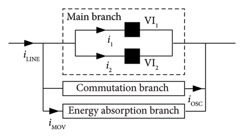
The parallel DCCB is mainly composed of the main branch, commutation branch, and energy absorption branch in parallel. The main branch comprises two or more parallel vacuum interrupters, VI1 and VI2, for normal conduction of line current iLINE. The commutation branch generates oscillation current iOSC, which is superimposed inversely with iLINE, creating an artificial over-zero point to extinguish the arc. The energy absorption branch consists of surge arresters (SAs) with good nonlinear volt-ampere characteristics, absorbing the residual energy in the system after interruption.
Figure 1 illustrates the principal diagram of the parallel DCCB, where iLINE is the line current through the DCCB, i1 is the current through the VI1, i2 is the current through the VI2, iOSC is the oscillation current in the commutation branch, and iMOV is the current through the energy absorption branch.
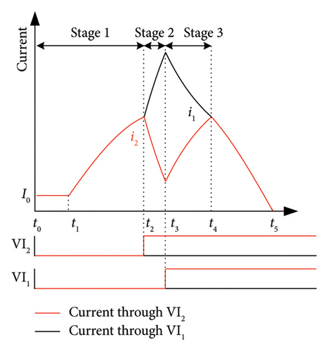
The current interruption process of the parallel DCCB can be divided into 3 stages according to whether VIs are operated or not. This section mainly analyzes the abovementioned three stages. Stage 1 is both parallel VIs are not operated. Stage 2 is when either VI is operated, and current transfer occurs in the two parallel branches. Stage 3 is when both VIs are operated, and current sharing occurs naturally. This section analyzes the abovementioned three stages specifically.
-
t0 − t1: at this stage, both VI1 and VI2 are closed. The two parallel branches share the line current equally, and i1 = i2 = I0 exists.
-
t1 − t2: the fault occurs at the instant of t1; therefore, iLINE starts to increase gradually, and i1 and i2 also rise gradually and always share iLINE equally. Due to the decentralization of the actuators, the two VIs are opened at different moments.
-
t2 − t3: this stage is the current transfer stage. At t2, VI2 is opened and VI1 remains in the closed state. An arc is generated between the movable and static contacts of VI2. The arc voltage leads the current to be transferred to the branch where VI1 is located, as shown in the gradual decrease of i2 and the gradual increase of i1.
-
t3 − t4: this stage is the current sharing stage. Both VI1 and VI2 are opened at t3. Since the vacuum arc has a positive volt-ampere characteristic, the arc voltage between the VI1 contacts is higher than the arc voltage between the VI2 contacts. Therefore, the arc voltage difference leads to a gradual increase in i2 and a gradual decrease in i1. It reaches i1 = i2 at t4.
-
t4 − t5: the two parallel branches achieve the current uniformity again, shown as i1 = i2. Then, the current crosses the zero point at t5.
2.1. Stage 1
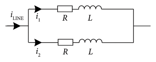
During regular operation of the DC power system, the main branch of the DCCB conducts, and the two parallel VIs share the iLINE. R1 and L1 are the equivalent impedance of the branch where VI1 is located, and R2 and L2 are the equivalent impedance of the branch where VI2 is located. Helmer and Lindmayer pointed out that the parasitic capacitance across the gap of VI is 0.2 nF [30]. Thus, the current through the capacitors can be neglected due to the small capacitance value and small change in vacuum arc voltage.
2.2. Stage 2
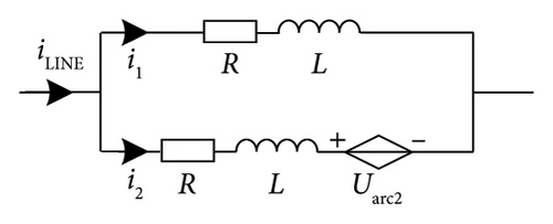
Due to the decentralization of the actuator, it is not easy to open the contacts of the two parallel VIs simultaneously. VI2 is opened at t2, an arc will be generated between the contacts of VI2, and the arc voltage is Uarc2. At the instant, VI1 remains closed. Therefore, branch impedances R and L only exist. The corresponding equivalent circuit model is shown in Figure 4.
2.3. Stage 3
VI1 is opened at t3, and the arc begins to generate between the contacts of VI1. The arc voltage is Uarc1. Currently, the two parallel branches are in the arcing state. The corresponding equivalent circuit model is shown in Figure 5.
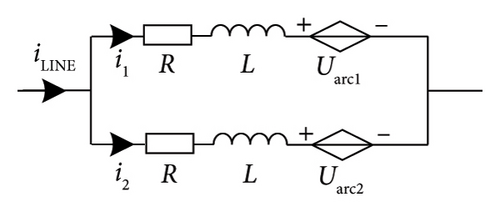
The current sharing phenomenon between VIs is due to the vacuum arc having a positive volt-ampere characteristic, which means the arc voltage increases with the increase of arc current. As the VI1-operating moment lags behind VI2, there has been i1 > i2. At the instant, the arc voltage difference exists between the two parallel branches. After VI1 is operated, the voltage difference leads i1 to transfer to the branch where VI2 is located.
Comparing equations (5) and (11), the current difference of i1 is iave. It can be seen that the current sharing phenomenon between the two parallel VIs is due to the new generation of Uarc2 based on Stage 2, which is supported by the form of iave.
3. Modeling and Experimental Validation of Current Transfer
3.1. Numerical Modeling of Vacuum Arc
The VI model is first established according to the state of VI, and the current interruption process is simulated and investigated. The state of the VI can be divided into three categories, namely, the closed state, the arcing state, and the open state. The equivalent parameters of the VI model in the different states above are shown in Table 1.
| Parameters | Label | Value | Unit | ||
|---|---|---|---|---|---|
| Close | Arcing | Open | |||
| Branch resistance | R | 8 × 10⁻⁵ | 8 × 10⁻⁵ | 106 | Ω |
| Branch inductance | L | 2 | 2 | 2 | μH |
| Arc voltage | Uarc | / | (12) | / | V |
3.2. Experiment Setup
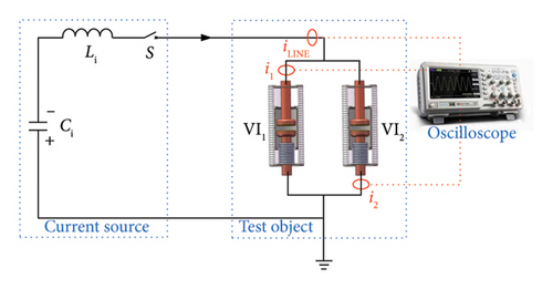
As shown in Figure 6, the synthetic experimental current source circuit comprises current source capacitance Ci, current source inductance Li, and 12 kV closing switch CB0 in series. The specific values of each parameter are shown in Table 2.
| Parameters | Label | Value | Unit |
|---|---|---|---|
| Current source capacitance | Ci | 55.76 | mF |
| Current source inductance | Li | 0.1867 | mH |
| Charging voltage of Ci | 1.6 | kV | |
| Frequency of fault current | f | 50 | Hz |
The test object consists of two parallel vacuum interrupters VI1 and VI2. One terminal of the test object is connected to the current source, and the other terminal is directly grounded. CB0 is disconnected, and Ci is precharged before the test starts. When the test begins, CB0 is closed. At which instant, the current source circuit is conducted, and the test current is generated by discharging the precharged Ci.
3.3. Test Results and Analysis
The test results for the current interruption of the two parallel VIs are shown in Figure 7. In this test, the short-circuit current starts to be generated by the current source at t = 0 ms, and VI1 and VI2 carry iLINE on average.
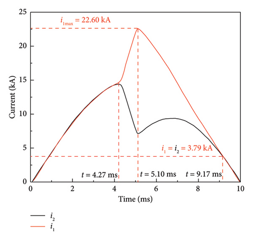
At t = 4.27 ms, VI2 receives a trip signal. VI2 opens and an arc is generated between the movable and static contacts of VI2, VI1 remains in the closed state. At this instant, the arc voltage at the break leads to a current transfer, corresponding to a gradual decrease in i2 and a gradual increase in i1. At the instant of t = 5.1 ms, the peak value of i1 increases to 22.6 kA, and VI1 receives the trip signal to operate. Both VI1 and VI2 are in the arcing state. Since the vacuum arc has a positive volt-ampere characteristic, the arc voltage generated between the contacts of VI1 after the operation is relatively higher than that of VI2. Therefore, the arc voltage difference between the two parallel branches leads i2 to increase gradually and i1 to decrease progressively. As seen in Figure 7, i1 = i2 = 3.79kA, and the two parallel branches achieve current uniformity again at the instant of t = 9.17 ms. At t = 10 ms, the current through VI1 and VI2 crosses zero, and the arc is extinguished.
VI is replaced in the PSCAD with the model consisting of a resistor, an inductor, and a voltage source in series. The test circuit shown in Figure 6 is also constructed, and the operating timing of the two parallel VI is set in the same as the experiments by delaying the operation of VI1 compared with VI2. Figure 8 shows the comparison of simulated and experimental results for i1and i2 in the current transfer and sharing process.
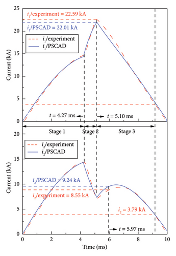
It can be seen that the simulated peak value of i1 is 22.01 kA at t = 5.10 ms, which is decreased by 2.57% compared with the tested peak value of i1 = 22.59 kA. In addition, the maximum difference between the simulation and experiment results of i2 is in the current sharing process, which is 9.24 kA at t = 5.97 ms, and the error calculated is around 7.47%. There are slight differences between the measured and simulated current of i1 and i2, which stems primarily from the complicated variation process of arc combustion and extinction cannot be simulated accurately in the PSCAD environment. The actual influence of the arc mode, plasma density, contact surface temperature of VI, multiple physical fields, etc. is neglected when using equation (12) to represent the arcing state of VI.
In practice, VI is driven by an actuator to achieve opening and closing, the actuator consists of a moving conductive rod, an insulating rod, an opening and closing coil, a repulsion metal plate, and the charging capacitors for the two coils. Due to the deviations in the assembly process of the abovementioned key components composing the VI, decentralization also exists in the multiple operations for a single actuator. In the test, the decentralization of the ultrafast VI is no more than 50 μs when a single actuator is operated several times. In addition, the difference in the operating moments of the two parallel VI is described as the actuator decentralization, which is affected by factors such as the capacitance value of the storage capacitor, the charging voltage deviation, and the machining size deviation of the components, and is usually does not exceed 1 ms. It can be seen that the operating decentralization of the two VIs in Figure 8 is 0.91 ms.
It can be seen that the simulated current results and the experimental measurements are in good agreement during the whole test process. Therefore, the constructed model can continue to be applied to represent VI in the large current interruption simulation of multimodule DCCB. Then, DC interruption transient characteristics of the multimodule DCCB can be simulated and analyzed.
4. Performance Comparison of Two Types of Multimodule VARC DCCB
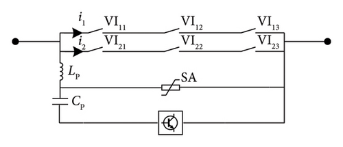
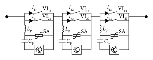
To adapt to the higher voltage level requirements of the system, several VIs are connected in series to satisfy the N-1 criterion and avoid overall failure due to a VI failure. In addition, VIs are connected in parallel to meet the higher requirements of rated current-carrying performance and short-circuit current interruption performance. Therefore, there are two types of structure for multimodule DCCBs, as shown in Figure 9, namely, series followed by parallel, and parallel followed by series.
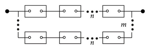
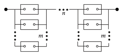
Figure 9(a) shows the type of series followed by parallel structure. n VIs are connected in series to constitute a branch, and the same m branches are connected in parallel to constitute the main branch of DCCB. Figure 9(b) shows the type of parallel followed by series structure. m VIs are connected in parallel to constitute a unit, and the same n units are connected in series to constitute the main branch of DCCB.
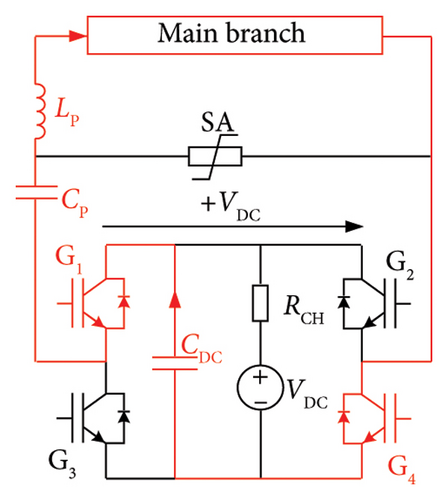
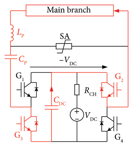
Ängquist et al. proposed the concept of VSC-assisted resonant current (VARC) DCCB and elaborated on the constitute and working principle of VARC DCCB [35, 39]. VARC DCCB consists of three branches in parallel, namely, the main branch, the commutation branch, and the energy absorption branch. The main branch comprises VIs in series and parallel, and the line current flows through the main branch during the normal operation of VARC DCCB. The commutation branch consists of two parts, as shown in Figure 10. The first part is an oscillation circuit composed of an oscillation capacitor (CP) and an oscillation inductor (LP). The second part is a VSC, an energy storage capacitor (CDC), and a charging circuit (VDC, RCH) for CDC. CDC is precharged before the operation of VARC DCCB. The energy absorption branch consists of SAs, absorbing the residual electromagnetic energy stored in the system.
Currently, the rated voltages of several typical MTDC systems are 160, 320, and 550 kV. Using 80 kV VI to constitute a branch of the DCCB main branch, it is necessary to connect 2 VIs in series to extend the rated voltage of the DCCB to 160 kV. After considering redundancy to satisfy the N-1 criterion in a 160 kV MTDC system, 3 VI modules of 80 kV are required for a branch of the DCCB main branch. Similarly, a branch of the DCCB main branch applied in the MTDC system at 320 kV and 550 kV consists of 5 VI modules of 80 kV and 8 VI modules of 80 kV in series, respectively. The number of branches in parallel to constitute the main branch is determined by the MTDC system and the rated short-circuit interruption current of the VI. The optimal number of VI modules required for the DCCB altogether is the product of the number of parallel branches of the main branch and the number of VIs in one branch.
To satisfy the 160 kV/20 kA system voltage and current interruption requirements, the main branch of the 160 kV VARC DCCB requires a total of 6 VIs of 80 kV/10 kA connected in series and parallel. Figure 11(a) shows the 160 kV 6-module VARC DCCB with series followed by parallel structure, the main branch of which constitutes 2 branches in parallel, and each branch consists of 3 VIs in series. The 160 kV 6-module VARC DCCB with parallel followed by series structure is shown in Figure 11(b), the main branch of which constitutes 3 units in series, and each unit consists of 2 VIs in parallel. The rated voltage of the SA in Figure 11(a) is 160 kV, and the rated voltage of each SA in Figure 11(b) is 80 kV. The operating voltage of the SA is selected as 1.5 times the rated voltage of the DC power system.
4.1. Comparison of Operating Reliability
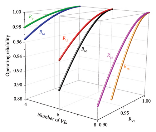
Figure 12 illustrates an example comparing the operational reliability of two types of 4-module, 6-module and 8-module DCCBs. Rc4, Rc6, and Rc8 are the operating reliability of the 4-module, 6-module, and 8-module DCCBs with series followed by parallel structure. Rb4, Rb6, and Rb8 are the operating reliability of the 4-module, 6-module, and 8-module DCCBs with parallel followed by series structure. Due to the low probability of VI failure, RVI is greater than 0.9. In Figure 12, it can be seen that Rc4 > Rb4, Rc6 > Rb6, and Rc8 > Rb8. Therefore, the operational reliability of multimodule DCCBs with series followed by parallel structure is always higher than that of multimodule DCCBs with parallel followed by series structure regardless of the number of VIs.
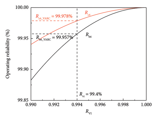
From Figure 13, the reliability of the 160 kV 6-module VARC DCCB with series followed by parallel structure is Rc6_VARC = 99.978%, higher than that of the 160 kV 6-module VARC DCCB with parallel followed by series structure. Therefore, the 160 kV 6-module VARC DCCB with series followed by parallel structure is more reliable. Similarly, the operating reliability of two types of DCCB can be calculated and compared at other voltage levels.
4.2. Comparison of Interruption Performance
The above two types of 160 kV 6-module VARC DCCB are modeled in the PSCAD environment, and the simulation model is shown in Figure 14. The rated voltage and rated current of the DC system are 160 kV and 1 kA, and the parameters are shown in Table 3.
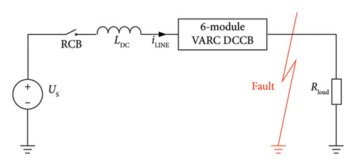
| DC system parameters | Label | Value | Unit |
|---|---|---|---|
| Source voltage | Us | 160 | kV |
| Inductance of fault current limiting reactor | LDC | 100 | mH |
| Load resistance | Rload | 160 | Ω |
| Fault resistance | Rfault | 0.1 | Ω |
The fault occurs at t = 20 ms, and the trip signal is sent to the 160 kV 6-module VARC DCCB at t = 22 ms. Then, actuators start to drive the separation of the VIs at the instant. The operating time of the 6 VIs is set to obey a general normal distribution with a mean µ = tmean = 3 ms and standard deviation σ = 20 µs so that the difference between the VI operating moments is within 50 µs. Figure 15 shows the current interruption simulation results corresponding to the two types of 160 kV 6-module VARC DCCB of Figure 11.
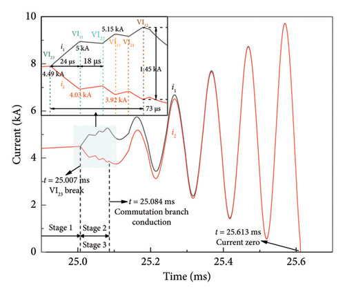
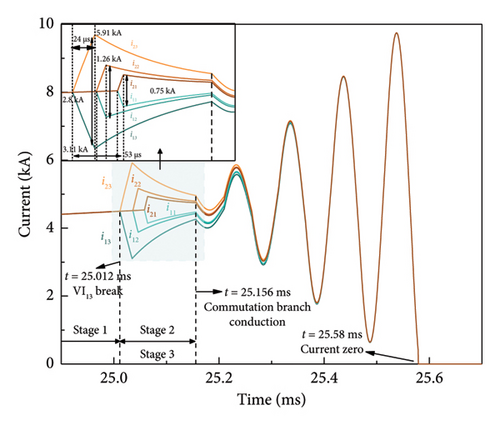
Figure 15(a) shows a typical current interruption simulation result for the 160 kV 6-module VARC DCCB with series followed by parallel structure. In the simulation, 6 VIs are operated sequentially in the order of VI23, VI11, VI22, VI13, VI21, and VI12. At t = 25.007 ms, i1 = i2 = 4.49 kA. At the instant, VI23 is opened first and a vacuum arc is generated between the contacts of VI23 and the remaining VIs are in the closed state. The arc voltage leads the current to transfer to the parallel branch, corresponding to a gradual decrease of i2 from 4.49 kA to 4.03 kA and a gradual increase of i1 from 4.49 kA to 5 kA. At t = 25.031 ms, VI11 is operated, and the vacuum arc is generated between its contacts. The arc voltage difference between the two parallel branches leads i1 and i2 tend to be gradually uniform. At the instant of t = 25.049 ms, VI22 is operated, and VI23 and VI22 on the same branch are arcing now. Since the arc voltage value of the short gap series is higher than that of the parallel branch, the current transfer occurs again. This is shown by a gradual decrease of i2 to 3.92 kA and a gradual increase of i1 to 5.15 kA based on the previous current sharing stage. Similarly, current sharing occurs again in the two parallel branches after VI13 is operated. At the instant, VI11 and VI13 on the same branch are arcing now. The variation trend of i2 and i1 is similar to the abovementioned situation after VI21 and VI12 are operated sequentially, corresponding to the third occurrence of the current transfer and sharing process. It can be seen that there is a time difference of 73 µs between the last operated VI12 and the first operated VI23. In the period, the maximum current difference between i1 and i2 is 1.45 kA, which occurs at the operating moment of the VI12. At t = 25.084 ms, VSC in the commutation branch is conducted, and the resulting gradual oscillation current is superimposed on the main branch in the reverse direction. In this process, i1 and i2 are gradually uniform. At t = 25.613 ms, an artificial over-zero point is generated, and i1 and i2 cross zero simultaneously.
Figure 15(b) shows a typical current interruption simulation result for the 160 kV 6-module VARC DCCB with parallel followed by series structure. In this simulation, 6 VIs are operated sequentially in the order of VI13, VI23, VI12, VI22, VI11, and VI21. At t = 25.012 ms, the current in each branch rises to 2.5 kA. At the instant, VI13 is opened first and a vacuum arc is generated between the contacts of VI13, the remaining VIs are in the closed state. Since VI13 and VI23 are connected in parallel, the arc voltage leads the current to transfer in the two branches, corresponding to i13 and i2 decreasing to 3.1 kA and i23 and i2 increasing to 5.91 kA. At t = 25.036 ms, VI23 is operated, generating a vacuum arc between its contacts. At the instant, both VI13 and VI23 in the third unit are arcing now. The arc voltage difference leads i13 and i23 to be gradually uniform. The maximum difference between i13 and i23 is 2.8 kA during the above period. Since none of the remaining VIs are operated, the parallel branches within each unit continue to share the current uniformly. When VI12 is operated, i12 gradually decreases and i22 gradually increases. The maximum difference between i12 and i22 is 1.26 kA. After VI22 is operated, both VI12 and VI22 in the second unit are arcing. Similarly, the arc voltage difference leads i12 and i22 to be gradually uniform. The current variation is similar when VI11 and VI21 are operated, corresponding to a maximum difference of 0.75 kA between i11 and i21. It can be seen that the time difference between the last operated VI21 and the first operated VI13 is 53 µs, and the current difference between i13 and i23 is the largest within the 3 VI units. The reason is that the operating time difference between VI13 and VI23 is relatively more prolonged, and the current transfer value is also more significant. At t = 25.156 ms, VSC in the commutation branch of each VI unit is conducted, and the resulting gradual oscillation current is superimposed inversely on the main branch. In this process, the current in the parallel branch is gradually uniform and finally crosses zero at t = 25.58 ms.
It can be seen that in Figure 15(a), i1 and i2 change accordingly when 6 VIs are operated. In Figure 15(b), the current variation within each VI unit is affected by the two parallel VIs of that unit. Multiple repetitive simulations are performed since the differences in the operating time of the 6 VIs are always variable.
To compare the interruption performance of the two types of 160 kV 6-module VARC DCCB, the values of Δi and Δt in 50 simulations are statistically obtained in Figure 16.
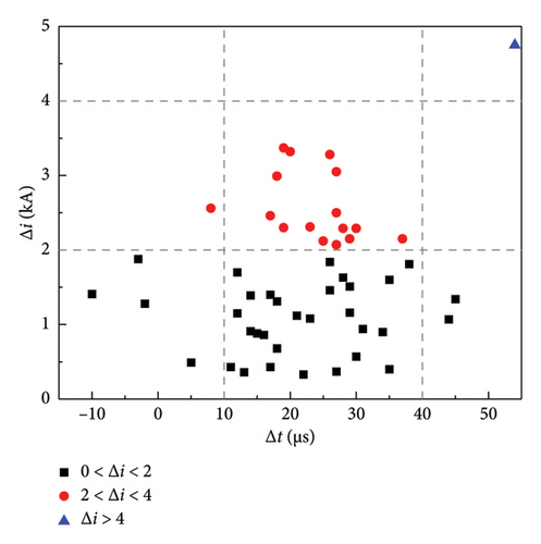
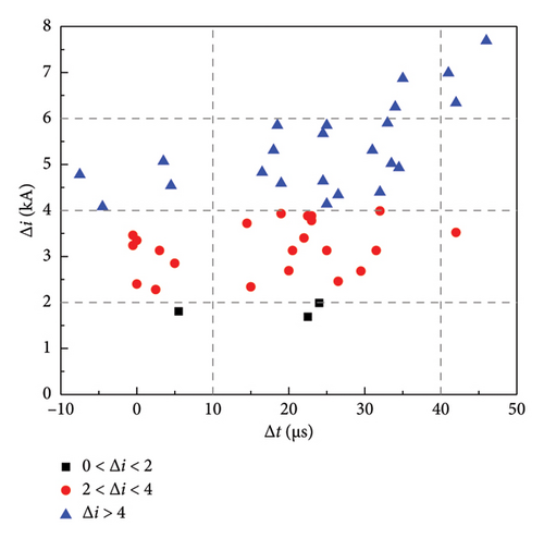
Figure 16(a) shows the variation of Δi when 160 kV 6-module VARC DCCB with series followed by parallel structure interrupts the current. The results indicate that the absolute value of the maximum difference between the parallel current Δi is basically in the range of 0–4 kA, where it is more in the range of 0–2 kA, accounting for 66% of the total number of simulations. Then, it is followed by 2–4 kA, which occurs 32% of the total number of simulations. While the case of Δi > 4 kA occurs only once. Figure 16(b) shows the variation of Δi when 160 kV 6-module VARC DCCB with parallel followed by series structure interrupts the current. The results indicate that the absolute value of the maximum difference between the parallel current Δi is more often between 2 and 6 kA, with occurrences between 2–4 kA and 4–6 kA accounting for 44% and 38% of the total number of simulations. Since the magnitude of the transferred current in the parallel branches is affected by the actuator decentralization, the occurrence time of Δi is always variable but within 10–40 µs after tmean, regardless of which VARC DCCB is used.
Compared with the 160 kV 6-module VARC DCCB with parallel followed by series structure, the absolute value of the maximum difference between the parallel current Δi of the 160 kV 6-module VARC DCCB with series followed by parallel structure is relatively more minor. Therefore, the 160 kV 6-module VARC DCCB with series followed by parallel structure exhibits better interruption performance during the high current interruption process. In addition, it has a mitigating effect on the current imbalance caused by the actuator decentralization, and it is also more suitable for high voltage and large-capacity DC power systems.
4.3. Comparison of the Energy Absorption
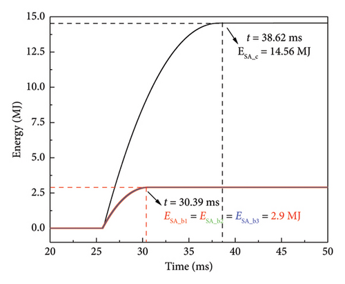
During the current interruption process, the system keeps charging CP until its voltage reaches the clamping voltage of SA when an artificial CZC is created in the arc current. Then SA starts to conduct and the line current is commutated into the energy absorption branch. Figure 17 illustrates the comparison of SA energy absorption for the two types of 160 kV 6-module VARC DCCB. ESA_c is the energy absorbed by SA in the VARC DCCB with series followed by parallel structure, and the absorbed energy of the SA is ESA_c = 14.56 MJ. ESA_b represents the absorbed energy of 3 SAs in the VARC DCCB with parallel followed by series structure, and the corresponding absorbed energy of each SA is 2.9 MJ. In this way, the total absorbed energy for 3 SAs is ESA_b = 2.9 × 3 = 8.7 MJ. It can be seen that ESA_c increases by 5.86 MJ over ESA_b, and it is increased by 40.25% compared with ESA_b. The cost and volume of the SA increase correspondingly. Moreover, the time taken for energy absorption is slightly affected by different operating voltages of SA. When an artificial CZC is created in the arc current, the system keeps charging CP, and its voltage increases gradually. Therefore, the voltage across VI also increases, accelerating the speed of the fault current drop to zero. In Figure 17, the time taken for the same energy absorption by SA in the VARC DCCB with series followed by parallel structure is shorter than that in the VARC DCCB with series followed by parallel structure.
4.4. Comparison of Costs
The economy of DCCB is particularly important in promoting its application in engineering. The cost of components for the two types of 160 kV 6-module VARC DCCB is estimated according to the marketing investigation of component prices, and the comparison results are presented in Table 4. The cost of each component is represented separately by the nominal value, and 10,000 USD corresponds to 1 p.u. The costs of VIs in the main branch are largely determined by the system voltage and current levels. Since the main branch in the two types of 160 kV 6-module VARC DCCB consists of 6 VIs of 80 kV, the part of the cost is the same and not considered. In addition, the cost of inductors can be neglected because the prices are much lower than that of capacitors. Therefore, only the cost of CP, CDC, and IGBTs are considered in the commutation branch. The cost of the capacitors is proportional to their capacity, and the price coefficient is generally taken as 0.22 USD/J [43]. The same type of IGBT (5SNA3000K452300, 4.5 kV, 3 kA, 6195.31 USD) [44] is selected to enable a fair comparison. The cost of SA is proportional to the magnitude of the absorbed energy, and the coefficient is 13.76 USD/kJ [45]. From Figure 17, the absorbed energy ESA_c and ESA_b are obtained, and the cost of SAs required can be calculated, respectively.
| Index | Series followed by parallel | Parallel followed by series | |
|---|---|---|---|
| Capacity of VI | 80 kV/10 kA | ||
| Oscillation component (CP / CDC) | 5 μF/3 mF | 6.25 μF/3 mF | |
| Cost | CP | 3.17 p.u | 2.97 p.u |
| CDC | 1.07 p.u | 1.07 p.u | |
| IGBT | 2.48 p.u | 7.44 p.u | |
| SA | 20.03 p.u | 11.97 p.u | |
| Total | 26.75 p.u | 23.45 p.u | |
Compared with the 160 kV 6-module VARC DCCB with parallel followed by series structure, the number of IGBT used in the 160 kV 6-module VARC DCCB with series followed by parallel structure is much lower, and the cost of the power electronic devices is saved. However, the energy absorbed by 160 kV 6-module VARC DCCB with series followed by parallel structure ESA_c is increased by 40.25%, which increases the cost and volume of the SA correspondingly [46]. From Table 4, the overall cost of the 160 kV 6-module VARC DCCB with series followed by parallel structure is 12.34% higher than that of the 160 kV 6-module VARC DCCB with parallel followed by series structure.
In this section, the reliability, interruption performance, energy absorption, and costs of the two types of 160 kV 6-module VARC DCCB are compared. The comparison results suggest that the VARC DCCB with series followed by parallel structure has a higher operating reliability and better current interruption performance. It is less likely to fail and more suitable for high-voltage and large-capacity DC power systems. In addition, it features fewer IGBTs in the commutation branch, contributing to the simplification of the structure and control. Correspondingly, the requirements of energy absorption and the total cost for VARC DCCB with series followed by parallel structure are relatively higher, but the cost difference is not much. Therefore, it is chosen for the large-current interruption analysis in the later section due to the superior current interruption performance at a comparable cost for the two types of 160 kV 6-module VARC DCCB.
5. Interruption Performance in MTDC Systems
The comparative analysis of the two types of 160 kV 6-module VARC DCCB in the previous section indicates that the former 160 kV 6-module VARC DCCB with series followed by parallel structure has higher operating reliability and is less affected by the actuator decentralization when interrupting the current. Therefore, the 160 kV 6-module VARC DCCB with series followed by the parallel structure shown is selected to be applied in the MTDC system.
Figure 18 shows the configuration of ±160 kV 4-terminal MTDC system, and the specific parameters are shown in Table 5. All converters adopt the half-bridge submodule (HBSM) based modular multilevel converter (MMC), where MMC1 and MMC3 are connected to the onshore AC grid, MMC2 and MMC4 are connected to the offshore wind power plant. The 4 converters are connected by 100 km transmission cables. B is the 160 kV 6-module VARC DCCB with series followed by parallel structure, and the parameters are shown in Table 6. L is the line inductance of 75 mH.

| Parameters | Converters | |||
|---|---|---|---|---|
| MMC1 | MMC2 | MMC3 | MMC4 | |
| Active power | 1000 MW | 600 MW | 800 MW | 800 MW |
| Control mode | PVdc | PQ | PQ | PQ |
| DC voltage | ±160 kV | |||
| Number of bridge arm submodules | 350 | |||
| Bridge arm resistance | 0.08 Ω | |||
| Bridge arm inductance | 42 mH | |||
| Bridge arm capacitance | 31 µF | |||
| Line inductance | 75 µH | |||
| VARC DCCB parameters | Label | Value | Unit |
|---|---|---|---|
| Oscillation inductance | LP | 50 | μH |
| Oscillation capacitance | CP | 5 | μF |
| Energy storage capacitance | CDC | 3 | mF |
| Charging voltage of CDC | VDC | 1.8 | kV |
| Rated voltage of SA | VR | 160 | kV |
It should be pointed out that the HBSM topology is equivalent to a diode on-state during DC fault blocking, which does not have DC fault ride-through capability. Only the current interruption performance of the VARC DCCB in this case is considered in the paper.
The conventional full-bridge submodule (FBSM) during DC fault blocking can provide fault ride-through capability. In this case, when a DC fault occurs, the fault current is quickly cleared by the MMC, and the system tries to restore power transmission after a fault deemergence time of 100–150 ms. If the fault current does not continue to rise within 5 ms during this process, the short-circuit fault is transient and has been cleared, and transient DC fault ride-through can be achieved without DCCB operation. In contrast, if the system power is not successfully restored to transmission for three consecutive times, the short-circuit fault is permanent [47, 48]. After the MMC quickly clears the faulted line current, the VARC DCCB is also required to isolate the faulted line. After that, the MMC is put back into operation, and permanent DC fault ride-through is achieved. Therefore, when VARC DCCB is applied to an MTDC system composed of MMC with a fault ride-through capability, it should be operated when a permanent fault occurs to achieve residual current interruption and fault line isolation.
The short-circuit fault occurs on cable 24, which connects MMC2 to MMC4 at 50 km from MMC2. The fault type is the most severe bipolar short-circuit fault. Two representative fault current interruptions are mainly presented in the 4-terminal MTDC system: short-circuit current interruption and reverse short-circuit current interruption.
5.1. Short-Circuit Current Interruption
As shown in Figure 19, the interruption characteristic of the 160 kV 6-module VARC DCCB with series followed by parallel structure at the positive pole of cable 24 is illustrated.
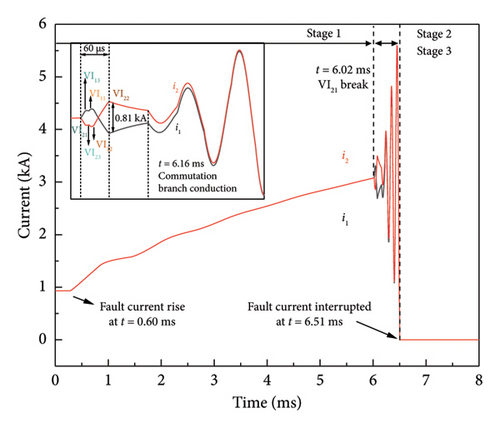
The fault occurs at t = 0 ms, and the line current rises consequently. The fault current at B42 starts to rise at the instant of t = 0.6 ms, and the two parallel branches are still sharing the current. When VI is triggered to operate, the contacts start to be separated by actuators. Considering the action decentralization, the operation sequence of VIs in this simulation is VI21, VI13, VI23, VI11, VI12, and VI22. First, VI21 is operated at t = 6.02 ms, and the vacuum arc is generated between its contacts, which leads the current transfer to the parallel branch. Therefore, i2 gradually decreases, and i1 gradually increases. After VI13 is operated, a vacuum arc is generated between its contacts, and the arc voltage difference between the two parallel branches leads i1 and i2 to be uniform gradually. Then, VI23 is operated. Due to the arc voltage of the short gaps in series being higher than that of the parallel branch, the current transfer process occurs again, as shown in the fact that i2 continues to decrease and i1 continues to increase. Then, VI11 is operated, and the current sharing between i1 and i2 occurs again based on the previous stage at the instant. After VI12 is operated, all 3 breaks of the branch where VI12 is located are in the arc state. Therefore, the transfer speed of i1 to the parallel branch is accelerated, as shown by the increase of i2 and the decrease of i1. When VI22 is operated, the current sharing occurs for the third time in the two parallel branches. It can be seen that there is a time difference of 80 µs between the latest operated VI23 and the earliest operated VI22. In this process, the absolute value of the maximum difference between the parallel current Δi = 0.81 kA. At t = 6.16 ms, the VSC in the commutation branch of the 160 kV 6-module VARC DCCB with series followed by parallel structure is conducted, and the resulting gradual oscillation current is superimposed inversely on the main branch. Finally, an artificial over-zero point is generated at t = 6.51 ms, and the short current is interrupted.
5.2. Reverse Short-Circuit Current Interruption
As shown in Figure 20, the interruption characteristic of the 160 kV 6-module VARC DCCB with series followed by parallel structure at the negative pole of cable 24 is illustrated.
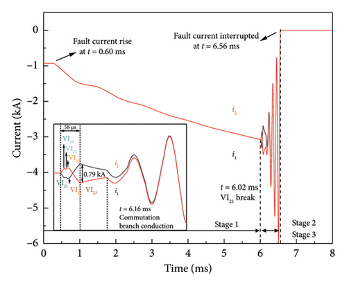
The current through the 160 kV 6-module VARC DCCB before the fault occurs is −1 kA. Similarly, the operating sequence of the 6 VIs when interrupting the reverse short-circuit current is the same as the previous one, except that there is a time difference of 58 µs between the latest operated VI21 and the earliest VI22. In this interruption process, the absolute value of the maximum difference between the parallel current Δi = 0.79 kA. Therefore, the 160 kV 6-module VARC DCCB with series followed by parallel structure is capable of bidirectional DC interruption in this configuration.
6. Conclusions
This paper proposes a VI model suitable for 0–20 kA, which can be used for series-parallel connected multimodule DCCBs for DC interruption, allowing for higher voltage levels and larger-capacity applications. The DC interruption transient characteristics of two types of 160 kV 6-module VARC DCCB with this model are compared and analyzed regarding operating reliability, interruption performance, energy absorption, and costs. The 160 kV 6-module VARC DCCB with series followed by parallel structure shows better performance. The following conclusions can be drawn from the abovementioned results.
The parallel current simulation results of the developed VI model are compared with the experimental data, and the current waveforms obtained from the simulation are in good agreement with the experimental results.
By connecting VIs in series and parallel, DCCB with higher voltage levels and larger interruption capacity can be realized. The 160 kV 6-module VARC DCCB with series followed by parallel structure has a higher reliability of 99.978%. It is less affected by the actuator decentralization, as shown by the absolute value of the maximum difference between the parallel current Δi lying in the smaller range of 0–2 kA, accounting for 66% of the 50 repetitive simulations.
The short-circuit and reverse short-circuit current interruption characteristics of the 160 kV 6-module VARC DCCB with series followed by parallel structure are verified in the ±160 kV 4-terminal MTDC system. The results show that the 160 kV 6-module VARC DCCB with this structure is capable of bidirectional current interruption and applies to MTDC systems.
Conflicts of Interest
The authors declare no conflicts of interest.
Funding
This work was supported by the National Natural Science Foundation Project of China (grant numbers 52107166 and U22B20121), the National Key Research and Development Program of China (grant number 2022YFB2403702), the China Southern Power Grid Technology Project (grant number 030000KC22120008), and the China Postdoctoral Science Foundation (grant number BX20200263).
Open Research
Data Availability Statement
The data that support the findings of this study are available from the corresponding author upon reasonable request.


