Enhanced Power Generation Through Hybrid Solar Chimney Coupled With a Steam Turbine Power Plant Leveraging Heat Recovery
Abstract
The incorporation of solar chimneys and fossil fuel power plants plays a beneficial role in reducing fuel consumption and environmental pollution. The need to pay attention to the turbine placement and the advantage of waste heat recovery from energy resources also increased the importance of the issue. In this study, the potential of integrating waste heat resources of a steam power plant is explored to increase the overall efficiency of a solar chimney power plant (SCPP). The effects of utilizing expelled heat from wet cooling towers and stack’s flue gas are taken as waste resources and are numerically studied on preheating the inlet air of the collector of the SCPP. The influences of designing the proper geometry of the flue gas chimney inside the collector are studied on the air entering the main chimney of the SCPP and the height of the flue gas chimney on the output power. The impact of allocating the semitransparent walls for flue gas chimney is analyzed on the gas temperature and the overall efficiency of the SCPP. Three-dimensional numerical simulations are adopted to contribute to a direct reduction in water consumption in wet condensers and an indirect reduction in fuel consumption of the steam turbine power plant. Based on numerical results, the proper vertical position of the turbine showed the pronounced effect on the output power of the SCPP. The choice of adding simultaneously radiators and flue gas chimney on the output power of the SCPP has become more important than that achieved by the addition of only radiators in all flue gas chimney heights. Ultimately, identifying the best turbine position and the most effective flue gas chimney height led to a 214.1% increase in the overall efficiency of the hybrid SCPP compared to the conventional Manzanares SCPP.
1. Introduction
Extensive efforts are underway to enhance efficiency and reduce pollutant emissions of fossil fuel power plants because of the low efficiency and environmental pollution [1, 2]. Technological advancements have increased the demand for energy consumption, resulting in a greater need for electricity generation [3, 4]. Thermal losses are one of the most influential parameters that reduce the efficiency of fossil fuel power plants. Thermal losses due to the heat dissipation section and the high temperature of the flue gas from the plant’s stack are two significant parameters in reducing the efficiency of fossil fuel power plants [5, 6]. The valuable thermal energy lost is not sufficiently recovered in fossil fuel power plants, leading to consistently high fuel consumption levels.
Considerable efforts are being made to utilize the wasted heat of steam power plants. Attempts are made to harness the thermal energy of hot flue gas, yet the exhaust gas still exists at a notably high temperature. Additionally, both evaporative and natural draft dry cooling towers of steam power plants lose significant thermal energy [7]. Evaporative cooling towers led to waste a substantial amount of water besides losing heat, resulting in the adoption of natural draft dry cooling towers in water-scarce regions [8]. However, dry towers have high capital costs, wasted heat, and reduce the efficiency of the steam power plant [9]. A solar chimney power plant (SCPP) can be used instead of evaporative and natural draft dry cooling towers to solve water and heat loss challenges. SCPP increases the efficiency of the steam power plant by generating electricity. In contrast, the SCPP is still a developing technology because of the low efficiency and high capital cost. The conventional Manzanares SCPP, Spain, has an overall efficiency of about 0.16%, highlighting the critical need for efficiency enhancement [10, 11].
The geometrical changes in SCPP, such as reducing the inlet size of the collector [12], increasing or decreasing the radius and height of the chimney [13, 14], modifying the configuration of the absorber surface [15], and adjusting the divergence angles of chimneys can be utilized to enhance the efficiency of the SCPP [16]. The overall efficiency remains significantly low, despite slight enhancements from geometrical modifications to the SCPP. Additionally, the efficiency improvement is achieved by incorporating various materials and equipment, such as phase change materials, to further enhance the efficiency of the SCPP [17]. Utilizing other technologies, such as filter installation to purify the incoming air [18], spraying water on the incoming air [19], and the role of electrohydrodynamic interactions is also beneficial [20]. The other routes to enhance the power production capacity of the SCPP are recognized by adding a bank of transparent baffles at the entrance of transparent cover [21], utilizing wind-resistant structures [22], counter-wind configurations [23], and solid oxide fuel cells [24]. Despite extensive studies, the SCPP remains an evolving technology with low overall efficiency and high capital costs.
A combined solar chimney–geothermal power plant is recognized as an effective route to enhance the efficiency of the SCPP [25, 26]. Hybrid solar chimney–geothermal power plants could generate electricity during the night and improve the efficiency of the SCPP by 26% [27, 28]. A hybrid geothermal power plant, operating at 75°C, with a SCPP led to a 585.1% improvement in efficiency compared to a standalone geothermal plant [29]. The scarcity of geothermal resources necessitates finding the substitutional resources to integrate with the SCPP technology, despite significant advancements in combining geothermal-SCPPs.
Extensive research has been conducted on combining solar chimney–photovoltaic power plants (SCPVPPs) due to the higher availability of solar energy resources compared to the geothermal [30, 31]. SCPVPP achieves a 4.8% increase in the efficiency of the hybrid system [32]. By positioning photovoltaic panels in a SCPVPP so that the airflow cools the panels, the overall efficiency of the hybrid plant is increased by 29% [33]. Proper placement of photovoltaic panels in a SCPVPP enhances the system’s efficiency. Significant efficiency improvements are achieved by positioning the photovoltaic panels over 80% of the collector area away from the chimney axis [34]. Additionally, an air filtration system incorporated at the air inlet by placing the photovoltaic modules at the bottom of the collector increased the air mass flow rate by 2.42 times [35].
The efficiency of the SCPVPP is tripled by placing photovoltaic panels at the base and modifying the geometry of the inlet of the SCPP to a bell shape [36]. The comparison of two previous studies underscores the necessity of determining the optimal placement for photovoltaic panels in a SCPVPP. Additionally, simultaneous water purification is achieved which results in an output power of 261 kW in a SCPVPP [37]. A SCPVPP is also used as the canopy cover of a greenhouse to harness simultaneously electricity and hot air for domestic heating with air source heat pumps [38]. SCPVPP is hindered by low overall efficiency and the inability to generate electricity continuously.
Continuous waste heat resources are utilized to compensate for the low efficiency of the hybrid system. The waste heat is generated in various sections of the industrial units, which is harnessed to preheat the air inside a solar chimney collector, thereby enhancing the efficiency of the SCPP [39, 40]. The output power of the SCPP is boosted by around 23.1% by utilizing waste heat resources [41]. Combining a heat source with the SCPP enables uninterrupted electricity generation, effectively resolving the challenge of noncontinuous power production in SCPP systems [42]. Refinery flare gas is used as the heat source to improve the output power of the SCPP from 50 to 788 kW [43]. It is possible to increase the efficiency of the nuclear power plant from 35.3% to 42% by utilizing the waste heat in a combined SCPP system [44]. A significant improvement in the efficiency of a SCPP is only achieved where the waste heat from industries is substantial. To address the challenge of low efficiency and access to significant heat sources, it is better to focus on power plants with low efficiency and high waste heat sources.
Fossil fuel power plants generally exhibit low overall efficiency, leading to significant waste heat sources. Integration of a fossil fuel with a SCPP enhances the hybrid system [45]. A gas turbine, as a low-efficiency fossil fuel power plant, is a suitable option for integration with a SCPP. The flue gases from the gas turbine, serving as a waste heat source, are used to preheat the air inside the SCPP [46]. The output power of the hybrid SCPP is improved from 50 to 500 kW by directly introducing the flue gases from the gas turbine into the inlet and midsection of the collector [47].
Similarly, the waste heat from a steam power plant is harnessed to boost the efficiency of a SCPP by 0.37% [48]. The heat expelled from condensers and the flue gases from the power plant’s chimney is utilized to achieve an efficiency improvement of 0.538% [49]. Given the relatively modest efficiency improvements from integrating the SCPP with the steam power plant, there is a clear need for further design innovations to effectively harness the waste heat from the steam power plant and enhance the efficiency of SCPP. Despite the benefits of the integrated SCPP with the steam power plant, including reduced water consumption and conservation of fuel, additional research is required to attain higher efficiency levels of the hybrid system. Table 1 shows the comparison of hybrid SCPP with other renewable energy technologies. As can be seen, the SCPP shows a compelling economic justification compared to other renewable energy sources due to its relatively low maintenance costs and long operational lifespan [52]. While its initial installation cost (€1.2–€3.5 million per MW) may be higher than solar PV (€0.5–€1 million per MW) or wind (€1–€1.5 million per MW), its ability to generate a stable energy output power, even in low sunlight conditions [53]. Additionally, SCPP avoids the need for expensive storage solutions like batteries, which are critical for intermittent sources such as solar PV and wind [54]. An estimated levelized cost of energy (LCOE) ranging between €50 and €120 per MWh showed that the SCPP remains competitive with traditional renewables, particularly in regions with high solar irradiance [55]. These economic advantages, coupled with their minimal environmental impact and suitability for arid regions, make solar chimney an attractive option for sustainable energy generation.
| Metric | Hybrid SCPP | PVa | Wind turbines | CSPb |
|---|---|---|---|---|
| Energy conversion efficiency | 1%–2% (can be improved in hybrid configurations with thermal storage) [39] | 15%–22% (reaching up to 25% for commercial PV panels [32] | 30%–50% (depending on wind speed and turbine design) [50] | 20%–35% (depending on the technology and thermal storage integration) [51] |
| Land use | High (due to large required collector area) [11] | Moderate [38] | Moderate [50] | High (due to the need required for mirrors or lenses) [51] |
| Cost-effectiveness | Moderate to high initial capital cost, low operational, and maintenance costs [11] | Moderate initial cost (depending on technological advancements) [35] | High initial cost (competitive in windy regions) [50] | High initial cost (can be improved over time by thermal storage) [51] |
| Environmental impact | Low impact; no emissions during operation (suitable for arid regions) [10] | Low impact (panel production issues) [36] | Low impact, but concerns about bird and bat mortality [50] | Low impact (water consumption for cooling system can be issues) [51] |
| Energy storage | Built-in thermal storage allows continuous operation (day and night) [37] | Requires external battery storage for continuous power supply [37] | Requires external storage or grid integration [50] | Integrated thermal storage allows for continuous operation [51] |
| Scalability | For large-scale applications in arid or semi-arid regions [10] | Highly scalable (small rooftop installations to large solar farms) [32] | Scalable (limited to regions with wind resources) [50] | Scalable (best suited for regions with high direct solar irradiance) [51] |
| Maintenance | Low (due to simple design and lack of moving parts) [11] | Moderate (for cleaning panels and replacing inverters) [34] | High (due to mechanical wear and moving parts) [50] | Moderate to high (especially for mirror alignment) [51] |
- aConcentrated solar power.
- bPhotovoltaic systems.
- 1.
The impact of using the waste heat recovery from the steam power plant’s condenser water to preheat the air entering the collector of the SCPP on the hybrid system’s output power.
- 2.
The influence of simultaneous utilization of the waste heat from both the condenser water and the flue gas in a steam power plant on the overall efficiency.
- 3.
The significance of designing the proper geometry of the flue gas chimney depends on the temperature of the air inside the collector of the SCPP.
- 4.
The effect of the height of the flue gas chimney on efficiency enhancement.
- 5.
Allocating the semitransparent walls for flue gas chimney on the improving gas vacuum pressure at the vertical position of the SCCP’s turbine.
To address all of the mentioned points on decision-making for design parameters, the present work is undertaken. The effect of adding condenser water heat exchanger and semitransparent flue gas chimney design and height (of various heights 3–50 m) on the performance of an SCPP is assessed by adopting the power generation and overall efficiency analyses. The present work explores the effects of adding waste heat sources of an actual steam power plant in a new design on SCPP performance by analyzing three-dimensional turbulent flow computational fluid dynamics (CFD) approach. The present work contributes to developing sustainable energy technologies vital for modern society. Its original findings could inspire future research, particularly in hybrid solar chimney–steam power plants, offering a promising avenue for sustainable energy production.
2. Mathematical Model
2.1. Geometrical Scheme Specifications
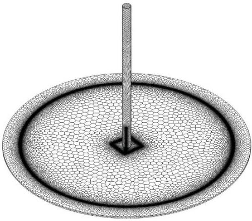
Figure 1a,b shows the schematic diagram of the geometrical model and the volume meshing structure of the hybrid SCPP model. The considered dimensions closely resemble the initial Spanish Manzanares SCPP design [56]. The condenser water is introduced through radiators situated at the entrance of the SCPP collector. Radiators are designed as finned-coil heat exchangers, occupying 50% of the collector’s entrance area [57]. The flue gas emitted from the steam power plant’s stack enters the flue gas (inlet 2), travels through a square pipeline, and then proceeds into a flue gas chimney, eventually blends with the ambient air from the main chimney. Ambient air is entered through the airflow (inlet 1).
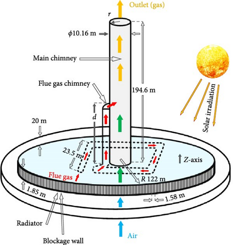
Initially, it undergoes heat exchange with the incoming radiators and is preheated. In the collector area, the inlet air is preheated by capturing solar radiation and undergoing the greenhouse effect. It then reaches the pipes containing hot flue gas, where it undergoes the final heat exchange. The heated air enters the main chimney, moving toward the outlet and generating power in the turbine at the base of the chimney tower. The base of the chimney is a hypothetical plane positioned at a specific height, which will be discussed further regarding its elevation and location.
The geometrical structure of the flue gas chimney pipes positioned in the collector area of the SCPP is a crucial design factor. Pipes are designed in a roughly square shape with side edges of 23.5 m in the present work. Expanding the pipe surface area improves heat transfer between the flue gas and the flowing air, but it will lead to two economic challenges. First, as heat is transferred, flue gas temperature drops, necessitating a taller flue gas chimney for effective reheating under sunlight before entering the main chimney; this increase in height raises initial construction costs for the SCPP. Second, longer internal pipes increase material requirements and higher initial expenses. Thus, there is a pressing need to optimize between rising costs and enhanced output power, which is a worthy subject of further investigation. Figure 1b shows the polyhedral meshing method that is used for reducing cell number and improving meshing quality which improves solution accuracy and reduces computation time.
2.2. Assumptions and Boundary Conditions (BCs)
- 1.
Three-dimensional steady-state fluid flow is modeled.
- 2.
Air and flue gas (with Pr = 0.71) are presumed to be Newtonian, turbulent, and with constant thermophysical properties. The Boussinesq approximation is considered valid for modeling gas density as [56]:
- 1.
Fin tube heat exchangers are modeled as internal walls within the radiator model, occupying 50% of the collector’s entrance area.
- 2.
The solar radiative power level is considered to be 1000 W m−2. In this study, we only focused on the influences of designing the proper geometry of the flue gas chimney inside the collector. Therefore, the results of lower irradiance levels are not presented because of the simplicity of the results and discussion. It should be noted that the power generation of solar chimneys increases with an increase in the solar radiation level and the amount of electrical power produced by the system also increases during months with higher solar radiation, particularly from March to September [54].
- 3.
The simulating location has latitude equal to 38.99 °N, longitude equal to 3.37 °W. Fair weather conditions (on May 21, 2024 at 1 PM) are considered.
- 4.
Ambient air density and temperature are considered 1.225 kg m−3 and 302 K.
- 5.
The turbine and generator are not modeled directly [58].
- 6.
The following BCs are applied in the simulation model:
- a.
A hypothetical base plane is considered in the simulations to represent the vertical position of the turbine, where the maximum extractable power is achieved in the results.
- b.
The ground wall is made of ground material with opaque and adiabatic BCs.
- c.
The collector and flue gas chimney walls are made of semitransparent glass, receiving a whole irradiation of 1 kW m−2.
- d.
A convective thermal BC with hg = 10 W m−2K−1 is applied to these semitransparent walls. All other walls are made of aluminum with opaque and adiabatic BCs.
- e.
Ambient air enters at the inlet 1 with an inlet pressure of one atmosphere.
- f.
Flue gas enters inlet 2 with a mass flow rate of 80.7 kg s−1 at 400 K [49].
- g.
The outlet gas exits through the main chimney with an outlet pressure of one atmosphere.
- h.
The condenser water flows into the finned-coil heat exchangers at 333.15 K [49].
- a.
2.3. Governing Equations and Related Parameters
Equations (12) and (13) offer suitable approximations for the condenser water heat exchangers within the radiator model, simplifying the SCPP modeling [57].
2.4. Fluid and Solid Properties
For modeling simplification, the same properties have been considered for flue gas and air, which are itemized in Table 2. As mentioned, gas density is calculated using the Boussinesq formulation in Equation (1). Three solid materials were considered for modeling the solid parts including aluminum, ground, and glass. The main properties of these solid materials are listed in Table 3.
| Property | (J kg−1 K−1) | μg (kg m−1 s−1) | kg (W m−1.K−1) | βg (K−1) |
|---|---|---|---|---|
| Value | 1006.43 | 0.0000179 | 0.0242 | 0.00331 |
| Solid material | ρs (kg m−3) | (J kg−1 K−1) | ks (W m−1 K−1) | λ (m−1) | n |
|---|---|---|---|---|---|
| Aluminum | 2719 | 710 | 1.83 | 0 | 1 |
| Ground | 2160 | 871 | 202.4 | 0.9 | 1 |
| Glass | 2500 | 750 | 1.15 | 0.03 | 1.516 |
2.5. Methodology and Simulation Procedure
Three different configurations analyzed include a standard solar chimney power plant (SSCPP), solar chimney power plant with radiators (SCPPRs), and solar chimney power plant with radiators and flue gas chimney (SCPPRFC). The objective is to assess the effect of incorporating radiators and a flue gas chimney on the output power and overall efficiency of the SCPP. To evaluate the influence of the flue gas chimney height on the power generation of the combined SCPP, different heights (d) ranging from 3 to 50 m are simulated. In each scenario, the turbine’s placement is determined by identifying the vertical height of the base plane along the main chimney’s vertical axis. The base plane is positioned where it achieves the maximum power generation capacity. Additionally, the flue gas chimney must be elevated above the base plane to ensure the flue gas does not come into contact with the turbine blades.
CFD simulations approach was carried out using commercial ANSYS Fluent 2023R2. The pressure-based solver utilizing the Coupled algorithm was chosen for the pressure–velocity coupling scheme, and the spatial discretization method for pressure employed a PRESTO algorithm. Also, second-order upwind was used as a discretization scheme for momentum, turbulent kinetic energy, dissipation rate, and discrete ordinates. The continuity equation maximum residual of 10−6 is chosen for convergence criteria. The computational simulations were carried out on a computer system with an Intel Core i7 processor running at a clock speed of 1.30 GHz and 16 GB of memory (RAM). It took ~8 h to simulate each SCPP model with the whole capacity as four processing cores in parallel order.
2.6. Grid Independency Test
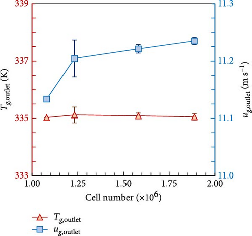
Figure 2 shows the grid independency test results by testing a different number of cells. The outlet gas temperature and outlet gas velocity of the main chimney are chosen for grid independence analysis criteria. Four various grids, comprising 1,080,031, 1,231,514, 1,580,828, and 1,887,125 cells, were utilized to study grid independence. As the cell number escalated from 1,080,031 to 1,231,541, the outlet gas temperature and velocity from the main chimney changed by ~0.03% and 0.6%, respectively. Outlet gas temperature and velocity changes consistently decreased with further increases in cell number. Finally, the changes in the outlet gas temperature and velocity from the main chimney by growing the cell number from 1,580,828 to 1,887,125 were ~0.01% and 0.12%, respectively. Therefore, the results show achieving the grid independence at a cell number of 1,580,828.
3. Results and Discussion
To achieve the accuracy of the suggested model, the results are validated first by the experimental data reported by Mandal et al. [56] and Mokhtari Shahdost [46], and then the numerical results of the hybrid SCPP are discussed.
3.1. Validation of the Numerical Model
Figure 3a,b shows the simulation results of the gas pressure and gas velocity of the base plane along the radial distance of the main chimney, respectively. The SSCPP is selected for validating the simulation settings. Gas pressure and velocity at the base plane are chosen as criteria for the simulation results validation due to their direct impact on computing the generated power of SCPP. The overestimation of gas pressure data with an average of 1.92% and the underestimation of gas velocity with an average of 3.65% exist on the base plane of the main chimney between the present work and Mandal et al. [56], respectively. Analysis of the error bars indicates that the highest errors in gas pressure and velocity at the base plane of the SCPP occur near the main chimney wall, which may arise from differences in the wall function models used in the simulations. Validation results show a consistent overall trend between the gas pressure and velocity in the present work and the findings in Mendel et al. [56] indicating that the current CFD is suitable for investigating SCPP.
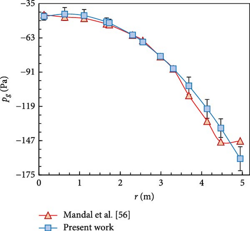
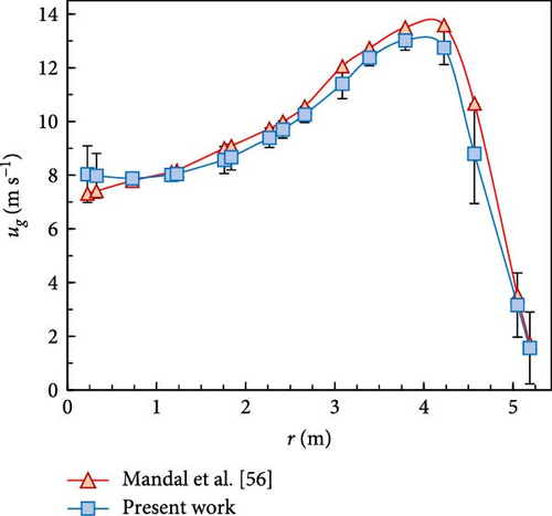
Figure 4a shows the numerical model results of the inlet velocity of ambient air, ua,inlet, versus (Figure 4a) outlet gas temperature, and (Figure 4b) outlet gas velocity. The validation of the results of the present study was performed based on the experimental data obtained from a SCPP system integrated with an exhaust gas wasted from a heat source [46]. The air is modeled instead of simulating exhaust gas, due to the similar thermophysical properties of the two fluids. Moreover, the thermophysical properties of the air are considered to be constant, while the density function is based on the Boussinesq approximation. A good trend with a maximum acceptable error of 7.8% supports the validity of the numerical modeling, despite all the simplified assumptions and existing errors.

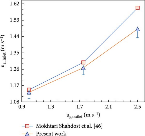
The discrepancy between the experimental and numerical results can be attributed to the uncertainty of data in measurement of the velocity and temperature of the exhaust gas, and nonuniformity in the intensity of solar irradiation in the real conditions [46]. The simplifying assumptions of considering constant thermophysical properties of the air and modeling the air instead of the exhaust gas also influence a minimal discrepancy between the experimental data and numerical results.
Table 4 shows the validation of our numerical results by the available experimental data reported for the SSCPP system. The output power, upwind velocity, and temperature rise are chosen as criteria for the simulation results. The upwind velocity and temperature rise are the gas velocity at z = 10m and the gas temperature difference between collector inlet and outlet (at r = 10m), respectively. The low relative error between the results indicates a good agreement between the numerical results of the present study and the experimental data reported by Haaf et al. [54]. The main reason for the deviation between the results of the present study and the experiment data lies in the absence of modeling of the curvature part of the connection region between the collector and chimney, which significantly influences the numerical results obtained from the SSCPP.
| Study | Approach | Upwind velocity (m s−1) | Error (%) | Temperature rise (K) | Error (%) | P(kW) | Error (%) |
|---|---|---|---|---|---|---|---|
| Haaf et al. [54] | Experimental | 15 | — | 20 | — | 50 | — |
| Schlaich et al. [52] | Experimental | — | — | — | — | 41.97 | 16.6 |
| Present work | Numerical | 14.79 | 1.4a | 19.38 | 3.1a | 49.41 | 1.18a |
- aThe relative errors were calculated through the difference between the numerical results and experimental data reported by Haaf et al. [54].
3.2. Application of the Validated Model
3.2.1. Effect of Adding Radiators
Figure 5 shows the effects of incorporating radiators from a steam power plant into the SSCPP on gas vacuum pressure and gas velocity variation across the vertical height of the main chimney. Figure 5a shows that both the SSCPP and SCPPR show a similar overall trend in gas vacuum pressure changes through the main chimney. An increase in the vertical height of the main chimney from 1.5 to 7 m shows a steep rise in gas vacuum pressure (increase in negative values) for both configurations, with the gradient being sharper for the SCPPR than the SSCPP. The gas vacuum pressure difference between the SSCPP and SCPPR at the entrance of the main chimney is ~36.3 Pa which is reached at 159.2 Pa at the vertical height of 7 m. The gas vacuum pressure changes in both SSCPP and SCPPR in the range of 7–9 m becomes gradual. The gas vacuum pressure decreases by increasing the vertical height from 9 m to the outlet of the main chimney to reach atmospheric pressure eventually. Consequently, the region with a vertical height of 7–9 m is proper for turbine installation based on the gas vacuum pressure analysis. However, a closer examination reveals that the highest gas vacuum pressure in both the SSCPP and SCPPR occurs precisely at the vertical height of 8 m. The maximum gas vacuum pressure in the SSCPP and SCPPR are −178.3 and −340.2 Pa, respectively. The observed maximum gas vacuum pressure values at vertical height of 8 m differ slightly from the values at vertical height of 7 m, confirming the gradual changes in the range of 7–9 m.
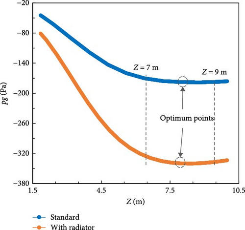
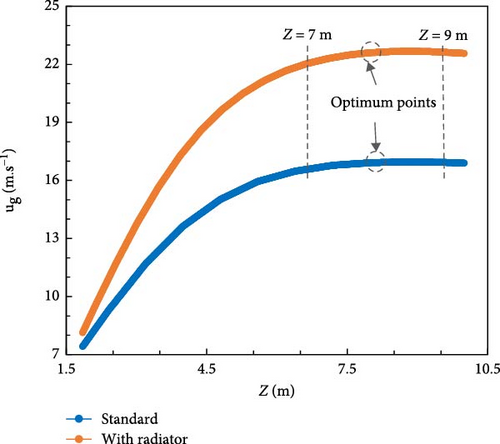
Figure 5b shows the gas velocity relative to the vertical height within the main chimney, which illustrates a similar trend between the gas velocity in the SSCPP and SCPPR, consistent with the gas vacuum pressure. The gas velocities at the entrance of the main chimney are similar for SSCPP and SCPPR, being 7.4 and 8.1 m s−1, respectively. A relatively steep increase in the gas velocity exists with an increase in the vertical height within the main chimney up to 7 m, reaching 16.7 and 22.2 m s−1 for the SSCPP and the SCPPR, respectively. The gas velocity trend for SSCPP and SCPPR configurations becomes very gradual in the vertical height range of 7–9 m. The gas velocity decreases beyond 9 m to the chimney outlet. Therefore, similar to the gas vacuum pressure analysis, the vertical height range of 7–9 m is suitable for turbine installation.
The most gas velocity for both the SSCPP and SCPPR occurs at 8 m with maximum gas velocities of 17 and 22.7 m s−1 for the SSCPP and SCPPR, respectively. Consequently, the proper vertical position for installing the turbine for both SSCPP and SCPPR configurations, which promise the highest power output, is determined at a vertical height of 8 m by analyzing the gas vacuum pressure and gas velocity simultaneously. Therefore, incorporating radiators into the SSCPP would not alter the appropriate vertical position of the base plane, while affecting the gas vacuum pressure and gas velocity quantities. Positioning the base plane at an elevation of 8 m, as opposed to the 1.85 m used in Mandal et al. [56], has led to a 54% increase in generated power, underscoring the importance of accurately placing the base plane.
Figure 6 shows the temperature contour plots of a front view of the two configurations of SSCPP and SCPPR. The ambient air, entering at a temperature of 302 K, is directed into the collector of the SCPP. The air temperature at the collector’s entrance is increased by 20 K upon integrating radiators into the SSCPP. The preheating process caused by adding radiators results in a decrease in air density and a corresponding increase in buoyancy force, as outlined by Equation (1). The radiators’ preheating effect causes a more uneven distribution of temperature gradient within the collector area of the SCPPR, as opposed to the SSCPP configuration. Consequently, a more significant intensified natural convection effect is shown in the collector area of the SCPPR compared to the SSCPP configuration. The addition of radiators further enhances the temperature gradient at the turbine installation position.
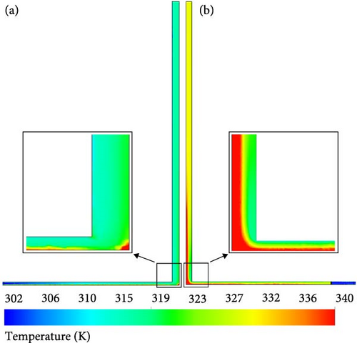
The average temperature at the base plane in the SSCPP stands at 316.4 K, which climbs to 326.7 K in the SCPPR configuration. As the gas in the main chimney of the SCPP moves past the base plane and heads toward the outlet of the main chimney, the temperature gradient decreases, and the gas temperature approaches a stable state toward the constant values. The temperature stabilization occurs at higher elevations in the SCPPR compared to the SSCPP configuration.
3.2.2. Effect of Adding Flue Gas Chimney
Figure 7 shows the effects of incorporating condenser radiators and a flue gas chimney of the steam turbine power plant simultaneously into the SSCPP on gas vacuum pressure and gas velocity variation along the vertical height of the main chimney at different flue gas chimney heights. Figure 7a shows the impact of using flue gas chimneys of varying heights on the gas vacuum pressure in a SCPPR, showing a relatively similar trend across all configurations. The results showed an initial rise in gas vacuum pressure for all samples as the distance from the main chimney entrance increased. An increase in gas vacuum pressure due to height increment along the main chimney begins with a very steep slope, which gradually decreases over time. The optimal point with the highest gas vacuum pressure is reached by reducing the slope of the graph ranging between the height of 6 and 10 m. The highest gas vacuum pressure for configurations with 3 and 5 m flue gas chimneys occurs at a main chimney height of 10 m. In contrast, for configurations with flue gas chimney heights ranging from 10 to 50 m, the maximum gas vacuum pressure occurs at 7 m. The difference in the maximum gas vacuum pressure position underscores the significance of performing individual analyses for each configuration to fully leverage the maximum vacuum capacity generated which is not explored in the prior research. The gas vacuum pressure decreases in all configurations until it eventually reaches the atmospheric pressure at the outlet of the main chimney with a further increase in height of the main chimney, which shows that the higher altitudes are unsuitable for turbine installation.
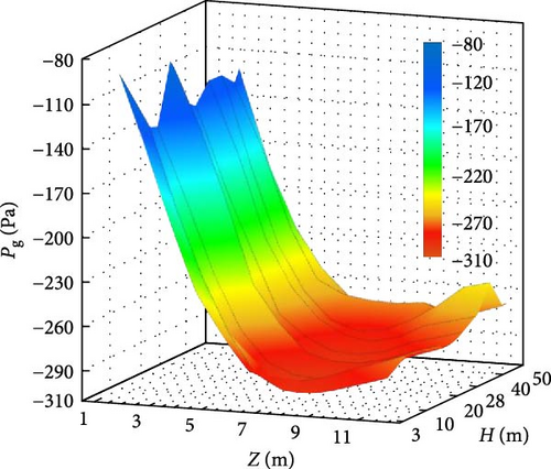
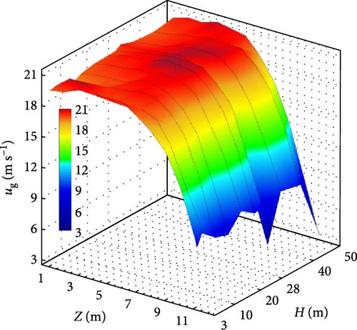
Figure 7b shows the impact of utilizing the flue gas chimney at different heights on the gas velocity inside the main chimney of a SCPPR. The gas velocity increases within a steep slope by increasing the height of the main chimney, followed by a decrease within the range of 6–10 m. Further height increments reduce the gas velocity, forming a maximum velocity point inside the main chimney. The maximum gas velocity points occur at the height of 10 m for SCPP with the flue gas chimney height of 3 and 5 m, while the height of 7 m is the optimum position for the SSCPP with 10–50 m flue gas chimney. The optimum positions where the maximum gas velocity and gas vacuum pressure coincide are crucial for achieving the highest power output in the hybrid SCPP, determining the turbine placement. However, placing turbines at the vertical position of 10 m for the SCPP configurations with the flue gas chimney having 3 and 5 m height risks the mixing of the flue gas with the incoming air in the main chimney, potentially damaging the turbines for an extended period. Consequently, turbines of the SCPP with the flue gas chimney height of 3 and 5 m are installed at the height of 2.5 and 4.5 m, respectively, because of the initial steep rise in the gas vacuum pressure and gas velocity at the entrance of the main chimney. Analyzing gas vacuum pressure and gas velocity across various chimney heights ensures reaching the optimum power output which has been less explored in the previous studies [27, 61, 62].
Figure 8 shows the gas velocity vectors for SCPPRFC with a height of 20 m. The results showed that the increase in air velocity inside the collector of the SCPPRFC is significantly higher when passing through the horizontal section of the flue gas chimney compared to passing through the radiators and internal area of the collector. Furthermore, the regions below the glue gas entry region from the flue gas chimney into the main chimney show higher velocities than the upper sections of the main chimney, possibly due to the vacuum pressure generated by the upward movement of the flue gas. No reverse flow or vortex region was detected when the air entered the main chimney, preserving the buoyancy force and air natural convection. The flue gas in the flue gas chimney, after entering the main chimney of the SCPP and covering a short horizontal distance, moves ultimately upward, ensuring no formation of vortices and allowing the gas to move upward unhindered. The absence of vortices at the entrance area where flue gas enters the main chimney from the flue gas chimney has been confirmed in all configurations, to ensure no impedimentum to the upward gas movement.
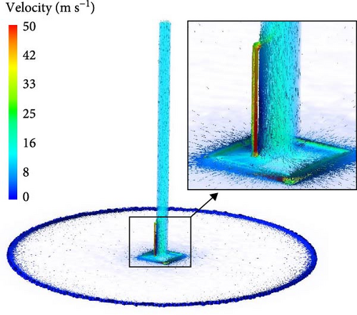
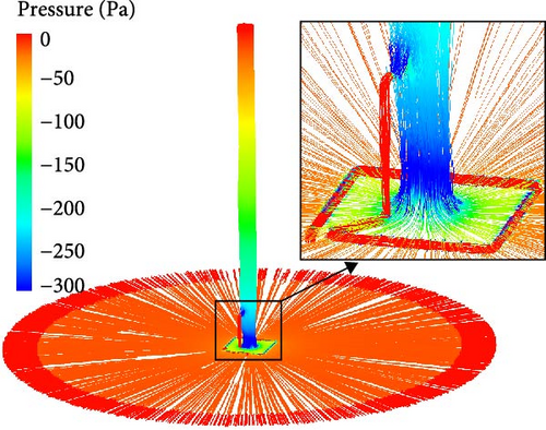
Figure 9 shows the streamlines colored based on gas vacuum pressure for SCPPRFC with a height of 20 m. The streamline indicates that the inlet air throughout the collector, along with the gas inside the main chimney, all show negative pressure values, signifying the natural vacuum occurring in all areas of the SCPP. Additionally, the results show that the gas vacuum pressure exhibits a more excellent enhancement when the gas flows through the horizontal section of the flue gas chimney compared to the passing through the radiators. A comparison of the effects of adding radiators and the flue gas chimney into the collector of the SSCPP shows that the flue gas chimney has a more pronounced influence on both elevating gas vacuum pressure and increasing gas velocity. Therefore, the flue gas chimney has a more significant role in boosting the output power of the SSCPP than the radiators. The areas positioned below the entrance area of the flue gas to the flue gas chimney show the highest vacuum pressure throughout the entire main chimney, which is appropriate for turbine installation.
3.2.3. Comparison of Overall Efficiency and Generated Power
Figure 10 compares the effect of utilizing different configurations including SSCPP, SCPPR, and SCPPRFC with the height of 3 m on the generated power and overall efficiency. The integration of radiators into the SSCPP has induced an upsurge in the generated power and overall efficiency by 57.2%, highlighting the beneficial effects of adding radiators. The output power is increased 142.2% by adding radiators to the SSCPP with the turbine positioned at the vertical height of 1.85 m. The analysis of the results highlights how crucial the appropriate turbine placement is in improving power output, allowing the full exploitation of potential power generation. Furthermore, incorporating radiators into the SSCPP and positioning the turbine at the proper elevation considerably increase the power output by simultaneously recovering the waste heat from the radiators. Furthermore, the simultaneous integration of radiators and a flue gas chimney with a height of 3 m into the SSCPP leads to a 93.5% increase in output power and overall efficiency compared to the SSCPP. Likewise, assessing the efficiency gain from the combined addition of radiators and a flue gas chimney against the SSCPP with the base plane positioned at the height of 1.85 m results in a 198% increase in the output power and the overall efficiency. Substantial efficiency enhancements have been achieved by integrating both radiators and a flue gas chimney into the SSCPP which was an unexplored approach in previous research.
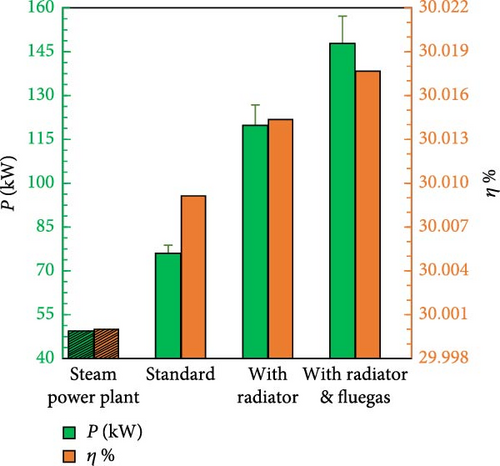
Figure 11 shows the effect of adding a flue gas chimney of different heights into the SCPPR on the generated power and overall efficiency. There is no strict upward or downward trend between the increase in flue gas chimney height and the output power and efficiency of the SCPP. The absence of a strict trend with increasing flue gas chimney height may be due to the presence of two opposing factors that one of which increases the efficiency while the other decreases it. The surface area of the transparent walls exposed to sunlight, which leads to more heat being absorbed by the flue gas, is increasing by increasing the height of the flue gas chimney. However, increasing the height of the flue gas chimney causes the flue gas to enter the main chimney at a farther distance from the base plane, which reduces the gas vacuum pressure generated in the base plane’s hypothetical position. Therefore, the appropriate height for the flue gas chimney will be possible through simulation results and cannot be predicted in advance. The maximum generated power and overall efficiency of the hybrid SCPP is recorded at a flue gas chimney height of 28 m, yielding 155.2 kW and 0.333%, respectively.
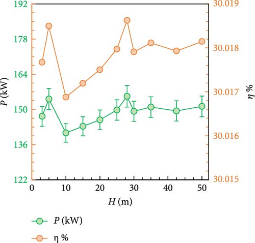
The SCPPRFC configuration with a height of 28 m results in an efficiency increase of 29.7% over the SCPPR configuration, and an efficiency increase of 214.1% compared to the Manzanares SCPP with the turbine positioned at the conventional height of 1.85 m. The notable improvement realized in the best configuration of the hybrid SCPP is rarely achieved in prior research and constitutes a significant leap in the development of SCPP technology.
It should be noted that the SCPP is regarded as an evolving technology for electricity generation purposes [10, 11, 51]. Therefore, although the efficiency improvement of the SCPP system remains relatively low (0.333% compared to 214.1%), it has demonstrated effective performance in waste heat recovery applications, making a significant contribution to environmental preservation [4]. However, under current conditions, the exclusive use of the SCPP system for electricity generation cannot be justified based on its environmental impact.
4. Conclusions and Outlook
- 1.
The adjustment of turbine at the optimal vertical position of 8 m instead of 1.85 m, used in Manzanares SCPP, affects notably the gas vacuum pressure and gas velocity. The output power of the SSCPP show 54% improvement by positioning the base plane at the height of 8 m instead of 1.85 m which is in the same order as 57.2% improvement caused by adding radiators to the SSCPP.
- 2.
An increase in the height of the flue gas chimney results in a further vertical distance between the inlet flue gas and the base plane, reducing the gas vacuum pressure and gas velocity at the turbine position. Solar radiation absorption improves by allocating a semitransparent flue gas chimney wall, which increases the gas vacuum pressure and gas velocity. The output power of the SCPPRFC shows a nonpredictable trend due to two opposing effects.
- 3.
The addition of the flue gas chimney to the SCPPR at the different heights ranging from 3 to 50 m shows an increase in gas vacuum pressure and gas velocity across all the configurations. The results show that the SCPPRFC configurations have higher overall efficiency and output power.
- 4.
The SCPPRFC configuration with height of 28 m has shown the most efficient model, achieving an output power of 115.2 kW and an overall efficiency of 0.333%. The most efficient configuration shows an efficiency enhancement of 214.1% over the Manzanares SCPP, with the conventional vertical position of the turbine at 1.85 m.
These findings underscore the potential of tailored turbine placement, waste heat recovery, and structural optimizations in significantly enhancing the performance of hybrid SCPP systems.
As an outlook for future studies in this field, the impact of lower irradiance levels can be further analyzed within the model to assess system robustness under less favorable conditions.
Nomenclature
-
- A:
-
- Area, m2
-
- c:
-
- Constant, dimensionless
-
- cp:
-
- Specific heat, J kg−1 K−1
-
- G:
-
- Creation of turbulent kinetic energy, J
-
- :
-
- Gravitational acceleration, m s−2
-
- h:
-
- Heat transfer coefficient, W m−2 K−1
-
- H:
-
- Auxiliary chimney height, m
-
- J:
-
- Diffusion flux, mol m−2 s−1
-
- k:
-
- Thermal conductivity, W m−1 K−1
-
- L:
-
- Loss coefficient, dimensionless
-
- n:
-
- Refractive index, dimensionless
-
- P:
-
- Generated power, W
-
- p:
-
- Pressure, Pa
-
- Q:
-
- Volume flow rate, m3 s−1
-
- q:
-
- Heat, J
-
- r:
-
- Radial distance, m
-
- S:
-
- Source of energy, J
-
- :
-
- Scattering direction, m
-
- T:
-
- Temperature, K
-
- :
-
- Velocity, m s−1
-
- Vp:
-
- Perpendicular airflow, m s−1
-
- Z:
-
- z-axis coordinate, m
Greek Symbols
-
- α:
-
- Inverse effect Prandtl number, dimensionless
-
- β:
-
- Thermal expansion coefficient, K−1
-
- ε:
-
- Dissipation rate, m2 s−3
-
- λ:
-
- Absorption coefficient, m−1
-
- σs:
-
- Scattering coefficient, m−1
-
- κ:
-
- Turbulent kinetic energy, m2 s−2
-
- ρ:
-
- Density, kg m−3
-
- μ:
-
- Dynamic viscosity, kg m−1 s−1
-
- ϖ:
-
- Phase function, rad
-
- Ω’:
-
- Solid angle, sr
-
- η:
-
- Efficiency, %
Subscripts
-
- a:
-
- Ambient
-
- coll:
-
- Collector
-
- eff:
-
- Effective
-
- g:
-
- Gas
-
- h:
-
- Heat
-
- i:
-
- Inlet
-
- Outlet:
-
- Outlet
-
- s:
-
- Solid
-
- t:
-
- Turbine
-
- w:
-
- Water
Abbreviations
-
- BC:
-
- Boundary condition
-
- CFD:
-
- Computational fluid dynamics
-
- Pr:
-
- Prandtl number
-
- SCPP:
-
- Solar chimney power plant
-
- SCPPR:
-
- Solar chimney power plant with radiators
-
- SCPPRFC:
-
- Solar chimney power plant with radiators and flue gas chimney
-
- SCPVPP:
-
- Solar chimney photovoltaic power plant
-
- SSCPP:
-
- Standard solar chimney power plant
-
- LCOE:
-
- Levelized cost of energy.
Conflicts of Interest
The authors declare no conflicts of interest.
Funding
This work was supported by the Hamedan University of Technology, Chemical Engineering Department (grant numbers 2340, 1402).
Acknowledgments
The author would like to thank the Hamedan University of Technology (grant no. 402/2340).
Open Research
Data Availability Statement
The data that support the findings of this study are available from the corresponding author upon reasonable request.


