Smart Bricks With Phase Change Material Capsules for Green Buildings: A Numerical Simulation Alongside With Techno-Thermo-Economic Evaluation
Abstract
This study explores the role of green building technologies in the development of a sustainable future by evaluating the techno-economic benefits of phase change materials (PCMs) in building walls. The purpose of this research is to investigate how PCMs can be incorporated into bricks to reduce the use of electricity for cooling the building and temperature fluctuations caused by varying indoor temperatures (Ti = 18, 20, 22, and 24°C) and outdoor temperatures (To = 25, 28, 31, and 34°C). An analysis of the thermal and economic behavior of three aluminum cylindrical capsules containing PCM embedded within brick structures is presented using computational fluid dynamics (CFDs) simulations conducted over a period of 12 h in order to determine the interaction between the brick, the PCM capsules, and the buoyant forces. Results indicate that PCM capsules perform optimally within specific temperature ranges, achieving their peak efficacy between 20 and 24°C, while 25–31°C are ideal To values. It is estimated that adoption of PCM-integrated bricks can save you between $414.7k and $444.3k over the course of 30 years. The internal rate of return (IRR) of this system averages 1.583–1.70, which is significantly higher than the discount rate of 0.02, thus highlighting its attractiveness as an investment.
1. Introduction
Green buildings have emerged as a vital solution to the urgent demand for sustainable development within the construction industry. Green buildings are usually defined as sustainable and eco-friendly structures that minimize resource use, reduce pollution, and improve living and working conditions [1–3]. They incorporate innovative strategies, technologies, and materials to optimize energy efficiency [4]. The construction and operation of buildings have significant environmental implications. Most buildings use high energy, leading to CO2 emissions, exhausting natural resources, generating waste, and adversely affecting human health and well-being [5–7]. In contrast, green buildings address these issues holistically, reducing their ecological footprint and improving overall sustainability. The primary objective of green buildings is to enhance their energy performance. They utilize a variety of strategies, including efficient building envelope design and energy-efficient heating, ventilation, and air conditioning (HVAC) systems, to lower energy consumption [8–10]. Additionally, the incorporation of renewable energy technologies, such as solar panels and wind turbines, can produce reliable energy, leading to a reduction in the need for fossil fuels [11]. The integration of phase change materials (PCMs) into building walls can significantly increase energy efficiency. A study conducted in China found that PCM-filled tubes embedded in brick walls reduced heat flux by 42.1% and had an effective utilization rate of 97% when they were spaced 0.01 m apart. Similarly, research in Iran demonstrated that the Enerciel 22 PCM reduced heat transfer by 15.6%–47.6%, depending on the wall configuration. The effective heat capacity model was also used to compare two types of paraffin wax PCMs, demonstrating that the one with a lower melting temperature and higher latent heat capacity was better at storing external heat [12–14].
Furthermore, green buildings emphasize the use of sustainable materials and construction methods. This involves utilizing recycled or locally sourced products, opting for low-emission materials, and adopting strategies to minimize construction waste. Through these practices, green buildings aim to decrease raw materials, extraction reduce waste generation, and support a circular economy [15–17]. Indoor air quality is an important parameter for green buildings. Their design emphasizes ample natural light, effective ventilation systems, and the use of low-toxicity materials to create a healthy and comfortable indoor environment. Furthermore, features such as green roofs, living walls, and urban gardens are often integrated to enhance indoor quality [18–20]. Research indicates that green buildings—characterized by better indoor air quality, abundant natural light, and comfortable thermal conditions—lead to lower absenteeism, improved cognitive function, and enhanced occupant satisfaction [21–23].
As the high need for energy-efficient and sustainable buildings is increasing, researchers and engineers are exploring innovative solutions to decrease energy needs and improve thermal comfort. One approach gaining traction is to employ PCMs in building design and construction [24–26]. PCMs possess the remarkable ability to store and release significant amounts of latent heat during phase transitions, making them a promising option for improving energy efficiency and occupant comfort within buildings. Incorporating PCMs into buildings addresses a number of thermal energy management challenges. Traditional building materials often demonstrate high thermal conductivity, leading to rapid heat transfer and limited thermal storage capacity [27–29]. In contrast, PCMs can absorb heat during phase changes, allowing them to store impulsive thermal energy during peak temperatures. Using this latent heat storage capability, it is possible to moderate temperature variations, decrease the demand for active heating or cooling systems, and enhance the overall energy performance [30–32]. Integrating PCMs into building materials can be used in different ways. The first way involves using PCM-enhanced construction materials, such as PCM-infused gypsum boards, insulation panels, or concrete. These materials incorporate microencapsulated PCMs or PCM-filled macrocapsules, facilitating effective distribution of PCM within the building envelope or internal partitions. By using PCM-enhanced materials, buildings gain increased thermal mass and improved thermal inertia, resulting in reduced temperature fluctuations and improved comfort levels [33–35]. Another method involves deploying standalone PCM systems within buildings. A typical PCM temperature control system consists of a container or panel filled with PCM that is strategically positioned in order to help regulate indoor temperatures. During the day, when the interior temperature rises, the PCM absorbs and stores heat, preventing excessive warming. At night or during cooler periods, the PCM releases the stored heat, maintaining a comfortable indoor environment without additional heating or cooling systems. PCM systems can be integrated into ceilings, walls, floors, or even furniture, offering versatility in their application [36–38]. Beyond energy efficiency, the utilization of PCMs in buildings presents several advantages. They facilitate load shifting, enabling energy consumption to be redistributed from high-demand periods to lower-demand times, effectively reducing peak power requirements. This results in more efficient energy use and potentially lower electricity costs for building owners and occupants. Moreover, PCMs help to mitigate temperature fluctuations and improve overall thermal comfort, contributing to a more enjoyable and productive indoor environment. Additionally, integrating PCMs in buildings aligns with sustainability objectives, as it diminishes the reliance on fossil fuel-based heating and cooling systems, reduces greenhouse gas emissions, and promotes more sustainable building practices [39–41]. A research conducted by Al-Yasiri and Szabo [42] explored the passive application of PCMs within a thin building envelope. The investigation assessed the advantages of PCM incorporation by examining the decreases in average temperature fluctuation (ATF), thermal load leveling (TLL), and operative temperature (OT) while also quantifying energy savings through the mitigation of AHG. The integration of PCM was found to potentially enhance the ATFR by 5–6°C, alongside significant reductions in TLLR and OTR by 38%–59% and 6°C, respectively. Additionally, another study [43] analyzed the combination of PCM with natural night ventilation (NNV) to enhance indoor thermal comfort. This research evaluated the impact of NNV via a window on the indoor temperature of a PCM-equipped room, considering factors such as window orientation and window-to-wall ratio (WWR). The findings indicated that window orientation had a negligible influence on NNV. Furthermore, larger window dimensions significantly improved thermal comfort by lowering the average indoor temperature by an additional 1.14°C compared to a room lacking ventilation. In their research, Gupta et al. [44] examined the impact of incorporating macro-encapsulated PCMs on the thermal efficiency of clay bricks. A comparative analysis of the PCM-infused bricks against traditional bricks revealed a peak temperature reduction ranging from 1.81% to 9.87%. Additional investigations [45–47] introduced the dynamic rotating latent-energy-storage envelope (DRLESE), a method aimed at optimizing PCM utilization. This system, through its rotation, captures solar energy during daylight and subsequently releases thermal energy indoors at night. Numerical analyses indicated a heat flow range of −22 to −80 W/m2, although both thermal release and storage capacities were diminished by 33.8%−34.8% when compared to the static latent-energy-storage envelope (SLESE). Enhancements in the convective heat transfer coefficient from 10 to 20 W/(m2·K) and an increase in outdoor air temperature from −10 to 15°C led to significant increases in the indoor effective thermal release of ~55.38% and 241%, respectively. Additionally, optimizing the rotation timings during the morning and afternoon resulted in an increase in indoor effective heat release by 3182.9 kJ/day with an efficiency exceeding 99.99% [45–47].
Thermo-techno-economic evaluation (TTEE) is a critical assessment method that integrates thermal performance, technological feasibility, and economic viability of energy systems, particularly in the realm of passive cooling solutions for buildings. The TTEE provides stakeholders with an in-depth understanding of energy solutions in which they can make informed decisions based on thermal efficiency, technological applicability, and economic sustainability, enabling them to identify optimal energy-saving systems in energy-intensive applications such as air conditioning [48–50]. The TTEE framework ultimately supports the development of energy-efficient buildings by assessing the effects of PCM integration on both thermal performance and cost-effectiveness. The studies [51–53] presented innovative hybrid energy systems for smart buildings. The study [51] described a PVTC-based system with integrated energy storage, costing $457,000, with a 6.6-year payback, producing 328.7 MWh thermal and 125.6 MWh cooling energy. The work [52] introduced a PVT panel system with a heat storage tank, eliminating batteries, reducing costs, and enabling energy sales to the grid; thermodynamic and economic assessments showed energy costs of 16.7 €/MWh (electricity) and 7.7 €/MWh (thermal). The research [53] detailed a CCHP system combining PV/T panels with a micro-gas turbine and absorption chiller, achieving 48.01% efficiency, producing 715.32 kWh surplus electricity for grid sale, with minimal emissions of 0.16 ton/(MWh). These systems demonstrate cost-effective, high-efficiency solutions for sustainable building energy management.
The high energy consumption associated with air conditioning systems highlights the urgent need for effective passive cooling solutions, with PCMs emerging as an option with the potential to reduce energy use and carbon dioxide emissions. Although research on PCM-integrated building envelopes exists, there is a notable scarcity of studies employing detailed computational fluid dynamics (CFDs) simulations to accurately model PCM behavior. The aim of this study is to fill that gap by integrating PCMs into a brick structure designed to passively maintain comfortable indoor temperatures and mitigate temperature fluctuations in warm climates. A significant aspect of this study is the simulation of a CFD model that accounts for the interaction among bricks, PCM capsules, and PCM materials. This model emphasizes the effects of buoyant forces within the PCM liquid phase, a factor previously overlooked in the literature [13]. A further innovative aspect of this work is the integration of CFD analysis with a TTEE, which provides insight into the cost benefits of implementing this system in building design. The system comprises three PCM-filled aluminum capsules embedded in the brick, and it is analyzed for key thermal parameters, including melting fraction, heat flux, and melting contours. This study contributes to the advancement of energy-efficient buildings by utilizing the latent heat storage capabilities of PCMs, which enhances user comfort while reducing the environmental impact associated with traditional cooling methods.
2. Design
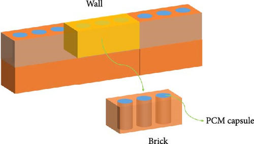
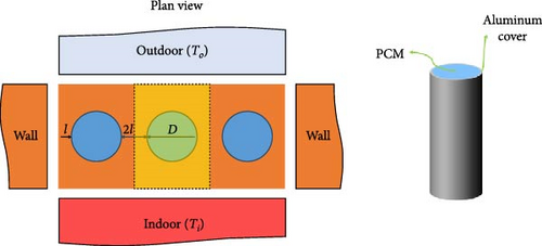
This study investigates the integration of PCM capsules within building bricks, arranged to form a wall, as depicted in Figure 1a. Cylindrical aluminum capsules of specified diameter (D = 50 mm) and thickness (t = 3 mm) were chosen for their ease of integration into bricks (L = 225 mm, W = 112 mm, and H = 65 mm) and ability to prevent PCM leakage during melting. Each capsule is filled with hexadecane, a PCM with a melting point of 19°C, suitable for maintaining comfortable indoor temperatures. This work analyses a representative section of brick, including the brick material, the aluminum capsule, and the PCM it contains (highlighted in yellow in Figure 1b). The thermal boundary conditions applied to this section simulate a wall exposed to To on one side and Ti on the other (Figure 1b). The numerical study is conducted during the daytime hours between 7 AM and 7 PM, when the To is high, which can cause the building’s temperature to rise. As a result, the initial temperature at the beginning of the simulations is set to 18°C (at 7 AM), at which point the PCM is solid. Numerical simulations are conducted to determine the effects of a scenario in which the To (25–34°C) exceeds the Ti (18–24°C), and both To and Ti are greater than the melting point of PCM, resulting in heat transfer from the outdoor and indoor environment into the PCM. Thus, a portion of the heat is absorbed by the solid PCM, causing it to melt, while the remainder is transferred to the indoor environment. Furthermore, the buoyant force influences the behavior of the liquid phase of the PCM, which in turn affects the duration of the melting process. By conducting this study, we aim to gain insights into the thermal dynamics of the PCM-based wall system under varying temperature conditions. The main objectives of this study are to investigate the heat transfer mechanisms, the melting behavior of the PCM, and the impact of buoyancy on the performance of the PCM. The findings of this study will contribute to a better understanding of the wall’s thermal response and its effectiveness at regulating temperature fluctuations within the building envelope. Table 1 shows the required properties for each element, including hexadecane, aluminum cover, and brick.
| Properties | Hexadecane | Aluminum shell | Brick | Unit |
|---|---|---|---|---|
| Density (ρ) | 770 | 2640 | 1800 | kg/m3 |
| Thermal conductivity (k) | 0.2 | 108 | 0.72 | W/m·K |
| Specific heat capacity (Cp) | 2215 | 960 | 829 | J/kg·K |
| Thermal expansion coefficient (β) | 7 × 10⁻⁴ | — | — | 1/K |
| Dynamic viscosity (μ) | 3.03 × 10⁻³ | — | — | kg/ms |
| Melting temperature (Tm) | 19 | — | — | °C |
| Melting temperature range (Tmr) | 1 | — | — | °C |
| Latent heat (h) | 237 | — | — | kJ/kg |
3. Governing Equations
- •
The capsule wall is considered homogeneous and isotropic.
- •
The effects of solar radiation and other external heat sources are not considered in this study.
- •
PCM properties and behavior are assumed to be uniform throughout the capsules.
- •
Convection effects inside the PCM capsules are considered.
- •
PCM capsules are considered fully sealed and impermeable to prevent leaks during melting.
- •
The density variation of the PCM due to temperature changes is neglected for simplicity, while its effects on the buoyant force are analyzed through the use of the Boussinesq approximation.
- •
The thermal properties of brick, aluminum, and PCM are assumed to be constant within the temperature range of interest.
- •
The effects of phase change hysteresis and supercooling on the PCM are neglected.
The PDEs governing the thermal behavior of the PCM-based wall system can be divided into two distinct categories: momentum and energy equations for the PCM region and energy equations for the solid regions (brick and aluminum capsule).
3.1. PDEs for the PCM Region
3.2. The Energy Equation for the Solid Regions
4. Mesh and Validation
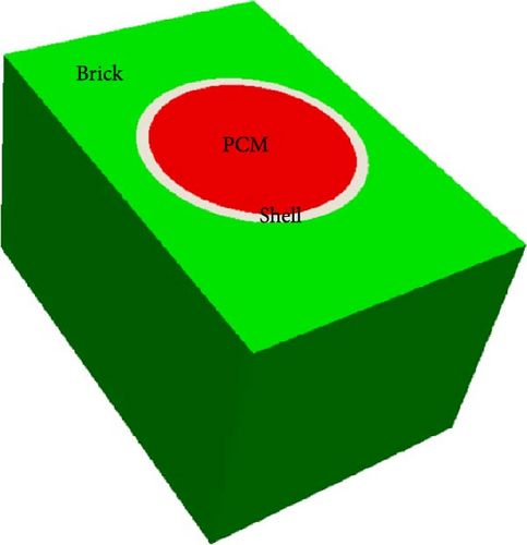
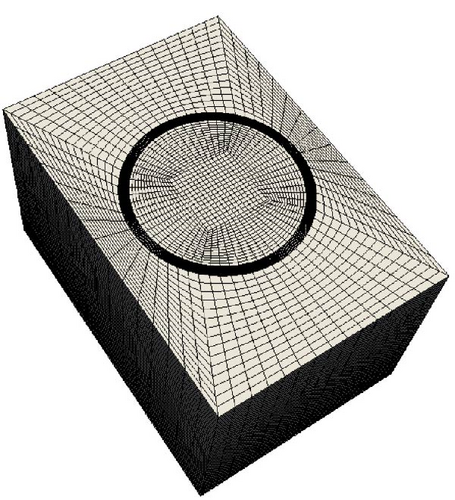
For this study, CFD calculations based on the finite volume method (FVM) are employed to model the PCM region during solid–liquid transitions as well as solid regions. A representative brick section containing a single PCM capsule is selected as a representative example of the symmetric conditions along the wall’s longitudinal direction (Figure 2a). The upwind and central schemes are utilized to discretize the divergence and Laplacian terms in the momentum and energy equations related to the PCM domain. The upwind scheme ensures stability and accuracy when capturing the flow behavior and heat transfer within the PCM, while the central scheme is applied to the energy equations for solid regions, which have simpler behavior. The Euler scheme is used for time discretization across all regions. Constructing a high-quality mesh is crucial for accurate and reliable CFD simulations. In this study, the cylindrical capsule is meshed using a combination of a square geometry at its center and a circular surrounding shape (Figure 2b), effectively capturing the capsule’s complex geometry while maintaining computational efficiency. A structured and uniform mesh is applied to the capsule shell to ensure accurate heat transfer representation within the PCM region. Conversely, an unstructured mesh is utilized for the brick region, allowing flexibility to adapt to its complex shape (Figure 2b). This numerical model accurately represents the physical phenomena within the PCM-based wall system by using these meshing strategies and discretization schemes, facilitating investigations of heat transfer, phase change, and fluid flow dynamics and providing valuable insight into the system’s thermal behavior and performance.
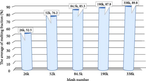
This study employs a variety of mesh configurations to discretize the computational domain to examine the sensitivity of the results to the mesh number. The purpose of using different mesh numbers is to evaluate the impact of mesh numbers on numerical simulations. To ensure numerical stability and accuracy, a specific condition (Ti = 18°C and To = 34°C) with a Courant number lower than 0.3 is applied to select the optimal mesh number. To evaluate mesh independence and determine the most appropriate mesh number, the average melting fraction is considered a critical parameter in this study. The melting fraction provides valuable insights into the phase change behavior of the PCM and is considered a key performance criterion for analysis. By comparing the average melting fraction obtained from different mesh configurations, the study aims to identify the mesh number that yields consistent and reliable results. Figure 3 presents the mesh sensitivity analysis results. The average melting fraction exhibits a significant difference between the 26k and 84.5k mesh configurations. However, as the mesh number increases to 190k, the difference in the average melting fraction diminishes, indicating improved convergence. Furthermore, there is no significant difference in the melting fraction between the 190k and 338k mesh configurations, suggesting that further refinement of the mesh would not have a significant impact on the results. Based on these findings, the study concludes that a mesh number of 190k provides the most effective option for modeling the system in subsequent cases. This mesh configuration strikes a balance between computational efficiency and accuracy, ensuring reliable predictions of the thermal behavior and phase change phenomena in the PCM-based wall system.
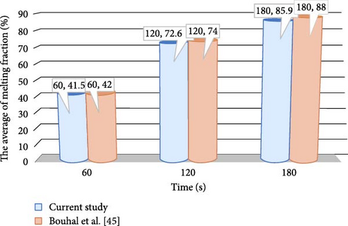
This study aims to validate the melting process of PCM. The results of this simulation are compared with those from a study by Bouhal et al. [54], which simulated the melting process of pure Gallium in a cylinder with four cylindrical heat sources maintained at a constant temperature above the melting point of Gallium. The average melting fraction from this study is compared against that found by Bouhal et al. [54] for a meaningful comparison. The comparison is conducted specifically using heat sources without fins in Bouhal et al.’s study [54] that maintained a constant temperature of 45°C at various time intervals (t = 60, 120, and 180 s). Figure 4 illustrates the comparison between the average melting fraction based on this study and the melting fraction reported by Bouhal et al. [54]. Results indicate an acceptable level of agreement between the two studies, indicating that the simulation in the present study effectively captures the key characteristics of the melting process, as evidenced by the similarity in average melting fractions. This agreement supports the validity and reliability of the simulation methods employed in this study. As this research focuses solely on validating the melting process of the PCM, future studies may broaden the analysis to include convective heat transfer and varying boundary conditions. The integration of these elements would provide a more comprehensive validation and increase the applicability of the simulation results.
5. Results and Discussions
The purpose of this numerical study is to investigate the temperature differences between outdoor and indoor environments comprehensively by simulating a variety of cases. The To considered in the analysis is set at 25, 28, 31, and 34°C, while the Ti is set at 18, 20, 22, and 24°C. Several key parameters are analyzed to gain insight into the thermal behavior of the PCM, including the average melting fraction, the heat flux from the indoor space, the temperature distribution across the simulated domain, and the melting fraction distribution within the PCM. By examining the average melting fraction, we gather valuable information about the extent of phase change occurring in the material. This metric sheds light on the PCM’s efficacy in absorbing and releasing thermal energy in response to fluctuations in To and Ti. The analysis of the heat flux from the indoor environment provides additional insight into the transfer of thermal energy between the indoor space and the surrounding environment. Through understanding the temperature distribution across the simulated domain, it is possible to analyze how temperatures varied, which provides vital information regarding the PCM’s ability to regulate Ti and minimize fluctuations. Additionally, analysis of the melting fraction distribution enables the identification of specific regions in the PCM where phase changes occurred, which enables a localized assessment of the material’s performance. Based on this comprehensive analysis, a deeper understanding is gained of the thermal behavior and performance of the PCM under a variety of Ti and To values.
5.1. Impact of Temperature Difference on the Average Melting Fraction
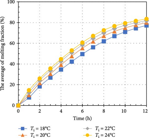
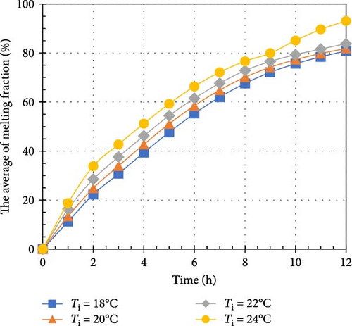
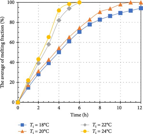
According to Figure 5, there is a significant relationship between the average melting fraction of the PCM and time for various indoor and outdoor temperature scenarios. Each curve in the plot corresponds to a specific Ti, while each plot represents a distinct To. In Figure 5a, it is evident that the average melting fraction increases linearly with time at Ti = 18°C. This linear behavior may be attributed to the relatively small temperature difference of 7°C between the indoor and outdoor environments, resulting in a gradual transfer of heat from both sources to PCM. Alternatively, for the curves associated with high Ti and To values, the average melting fraction displays a parabolic shape with negative concavity. This trend reflects the larger temperature differences, which lead to increased heat transfer rates and a more rapid melting process in PCM. When comparing the curves at a constant To, it is evident that higher Ti values accelerate the melting process. Particularly, higher Ti enhances heat transfer between the indoor environment and PCM, resulting in a greater proportion of PCM transitioning to the liquid phase. For example, when the Ti rises from 18 to 24°C, the average melting fraction at t = 12 h increases from 65.2% to 81.2% for a To = 25°C, from 80% to 83.5% for 28°C, and from 83% to 93.1% for 31°C. However, in Figure 5c, for To = 31°C, it is noteworthy that increasing the Ti from 18 to 22°C does not significantly affect the average melting fraction. This phenomenon occurs due to the already substantial temperature difference between the indoor and outdoor environments, where the heat transfer rate is high, making further increases in Ti have minimal impact on the melting fraction. Furthermore, Figure 5d illustrates that for Ti = 18 and 20°C, the average melting fraction reaches a fully liquid phase at t = 12 h. In contrast, at Ti = 22 and 24°C, this transition occurs much faster, at t = 6 h. This expedited melting process is attributed to the increased heat flux from both the indoor and outdoor environments, which supplies more thermal energy to PCM. In summary, Figure 5 highlights the relationship between Ti and To, the average melting fraction, and the time needed for PCM to undergo phase change. The findings emphasize the influence of temperature differences and heat transfer rates on the melting process, enhancing our understanding of PCM’s thermal behavior and performance. This knowledge supports the optimization of PCM-based systems for various applications.

5.2. Impacts of Temperature Difference on Heat Flux
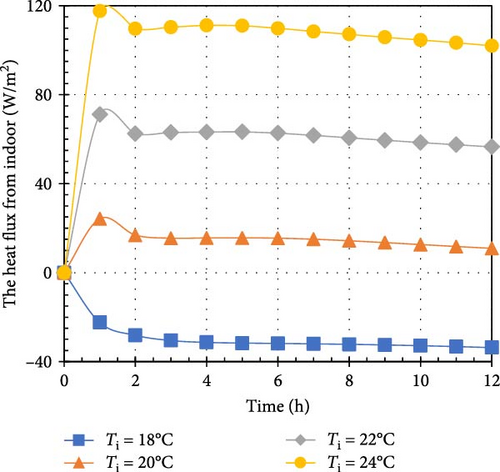
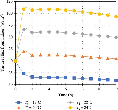
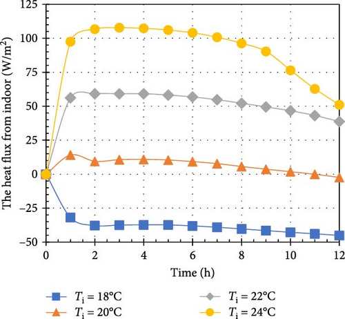
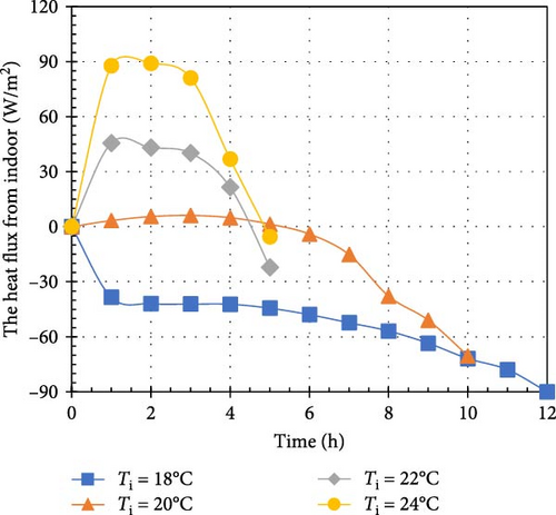
Figure 6 illustrates the heat flux from the indoor environment across various combinations of Ti and To values. For Ti = 18°C, the heat flux consistently showed negative values over time, indicating that heat was being transferred from both the outdoor environment and the PCM into the indoor space. Notably, the PCM was capable of absorbing some of the ambient heat. For instance, at Ti = 18°C, the heat flux varied from −33.7 to −40.6, −45.1, and −90 W/m2 as To increased from 25 to 28, 31, and 34°C at t = 12 h. The sharp rise in heat flux to −90 W/m2 at To = 34°C can be attributed to the PCM being fully melted at that time. Initially, the heat flux remained around −50 W/m2 from 0 to 6 h but surged to −90 W/m2 at t = 12 h due to the complete phase change of the PCM. Without PCM, the heat flux would remain negative due to the temperature difference between the indoor and outdoor environments. Figures 6a–c show the heat flux for To = 25, 28, and 31°C, respectively. Each graph reveals that the heat flux from the indoor environment abruptly increases from 0 W/m2 to a positive value at t = 1 h, then stabilizes, indicating heat transfer from the indoor space to the PCM. This behavior is due to the PCM remaining solid for less than an hour, during which it absorbs heat to raise its temperature. After 1 h, the PCM begins to melt while maintaining a constant temperature. All charts demonstrate that heat flux from the indoor environment increases with rising Ti. This trend results from an increase in temperature difference between the indoor environment and the PCM’s melting point, enhancing heat transfer to the solid PCM. For example, when the Ti increases from 20 to 24°C at To = 25°C, the heat flux rises from 11 to 102 W/m2. Similarly, at To = 28°C, the heat flux increases from 4.5 to 93 W/m2. The trend for To = 34°C differs from other temperatures, as PCM receives substantial heat from both environments, leading to faster melting. For Ti = 18 and 20°C, the heat flux remains negative, indicating heat entry from the outdoor environment. However, for Ti = 22 and 24°C, the heat flux becomes positive between 0 and 6 h, reflecting the higher Ti values that facilitate heat transfer to the PCM. In summary, Figure 6 provides a comprehensive picture of the heat flux generated by the indoor environment under a variety of temperature conditions. The results emphasize the PCM’s role in absorbing and releasing heat and highlight how temperature differences influence the heat transfer process.
5.3. Impacts of Temperature Difference on Temperature and Melting Fraction Distribution
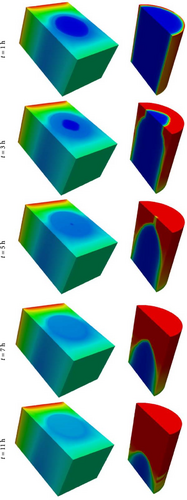
Figure 7 provides valuable insights into the distribution of temperature within the domain and the melting fraction of the PCM over time under the conditions of To = 28°C and Ti = 22°C. The temperature distribution reveals that heat from both the outdoor and indoor environments enters the PCM, as their temperatures are higher than the PCM melting point. Additionally, as time progresses, areas of minimum temperature can be observed within the PCM region from 0 to 12 h. The PCM melting process reveals that melting begins at t = 1 h, starting from the top areas and gradually progressing downward. This behavior is primarily influenced by buoyant forces; as the PCM melts in the lower regions, the resulting liquid, which is less dense than the solid phase, rises. Upon reaching the upper areas, the liquid cools and descends, creating a cyclical motion within the PCM. This dynamic results in a solid core remaining in the center of the PCM capsule. The observed temperature distribution and melting behavior underscore the intricate dynamics of heat transfer and phase change in the PCM. The melting process is driven by heat flux from both the outdoor and indoor environments, with the top areas of the PCM being the first to transition to the liquid phase. Over time, the melting front gradually advances toward the bottom until the entire PCM reaches a fully liquid state. These insights into the melting behavior and temperature distribution enhance the understanding of PCM’s thermal performance under specific temperature conditions. The knowledge gained from such research is essential for optimizing the design and operation of PCM-based systems in various applications, where precise control of the melting process and temperature distribution is essential.
5.4. TTEE
For the computation of Equations (10)–(23), it is necessary to account for a number of key parameters, including the coefficient of convection between the indoor and outdoor environment for the walls, roof, floor, windows, and doors. These coefficients are summarized in Table 2. Additionally, optical parameters such as absorbance and transmittance for various building components are also presented in Table 2. In addition, economic parameters, such as the project lifespan and discount rate, are included in the same table so as to provide a comprehensive overview necessary for our calculations. Additionally, it is important to note that the cost of each aluminum capsule, including fabrication and installation, has been incorporated into the installation cost.
| Parameter | Value | Parameter | Value |
|---|---|---|---|
| Average convective heat transfer between indoor and outdoor for the wall (Uwall) | 1.15 W/m.K | Average convective heat transfer between indoor and outdoor for the roof (Uroof) | 0.28 W/m.K |
| Average convective heat transfer between indoor and ground for the roof (Ufloor) | 1.81 W/m.K | Average convective heat transfer between indoor and outdoor for the window (Uwindow) | 1.0 W/m.K |
| Average convective heat transfer between indoor and outdoor for the door (Udoor) | 2.07 W/m.K | Ground temperature (Tground) | 10°C |
| Wall absorptivity (αwall) | 0.2 | Window absorptivity (τwindow) | 0.15 |
| Roof absorptivity (αroof) | 0.2 | Solar irradiance () | 800 W/m2 |
| House width | 10 m | House length | 10 m |
| House height | 3 m | Number of windows | 3 |
| Window area | 2 m2 | Number of doors | 1 |
| Door area | 3 m2 | Lifespan | 30 years |
| Discount rate | 2% | PCM price (PPCM) | 2.5 $/kg |
| Electricity price (Pele) | 0.36 $/kWh | Number of PCM capsules (Nc) | 13 m |
| Maintenance cost (Cm) | 250 $/year | Installation price (Pins) | 3 $/kg |
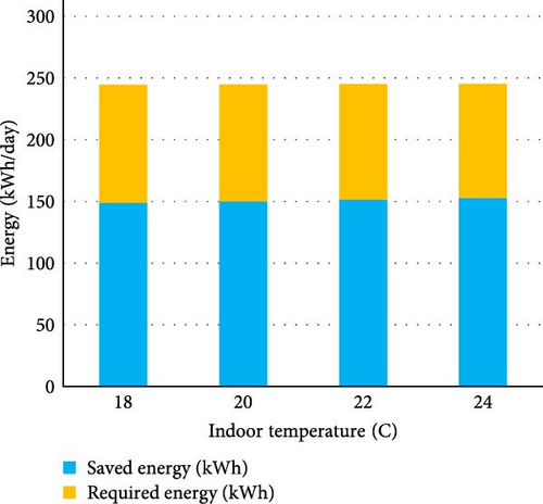
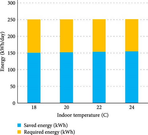
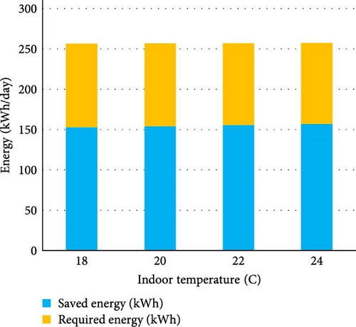
Figure 8 presents several bar plots that illustrate the energy savings achieved through the use of PCM-integrated bricks compared to the remaining energy required for cooling a house at varying Ti and To values. The results indicate that PCM-integrated bricks significantly reduce electricity consumption for cooling, as they effectively absorb heat transfer from the outside to the inside. Consequently, the energy required for cooling the house is considerably diminished. For example, this system can achieve energy savings of 59.6% when the To is 34°C and the Ti is 18°C, and 63.1% when the To is 25°C and the Ti is 24°C. Moreover, changes in Ti under the same outdoor conditions do not significantly affect energy savings, as the majority of heat transfer between the indoors and outdoors is attributed to solar irradiance. Additionally, an increase in To while maintaining the same Ti can result in a slight increase in both saved energy and required energy; for instance, raising the To from 25 to 34°C results in energy savings of ~4.2%.

Tables 3 and 4 present the economic parameters of NPV and IRR at the end of the project for various Ti and To values. According to Table 3, the use of PCM-integrated bricks can yield significant cost savings, ranging from $414.7k to $444.3k. Furthermore, an increase in Ti at a constant To can enhance the NPV, as the energy savings from the proposed system improve. For instance, raising the Ti from 18 to 24°C can lead to an increase of approximately $12,000 across all To values. Further, higher To values can increase the NPV by approximately $20,000. According to Table 4, the IRR for implementing this system ranges from 1.583 to 1.70, which is substantial when compared to the discount rate of 0.02. This indicates that the system represents a profitable investment opportunity for investors. Furthermore, increases in both Ti and To can further enhance the IRR, as they lead to increased energy savings resulting from the integration of PCM capsules into the bricks.
| To | Ti = 18°C | Ti = 20°C | Ti = 22°C | Ti = 24°C |
|---|---|---|---|---|
| To = 25°C | 414.7 | 418.6 | 422.6 | 426.6 |
| To = 28°C | 420.6 | 424.6 | 428.6 | 432.5 |
| To = 31°C | 426.6 | 430.5 | 434.5 | 438.4 |
| To = 34°C | 432.5 | 436.4 | 440.4 | 444.3 |
| To | Ti = 18°C | Ti = 20°C | Ti = 22°C | Ti = 24°C |
|---|---|---|---|---|
| To = 25°C | 1.583 | 1.601 | 1.624 | 1.635 |
| To = 28°C | 1.611 | 1.625 | 1.640 | 1.654 |
| To = 31°C | 1.632 | 1.647 | 1.662 | 1.677 |
| To = 34°C | 1.654 | 1.669 | 1.684 | 1.699 |
6. Conclusion
This study investigates the thermal performance and economic assessment of a PCM-integrated brick structure for passive cooling in warm climates, utilizing a novel CFD model that incorporates buoyant force effects within the PCM’s liquid phase. Numerical simulations explore various outdoor (25–34°C) and indoor (18–24°C) temperature scenarios, analyzing PCM melting fraction, heat flux, and temperature distribution. Results show that for Ti = 18°C, the heat flux from the indoor environment ranges from −33.7 to −90 W/m2 as the To increases from 25 to 34°C at t = 12 h, demonstrating the PCM’s ability to absorb incoming heat. Conversely, at higher Ti values (22 and 24°C), the heat flux from the indoor environment is positive between 0 and 6 h, as the Ti is high enough to transfer heat to the PCM. Additionally, the implementation of PCM-integrated bricks can lead to substantial cost savings, ranging between $414.7k and $444.3k. The IRR for this system is impressive, ranging from 1.583 to 1.70, significantly exceeding the discount rate of 0.02. This suggests a highly attractive investment opportunity. These findings confirm PCM’s effectiveness in modulating Ti and absorbing excess heat from both external and internal sources. The study also found that PCM melting begins in the top regions due to buoyant forces, highlighting the importance of taking these effects into account when simulating a PCM. This research contributes to the design of energy-efficient buildings that enhance occupant comfort and reduce environmental impact, providing a promising avenue for reducing air conditioning energy consumption.
Nomenclature
-
- PCM:
-
- Phase change material
-
- CFDs:
-
- Computational fluid dynamics
-
- HVAC:
-
- Heating, ventilation, and air conditioning
-
- ATF:
-
- Average temperature fluctuation
-
- TLL:
-
- Thermal load leveling
-
- OT:
-
- Operative temperature
-
- AHGR:
-
- Average heat gain reduction
-
- NNV:
-
- Natural night ventilation
-
- WWR:
-
- Window-to-wall ratio
-
- DRLESE:
-
- Dynamic rotating latent-energy-storage envelope
-
- SLESE:
-
- Static latent-energy-storage envelope
-
- TTEE:
-
- Techno-thermo-economic evaluation.
Conflicts of Interest
The authors declare no conflicts of interest.
Funding
Princess Nourah bint Abdulrahman University Researchers Supporting Project Number PNURSP2025R864, Princess Nourah bint Abdulrahman University, Riyadh, Saudi Arabia. Also, the authors gratefully acknowledge Ajman University for their generous support through Grant 2024-IRG-ENIT-30.
Acknowledgments
Princess Nourah bint Abdulrahman University Researchers Supporting Project Number PNURSP2025R864, Princess Nourah bint Abdulrahman University, Riyadh, Saudi Arabia. Also, the authors gratefully acknowledge Ajman University for their generous support through Grant 2024-IRG-ENIT-30.
Open Research
Data Availability Statement
The datasets used and/or analyzed during the current study are available from the corresponding author upon reasonable request.


