Amorphous Vanadium Oxide Nanoparticle-Impregnated Three-Dimensional Reduced Graphene Oxide and Nitrogen-Doped Carbon Nanotubes Composite Microspheres as Functional Interlayers for Lithium–Sulfur Batteries
Abstract
Herein, amorphous vanadium oxide (a-VOx) nanoparticle-impregnated three-dimensional (3D) microspheres comprising highly conductive and porous reduced graphene oxide (rGO) and nitrogen-doped carbon nanotubes (N-CNTs) framework (a-VOx@rGO-N-CNTs) were designed as functional interlayers for lithium–sulfur batteries (LSBs). N-CNTs were successfully formed on the rGO sheet surfaces, uniformly distributed between rGO and mesopores, via the catalytic effect of metallic Co–Fe. The rGO and N-CNTs framework not only provided an additional pathway for electron transport but also improved structural durability of the electrode materials. Moreover, polar a-VOx nanoparticles involved within the conduction pathway offered numerous chemisorption sites for anchoring polysulfides, thereby improving the utilization of active materials. The cell employing a-VOx@rGO-N-CNTs-coated separator as a functional interlayer exhibited excellent rate capabilities (473 mA h g−1 at 1.5 C) and cycling performance (800 cycles at 1.0 C and an average decay rate of 0.09% per cycle) at high C-rate. This outstanding performance was mainly ascribed to the synergistic effects of rGO, N-CNTs framework, and polar a-VOx nanoparticles. The design strategy proposed in this study offers insights into the development of porous and conductive nanostructures for extensive energy storage applications including LSBs.
1. Introduction
Currently, Li-ion batteries (LIBs) dominate the field of energy storage and are widely used in an extensive range of portable electronic devices and electric vehicles [1–6]. With the increasing demand for power grids or energy storage systems, LIBs are reaching their theoretical limits in terms of gravimetric and volumetric energy densities, prompting the exploration of alternative materials with higher energy/volume densities [5, 7, 8]. In this regard, lithium–sulfur batteries (LSBs) have been considered as next-generation energy storage devices capable of replacing LIBs owing to their exceptionally high energy densities (2600 Wh kg−1), high theoretical capacities (1675 mA h g−1), suitable average operating voltages (~2.1 V vs. Li/Li+), and the abundance of elemental S [5, 9–12]. Nevertheless, the applications of LSBs are hindered by some challenges including low electrical conductivities of elemental S and discharge products, reducing active material utilization [13–16]. Migration of lithium–polysulfides (LiPSs) toward the Li anode leads to material loss due to the “shuttle effect,” and additionally, volume expansion during the conversion of LiPSs induces electrode polarization [17–20].
Related ongoing efforts involve the employment of functional interlayers, which are a promising approach to address the critical shortcomings of LSBs mentioned earlier. Functional interlayers operate through electrocatalytic conversion to adsorb LiPSs migrating toward the Li anode, thereby effectively suppressing the shuttle effect and enhancing the active material utilization [21–25]. Carbonaceous materials, such as carbon nanotubes (CNTs) [26], carbon nanowires [27], graphene oxide (GO) [28], and porous activated carbon [29], have been employed as interlayers because of their excellent electrical conductivities, mechanical strengths, and the presence of macro- and meso-pores. However, despite providing physical adsorption sites for polar LiPSs, nonpolar carbonaceous materials face limitations in effectively suppressing the shuttle effect due to their inherently weak interactions with LiPSs [30–32]. To overcome the limitations of carbonaceous materials, polar materials, including alloys [33], metal oxides [34], nitrides [5], sulfides [35], and phosphides [36], and heteroelement (─N, ─O, ─P, and ─S) doping [37] have been utilized to chemically anchor LiPSs [38, 39]. Therefore, combining carbonaceous materials with metal compounds is necessary to achieve efficient adsorption and conversion of LiPSs.
Graphene, a two-dimensional (2D) material, has gained attention as a carbonaceous material owing to its outstanding physical and electrical properties, effectively mitigating charge-transfer resistance (Rct) during charge–discharge [28, 40–42]. Nevertheless, the chemical reduction of GO for energy-related applications leads to the persistent issue of irreversible aggregation of graphene layers due to van der Waals interactions between them [43–46]. Various studies have been conducted to address this irreversible aggregation [44, 47, 48]. Recently, the preparation of graphene with a paper-ball-like morphology and introduction of CNTs as spacers between graphene layers have attracted attention for strengthening the resistances of graphene layers against aggregation [49]. Among the various synthesis methods, in particular, chemical vapor deposition (CVD) method has mainly been adopted [50]. This process employs transition metal nanocrystals present on the surface of graphene as catalysts to facilitate the vertical growth of CNTs between graphene layers. The resulting graphene composites feature CNTs that interconnect graphene sheets, effectively preventing restacking. These composites exhibit outstanding mechanical and electrical properties and have been reported to show enhanced electrochemical performance when utilized as anode materials [51, 52].
Accordingly, in this study, a new strategy for the fabrication of metal oxide-3D (three-dimensional) reduced GO (rGO) and N-doped CNTs composite microspheres (metal oxide@rGO-N-CNTs) is successfully reported, involving spray pyrolysis, CVD, and a simple drop-and-dry process. Amorphous vanadium oxide (a-VOx)@rGO-N-CNTs are prepared as the first target material. The redox potential of VOx is slightly higher than those of LiPSs (~2.4 V), contrary to the cases of other metal oxides such as TiO2, Co3O4, and Cu2O. This is attributed to the high reactivity of VOx toward LiPSs and enables efficient anchoring of high-order Li2Sx (x ≥ 4). Furthermore, the amorphous phase, whose open framework affords multiple penetration pathways, enhances the ion mobilities and charge storage capabilities of rGO-N-CNTs, thereby improving the conductivities of electrode materials. Moreover, a-VOx@rGO-N-CNTs have been applied as functional interlayers in LSBs, exhibiting stable cycling performances and excellent rate capabilities.
2. Materials and Methods
Crumpled rGO microspheres were prepared by spray pyrolysis. During spray pyrolysis, droplets were generated using a 1.7 MHz ultrasonic spray generator consisting of six vibrators. Spray solution was fabricated by dissolving 0.02 M Co(NO3)2·6H2O (98.0%, Junsei) and Fe(NO3)3·9H2O (98.5%, Samchun chemical) in a 1:1 ratio, 1.0 mg mL−1 GO, and 1.0 g mL−1 of 100 nm polystyrene (PS) nanobeads in 500 mL distilled water. GO was synthesized from graphite flakes using a modified Hummer’s method [53], and PS nanobeads were prepared using emulsion polymerization, as described in our previous study [54]. The droplets were transferred to a quartz reactor, with a length of 1200 mm and diameter of 50 mm, and the temperature of the reactor was maintained at 400°C using air as the carrier gas at a flow rate of 20 L min−1. To form rGO-N-CNTs, the sprayed precursor was subjected to CVD with dicyandiamide (DCDA) in a tube furnace. The process involved heating the sprayed precursor at 300°C for 3 h, followed by subsequent heating at 750°C for 2 h at a rate of 5°C min−1 under a 10% H2/Ar atmosphere. Based on 1.0 g rGO-N-CNTs powder, 1.5 g vanadyl acetylacetonate (C10H14O5V, Samchun Chemical) was dissolved in high-purity ethyl alcohol. The resulting solution was introduced into the rGO-N-CNTs powder. Oxidation at 250°C for 3 h under an air atmosphere transformed C10H14O5V@rGO-N-CNTs into a-VOx@rGO-N-CNTs. Detailed information about the characterizations and electrochemical measurements of the prepared samples is provided in the Supporting Information.
3. Results and Discussion
Procedure for the synthesis of a-VOx@rGO-N-CNTs is depicted in Scheme 1. Spray pyrolysis was specifically used to produce microsphere composites of metal salts and polymers in a uniformly dispersed state within the spray solution. Droplets generated by the ultrasonic nebulizer contained evenly dispersed GO nanosheets, cobalt and iron ions, and PS nanobeads. As the droplets passed through the tubular reactor maintained at 400°C using the carrier gas, GO nanosheets converted into crumpled rGO microspheres, whereas Co–Fe oxide nanocrystals were homogeneously dispersed on the rGO surface, and the PS nanobeads were surrounded by rGO nanosheets. Thereafter, the sprayed precursor was post-treated with DCDA under an inert atmosphere to synthesize rGO-N-CNTs. In the initial step of this process, metallic Co–Fe alloys formed via the reduction of Co–Fe oxide nanocrystals, while the PS nanobeads decomposed, resulting in uniform pores with a mean size of 100 nm inside the microspheres. In the subsequent step, metallic Co–Fe facilitated N-CNT growth from the carbon nitride gas generated by the decomposition of DCDA through its catalytic effect. Moreover, N-CNTs grew inside the microspheres, utilizing the pores derived from the decomposition of PS nanobeads. The resulting rGO-N-CNTs microspheres with high pore volumes served as templates for the infiltration of metal salt solution. Vanadyl acetylacetonate, used as the vanadium source, was dissolved in high-purity ethyl alcohol followed by infiltration into rGO-N-CNTs using the drop-and-dry process. Vanadium salt solution impregnated in the microspheres transformed into a-VOx nanoparticles via oxidation at a low temperature of 250°C. Finally, the obtained a-VOx@rGO-N-CNTs were coated on a commercial Celgard separator, and the resulting separator was applied as a functional interlayer for an LSBs.
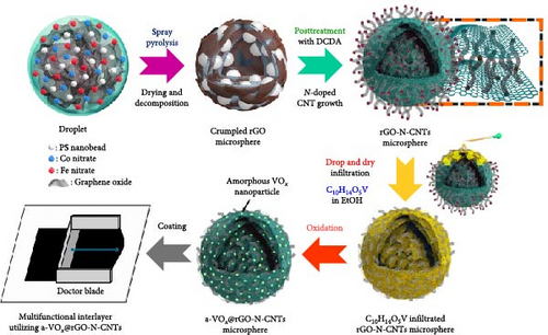
Morphological and crystal structure characteristics of the sprayed precursor are shown in Figure S1. The sprayed precursor demonstrates a crumpled ball morphology, consisting of 2D structured graphene sheets and spherical shape with a smooth surface (Figure S1a,b), which is attributed to the undecomposed PS nanobeads. X-ray diffraction (XRD) pattern of the sprayed precursor (Figure S1c) is broad with no discernible peaks, indicating that the Co–Fe oxide nanocrystals exist in extremely small sizes, and PS nanobeads are in less degraded states. Morphological characteristics of rGO-N-CNTs synthesized via posttreatment of the sprayed precursor with DCDA are depicted in Figure 1. Low-magnification scanning electron microscopy (SEM) image shown in Figure 1a confirms the uniform growth of CNTs on the crumpled rGO microsphere surfaces via the catalytic effect of metallic Co–Fe. Transmission electron microscopy (TEM) images (Figure 1b,c) reveal even growths of CNTs inside the rGO microspheres owing to the catalytic effect of metallic Co–Fe distributed throughout the microspheres. Moreover, the porous structures of rGO-N-CNTs are verified to be generated by the decomposition of PS nanobeads, and these microspheres exhibit hierarchical structures in which graphene layers are interconnected by N-CNTs. High-resolution (HR)-TEM image (Figure 1d) demonstrates clear lattice fringes separated by the interplanar spacings of 0.20 and 0.21 nm corresponding to the (110) and (330) crystal planes of Co3Fe7 and Co0.72Fe0.28 phase. Selected area electron diffraction (SAED) pattern (Figure 1e) indicates the existences of Co3Fe7 and Co0.72Fe0.28 phase. Elemental mapping image (Figure 1f) reveals homogeneous distribution of Co–Fe in the carbon matrices of rGO and CNTs. Additionally, the N signal is associated with N-CNTs grown by the decomposition of DCDA. N-CNTs improve the electrical conductivities of the electrode materials and facilitate the anchoring of LiPSs.
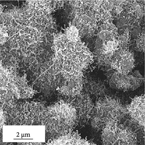
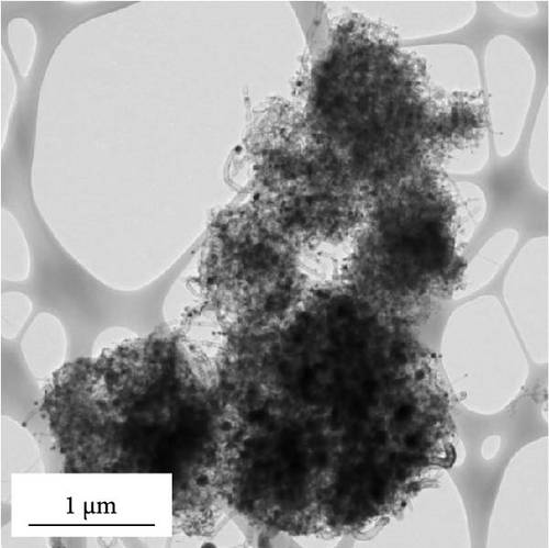
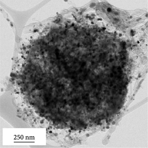
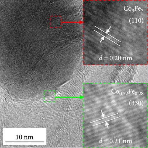
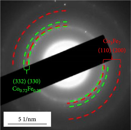
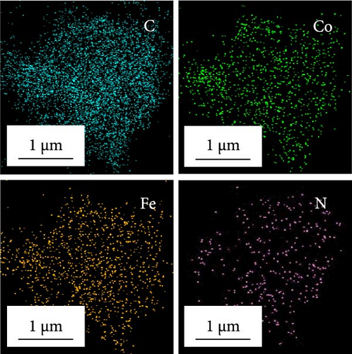
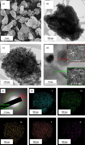
Morphological characteristics of a-VOx@rGO-N-CNTs, which were prepared from rGO-N-CNTs via the drop-and-dry process using a vanadium salt solution, are shown in Figure 2. Low-magnification SEM images (Figure 2a) demonstrate that the surfaces of a-VOx@rGO-N-CNTs are smoother compared to those of rGO-N-CNTs (low-magnification SEM images shown in Figure 1a), which implies uniform impregnation of a-VOx nanocrystals throughout the microsphere surfaces. TEM images (Figure 2b,c) indicate that rGO-N-CNTs are sufficiently filled with a-VOx nanoparticles. Moreover, the characteristics of rGO-N-CNTs are appropriately retained even after oxidation, and these microspheres serve as stable templates for the infiltration of vanadium salt solution. HR-TEM image (Figure 2d) reveals lattice fringes separated by 0.20 and 0.21 nm corresponding to the (110) and (330) crystal planes of Co3Fe7 and Co0.72Fe0.28 phase. Absence of the lattice fringe related to VOx is ascribed to the amorphous phase resulting from oxidation conducted at a low temperature of 250°C. SAED pattern (Figure 2e) demonstrates the presence of Co3Fe7 and Co0.72Fe0.28 phase. Corresponding elemental mapping images (Figure 2f) confirm the existence of Co–Fe in the carbon matrix along with N-CNTs. Furthermore, the V signal clearly implies that the a-VOx nanoparticles are homogeneously dispersed in the C matrix.
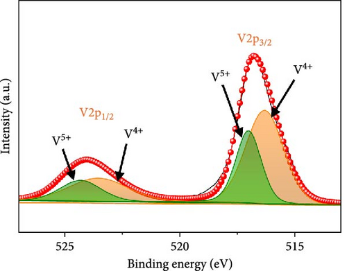
XRD patterns of rGO-N-CNTs and a-VOx@rGO-N-CNTs are depicted in Figure S2. In the XRD pattern of a-VOx@rGO-N-CNTs, the absence of peaks related to VOx comfirm the presence of amorphous VOx nanoparticles. Additionally, the XRD patterns of both samples exhibit diffraction peaks associated with Co0.72Fe0.28 and Co3Fe7 phase, which act as catalysts for CNT growth. Chemical states of the several elements in a-VOx@rGO-N-CNTs were evaluated by X-ray photoelectron spectroscopy (XPS) (Figure 3). HR V 2p spectrum of a-VOx@rGO-N-CNTs (Figure 3a) demonstrates V 2p3/2 and V 2p1/2 orbital peaks related to V4+/V5+ oxidation states at the binding energies of 516.3/517.0 and 523.5/524.3 eV, respectively [55, 56]. The V5+ oxidation state is attributed to the oxidation of vanadium components near the surface in contact with air [56, 57].
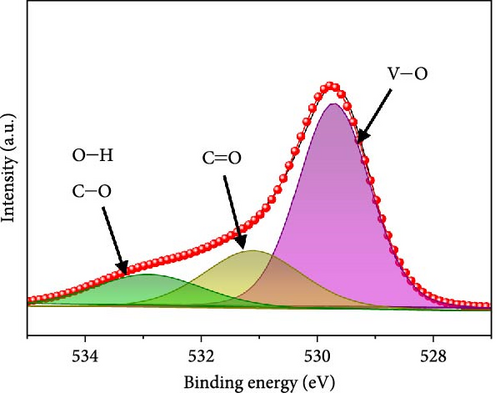

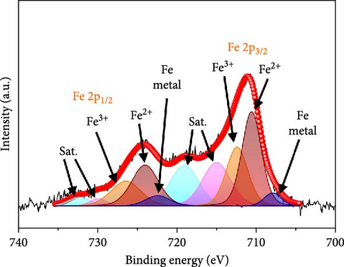
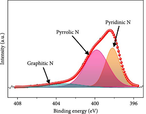
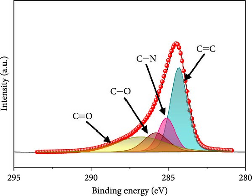
In the O 1s spectrum (Figure 3b), the three distinct peaks at 529.7, 531.1, and 532.9 eV corresponding to V─O, C═O, C─O, and O─H bonds are clearly observed [58]. Co 2p spectrum (Figure 3c) was deconvoluted into Co 2p3/2 and Co 2p1/2 orbital peaks at the binding energies of 780.6 eV and 796.3 eV, respectively. The Co 2p3/2 (778.6 eV) and Co 2p1/2 (794.9 eV) peaks are located at binding energies that are in accordance with those of the related peaks of metallic cobalt [59]. Additional Co 2p3/2 and Co 2p1/2 peaks are noticed at 780.4/796.2 and 782.2/797.4 eV, respectively, corresponding to Co3+ and Co2+, along with four satellite peaks [60–62]. Fe 2p spectrum (Figure 3d) exhibits several doublet peaks at 707.9/722.4, 710.5/724.0, and 712.4/726.4 eV, attributed to metallic Fe, Fe2+, and Fe3+, respectively [59, 63]. Satellite peaks are detected at ~717.1 and 731.3 eV. Deconvoluted N 1s spectrum (Figure 3e) demonstrates three peaks at 398.2, 399.8, and 403.1 eV corresponding to pyridinic N, pyrrolic N, and graphitic N, verifying the existence of N-doped carbon framework [64]. C 1s spectrum (Figure 3f) was deconvoluted into four peaks at 284.3 eV, 285.1 eV, 285.8 eV, and 286.8 eV related to C═C, C─N, C─O, and C═O, respectively [65, 66]. Presence of the peak of C─N bond at 285.1 eV implies the existence of N-CNTs, which improve the electrical conductivities and chemical activities of the electrode materials [22].
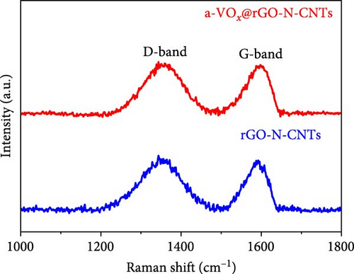
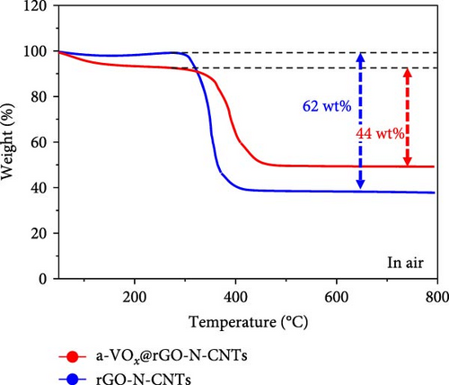
Raman spectra of a-VOx@rGO-N-CNTs and rGO-N-CNTs (Figure 4a) commonly exhibit D-bands near 1354 cm−1 and G-bands near 1595 cm−1, respectively. D- and G-bands are characteristic bands of carbonaceous materials, for example, disordered and graphitic carbon materials. The intensity ratios of D- to G-bands (ID/IG) for a-VOx@rGO-N-CNTs and rGO-N-CNTs are 1.02 and 1.07, respectively. Proximities of the ID/IG values for the two samples to 1.0 are attributed to the influences of the defects induced by N-CNT growth. Thermogravimetric (TG) curves of a-VOx@rGO-N-CNTs and rGO-N-CNTs are shown in Figure 4b. To determine the contents of carbon and a-VOx in a-VOx@rGO-N-CNTs, XRD pattern of the sample obtained after the oxidation of rGO-N-CNTs at 800°C was analyzed (Figure S3). Considering the oxidized product CoFe2O4-Co3O4, the carbon content of rGO-N-CNTs is calculated as 66.4 wt%. Finally, taking the amount of impregnated vanadyl acetylacetonate into account, the contents of a-VOx and carbon in a-VOx@rGO-N-CNTs are evaluated as 31.9 and 45.2 wt%, respectively. Specific surface areas and pore structures of a-VOx@rGO-N-CNTs and rGO-N-CNTs were evaluated using Brunauer–Emmett–Teller (BET) and Barrett–Joyner–Halenda (BJH) methods. N2 adsorption–desorption isotherms (Figure S4) demonstrate a combination of type IV and H3 hysteresis loops, indicating the formation of a hierarchical mesoporous structure. BET surface areas of a-VOx@rGO-N-CNTs and rGO-N-CNTs are 19.2 and 253.4 m2 g−1, respectively, and the corresponding pore volumes are 0.15 and 0.56 cm3 g−1. Different tendencies of the specific surface areas and pore volumes of the two samples reveal that the vanadium salt solution is sufficiently absorbed by the interior pores of rGO-N-CNTs, and subsequently, a-VOx nanoparticles are produced after the oxidation of resulting rGO-N-CNTs.
The physical properties and microstructure analysis of the synthesized a-VOx@rGO-N-CNTs-coated separator are presented in Figure S5. A digital image of the separator before being punched into a circular disk (Figure S5a) demonstrates a uniform coating without visible cracks. Additionally, Figure S5b shows the mechanical integrity and flexibility of the separator, showing its ability to withstand folding and bending stresses. The cross-sectional FE-SEM image of the pristine Celgard separator (Figure S5c) reveals a thickness of ~26.8 µm. Furthermore, the image of the separator coated with a-VOx@rGO-N-CNTs (Figure S5d) clearly shows that the coating is evenly applied over the Celgard separator, with a thickness of about 14.3 µm.
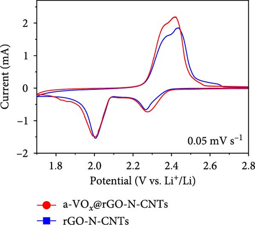
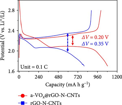
Electrochemical behaviors of Li-S cells featuring a-VOx@rGO-N-CNTs and rGO-N-CNTs-coated separators as functional interlayers are depicted in Figure 5. The initial CV curve acquired at a scan rate of 0.05 mV s−1 (Figure 5a) exhibits typical redox reaction characteristics involving elemental S only. For instance, in the CV curves of the cells comprising a-VOx@rGO-N-CNTs- and rGO-N-CNTs-coated separators, two distinct cathodic peaks are observed at 2.28/2.00 and 2.26/2.00 V, respectively. These peaks correspond to the successive reduction of elemental S to soluble high- and middle-order polysulfides (Li2Sx; 4 ≤ x ≤ 8) as intermediates, followed by conversion of these intermediates to low-order polysulfides (Li2Sx; 1 ≤ x ≤ 3) [34, 36, 67]. Corresponding anodic sweep demonstrates two closely spaced peaks at 2.36/2.41 and 2.38/2.44 V for a-VOx@rGO-N-CNTs- and rGO-N-CNTs-coated separators, respectively. This implies effective transformation of low-order polysulfides to high-order polysulfides and subsequently to elemental S [67–69]. Furthermore, the exactly overlapping CV profiles during the initial five cycles (Figure S6) indicate highly reversible redox processes in the cells. Additionally, the relatively higher current intensities of the cell employing the a-VOx@rGO-N-CNTs-coated separator as the functional interlayer (Figure 5a) suggests fast redox kinetics. The Li-S cell utilizing the a-VOx@rGO-N-CNTs-coated separator exhibits a lower polarization potential (ΔV = 0.20 V) as compared to that of the cell containing the rGO-N-CNTs-coated separator (ΔV = 0.35 V) (Figure 5b). These observations predict higher specific discharge capacities for the cell featuring the a-VOx@rGO-N-CNTs-coated separator relative to those for the cell comprising the rGO-N-CNTs-coated separator. To verify the CV results, initial charge–discharge potential profiles were obtained at 0.1 C (Figure 5b). The corresponding plateaus confirm that the electrochemical reactions are in appropriate agreement with the acquired peak positions in the CV curves. Cells with the a-VOx@rGO-N-CNTs-coated separators demonstrated extended charge–discharge plateaus, indicating higher discharge capacities of these cells owing to their better redox reactions. Correspondingly, the Li-S cells consisting of a-VOx@rGO-N-CNTs- and rGO-N-CNTs-coated separators delivered initial discharge capacities of 1084 and 798 mA h g−1, respectively, at 0.1 C. Rapid redox reaction of the cell containing the a-VOx@rGO-N-CNTs-coated separator as compared to that of the cell comprising the rGO-N-CNTs-coated separator can be ascribed to the synergistic effect of the highly conductive mesoporous framework comprising adequately entangled rGO and N-CNTs and the presence of multiple chemisorption sites in the forms of polar components (namely, a-VOx and metallic Co–Fe alloy). Moreover, heteroatom-doped CNTs serve as additional polarity sites, enhancing the overall LiPSs anchoring ability of the nanostructure.
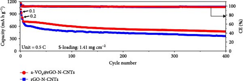

Cycling performances of the Li-S cells utilizing different separators were also evaluated at 0.5 C, as shown in Figure 5c and Figure S7c. Cell with the a-VOx@rGO-N-CNTs-coated separator exhibits an initial discharge capacity of 731 mA h g−1 (43.6% of the theoretical value) at 0.5 C, whereas the cell with the rGO-N-CNTs-coated separator demonstrates a lower initial discharge capacity of 711 mA h g−1. At the end of the 400th cycle, the cells employing a-VOx@rGO-N-CNTs- and rGO-N-CNTs-coated separators retain 63.7% (466 mA h g−1) and 49.6% (353 mA h g−1) of their initial capacities, respectively. Additionally, the average discharge capacity loss per cycle for the cell utilizing the a-VOx@rGO-N-CNTs-coated separator is 0.09% compared to 0.13% for the cell comprising the rGO-N-CNTs-coated separator. To optimize the a-VOx content, a solution containing 3.0 g vanadyl acetylacetonate was impregnated into rGO-N-CNTs and then oxidized to synthesize excessive-a-VOx@rGO-N-CNTs (denoted as Ex-a-VOx@rGO-N-CNTs). As shown in Figure S7a,b, Ex-a-VOx@rGO-N-CNTs exhibit a severely aggregated morphology. The cell with the Ex-a-VOx@rGO-N-CNTs-coated separator showed an initial discharge capacity of 635 mA h g−1 at 0.5 C (Figure S7c). However, after 400 cycles, the discharge capacity of 323 mA h g−1 (average decay rate of 0.15% per cycle), indicating that excessive amounts of a-VOx can reduce long-term stability. This suggests that the excessive a-VOx leads to material agglomeration during cycling, and the reduced specific surface area does not effectively mitigate volume expansion. Consequently, this configuration is not suitable for long-term cycling.
The stable cycling performance of the cell featuring rGO-N-CNTs-coated separator is attributed to the presence of metallic Co–Fe alloy and higher specific surface areas of rGO-N-CNTs, slightly facilitating both chemical and physical adsorptions of intermediate polysulfides; however, to a lower extent. This reduces the active material utilization due to unfavorable redox reactions and leads to relatively inferior discharge capacity retention during long-term cycling. This is evidenced by the charge–discharge potential profiles acquired at various cycle intervals for the cells consisting of different coated separators, as depicted in Figure S8a,c. To thoroughly evaluate the capacity and performance enhancement effect of the modified separator, cycling tests were performed using a Li-S cell with a pristine separator that was not coated with any material (Figure S9). The Li-S cell using pristine separators exhibited poor capacity retention and overall cycling performance compared to those with modified separators. This deficiency is due to the lack of active sites required to adsorb LiPSs, leading to the loss of active material and subsequent capacity degradation. In contrast, the modified separators provide these active sites, resulting in improved performance and stability, as demonstrated in Figure 5c. The cell employing the a-VOx@rGO-N-CNTs-coated separator actively anchored soluble LiPSs due to the presence of extra polar components, increasing the utilization of active materials and improving the discharge capacity. Furthermore, the a-VOx@rGO-N-CNTs-coated separator demonstrates an average energy efficiency of 73.1%, indicating the high reversibility of redox reactions, whereas the energy efficiency for the cell with the rGO-N-CNTs-coated separator was 69.7%. In addition, as shown in Figure S8a,c, the voltage efficiency of the cell employing the a-VOx@rGO-N-CNTs-coated separator was measured as 87.7%, reflecting reduced polarization during cycling, in contrast to 82.6% for the cell with the rGO-N-CNTs-coated separator. This highlights the enhanced electrochemical processes between Li2S and elemental S promoted by a-VOx during prolonged cycling. Cycling performance trends are similar even at a high current density of 1.0 C, as observed in Figure S10. After the activation steps, the initial discharge capacities of the cells utilizing the a-VOx@rGO-N-CNTs- and rGO-N-CNTs-coated separators were measured as 567 and 585 mA h g−1, respectively. However, after 800 cycles, the cell featuring the a-VOx@rGO-N-CNTs-coated separator exhibits a lower capacity decay (0.09%, 160 mA h g−1) as compared to that of the cell comprising the rGO-N-CNTs-coated separator (0.11%, 79 mA h g−1), indicating superior active material utilization during cycling in the case of the cell with the a-VOx@rGO-N-CNTs-coated separator. This is supported by the charge–discharge potential profiles, as shown in Figure S8b,d. Therefore, the improved cycling performances of the cell with the a-VOx@rGO-N-CNTs-coated separator at both low and high C-rates again demonstrate the structural advantages of a-VOx@rGO-N-CNTs. Furthermore, to verify the operational efficiencies of the functional interlayers, the cycling performances of the cells containing high sulfur loading electrodes (2.05 mg cm−2) and low electrolyte/sulfur ratios (15 μL mg−1) were also assessed at a C-rate of 0.3 C (Figure 5d). The relatively lower capacity of the a-VOx@rGO-N-CNTs-coated separator up to 200 cycles can be attributed to the reduced porosity caused by the impregnation of a-VOx, which increases the diffusion length for charged species under these challenging conditions. However, by the 500th cycle, the Li-S cells utilizing the a-VOx@rGO-N-CNTs-coated separator exhibit a discharge capacity of 274 mA h g−1, while the cell with the rGO-N-CNTs-coated separator shows a discharge capacity of 57 mA h g−1. The corresponding average discharge capacity retentions of 45.7% and 8.0%, respectively. Similarly, the voltage and energy efficiency of the cell employing the a-VOx@rGO-N-CNTs-coated separator were measured as 86.2% and 72.5%, respectively, demonstrating enhanced performance compared to 84.1% and 69.8% for the cell with the rGO-N-CNTs-coated separator. These results firmly validate the applicability of the a-VOx@rGO-N-CNTs-coated separator paired with high sulfur content and ultra-low electrolyte volume for feasible applications.
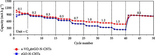
Rate capability tests of the Li-S cells were also conducted at several C-rates ranging from 0.1 to 1.5 C (Figure 5e and Figure S7d). The cell using a-VOx@rGO-N-CNTs-coated separator achieved discharge capacities of 952, 851, 779, 697, 613, 567, 528, and 473 mA h g−1 at 0.1, 0.2, 0.3, 0.5, 0.7, 1.0, 1.2, and 1.5 C, respectively, at the fifth cycle of each C-rate. Comparatively, the cell employing rGO-N-CNTs-coated separator demonstrated discharge capacities of 917, 810, 737, 634, 481, 391, 325, and 227 mA h g−1 at identical C-rates. Moreover, the average energy efficiency of the a-VOx@rGO-N-CNTs-coated separator was consistently higher across all C-rates compared to that of the rGO-N-CNTs-coated separator, further demonstrating its improved operational efficiency. Detailed energy efficiency values for each C-rate are provided in Table S1, offering a comprehensive comparison of the separators’ performance during the rate capability tests. Additionally, Ex-a-VOx@rGO-N-CNTs-coated separator exhibited discharge capacities of 789, 665, 592, 515, 459, 422, 384, and 328 mA h g−1 at the same C-rates. Notably, the two cells with a-VOx@rGO-N-CNTs—and rGO-N-CNTs-coated separators exhibit similar discharge capacities at low current densities, primarily due to the high specific surface areas of rGO-N-CNTs that enable physical adsorption of LiPSs. However, the absence of a-VOx as an additional polar material in rGO-N-CNTs causes inefficient trapping of the sulfur species thus resulting in LiPSs migration toward the anode. This leads to sustained active material loss and hence low discharge capacities, especially at high C-rates. In contrast, at high current densities (1.0 C and above), the cell with Ex-a-VOx@rGO-N-CNTs-coated separator shows improved performance compared to the cell with rGO-N-CNTs-coated separator, demonstrating the beneficial role of the excess a-VOx in capturing LiPSs and improving sulfur utilization. Despite this improvement at higher C-rates, Ex-a-VOx@rGO-N-CNTs-coated separator does not perform as well overall as the different coated separator. Furthermore, when the C-rate recovers from 1.5 to 0.1 C, both a-VOx@rGO-N-CNTs- and rGO-N-CNTs-coated separators demonstrate reversible discharge capacities of 855 mA h g−1, whereas the cell with Ex-a-VOx@rGO-N-CNTs-coated separator shows a lower capacity (681 mA h g−1). This suggests that excess a-VOx may hinder reversibility at low C-rates due to potential aggregation and supersaturation of the active sites, as well as increased pathways for charged species migration, leading to lower Coulombic efficiency and reduced specific capacity. The dramatic disparity in rate capability results of the two cells with a-VOx@rGO-N-CNTs- and rGO-N-CNTs-coated separators is due to the presence of a-VOx nanocrystals impregnated in the conductive matrix which effectively capture LiPSs species and mitigate the diffusion of these species toward the Li anode, thus improving sulfur utilization. Additionally, the highly entangled N-CNTs and rGO matrix promotes fast redox processes through the rapid migration of charged species. As shown in Table S2, the Li-S cell utilizing a-VOx@rGO-N-CNTs-coated separator exhibited comparable or superior electrochemical properties compared to previously reported interlayer materials. Charge–discharge potential profiles of the cells with the a-VOx@rGO-N-CNTs- (Figure S11a) and rGO-N-CNTs-coated separators (Figure S11b) acquired at various C-rates confirm the above results. Moreover, elemental S utilization bar charts were created for both cells at all C-rates, as shown in Figure S12. These bar charts clearly reveal that the cell employing the a-VOx@rGO-N-CNTs-coated separator delivers higher capacity utilization, suggesting enhanced sulfur participation, supported by more kinetically efficient redox processes.
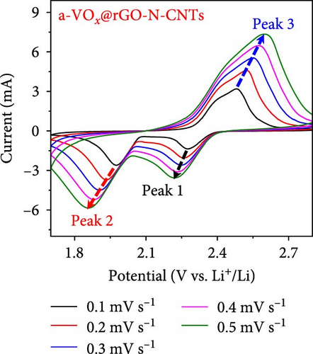
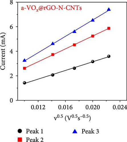
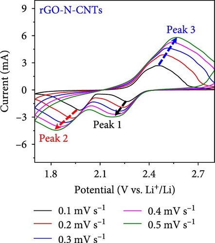
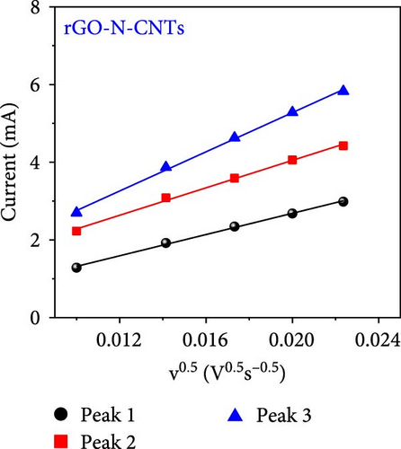
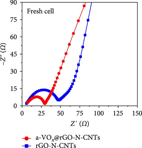
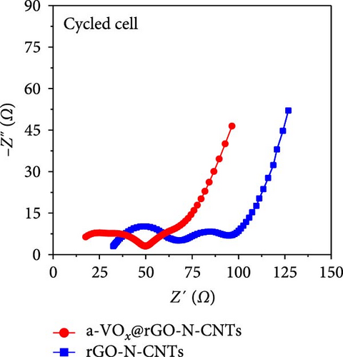
As observed, the cell paired with a-VOx@rGO-N-CNTs-coated separator exhibits an ~1.8 times higher diffusion coefficient value (5.13 × 10⁻⁸ cm2 s−1) compared to cell featuring rGO-N-CNTs-coated separator (2.75 × 10⁻⁸ cm2 s−1). This indicates that the nanostructure comprising N-CNTs and rGO as a conductive matrix ensures rapid electron transfer during the electrochemical reaction, thereby improving the redox kinetics. Moreover, electrochemical impedance spectroscopy (EIS) profiles were used to further validate the reaction kinetics at the electrode–separator–electrolyte interface in the assembled Li-S cells before (Figure 6e) and after (Figure 6f) cycling. Additionally, the semicircles in the Nyquist plots were represented by the equivalent circuit model, which involved a combination of several parameters in both series and parallel configurations (Figure S13). Table S4 presents all EIS parameters for the Li-S cells with different coated separators before and after cycling. Impedance was evaluated for all the Li-S cells in fully charged states before cycling at an open-circuit voltage and at the end of the 400th cycle at 0.5 C. Li-S cells featuring different coated separators exhibit moderate solution resistance (Rs) values in a similar range (Figure 6e), implying similar interface environment between the electrode and electrolyte inside the cells. Furthermore, the cell utilizing the a-VOx@rGO-N-CNTs-coated separator demonstrates a lower charge-transfer resistance (Rct) of 23.0 Ω as compared to that of the cell with the rGO-N-CNTs-coated separator (42.7 Ω), followed by a slanted line related to the Li-ion diffusion. Additionally, after the 400th cycle (Figure 6f), the cell containing the a-VOx@rGO-N-CNTs-coated separator exhibits a lower Rct (21.0 Ω) than that of the cell with the rGO-N-CNTs-coated separator (36.6 Ω), suggesting efficient diffusion of charged species through the electrolyte. Notably, low Rct of the cell with the a-VOx@rGO-N-CNTs-coated separator led to a favorable redox process, thereby promoting efficient electrocatalytic conversion of LiPSs to elemental S and better electrochemical performance. Contrarily, the cell utilizing the rGO-N-CNTs-coated separator demonstrates weaker inhibition of polysulfide diffusion as compared to the case of the cell with the a-VOx@rGO-N-CNTs-coated separator, clearly evidenced by the appearance of a distinct second semicircle in the Nyquist plot. These results prove that a-VOx@rGO-N-CNTs as a functional interlayer not only improves the redox kinetics by facilitating charge transfer even after cycling, but also immobilizes LiPSs and ensures their catalytic conversion to elemental S, thus enhancing active material utilization.
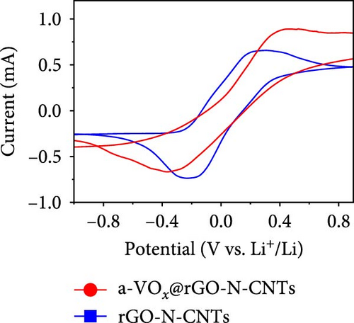
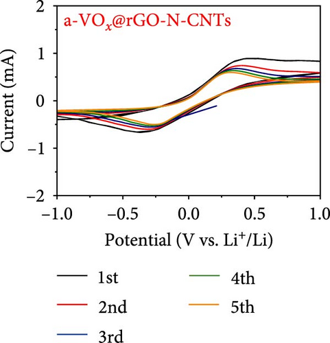
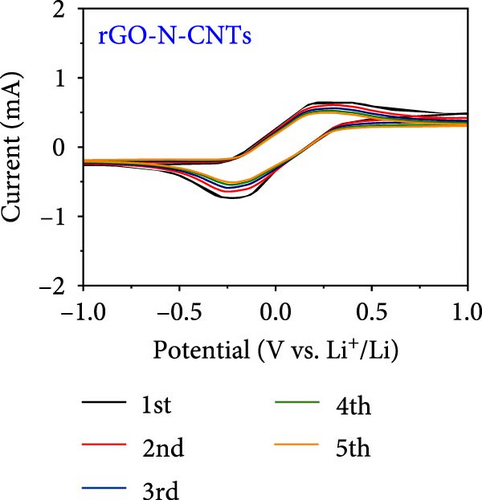
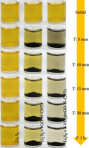
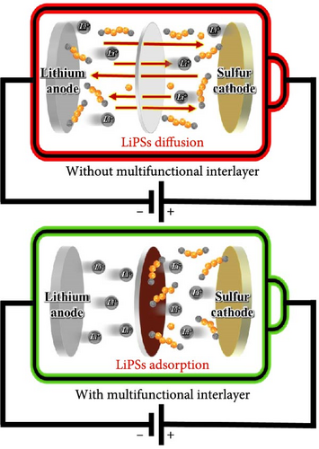
To further assess the effect of the catalytic conversion in restricting the diffusion of LiPSs, symmetric cells and visual examination tests were also conducted. Symmetric cells were constructed using the a-VOx@rGO-N-CNTs and rGO-N-CNTs electrodes as the counter and working electrodes and were filled with 20 µL of 0.33 M Li2S6 polysulfide solution. In Figure 7a, the initial CV curve obtained from a symmetric cell containing the a-VOx@rGO-N-CNTs electrodes shows a redox peak with an elevated current intensity owing to the effective electrocatalytic conversions of LiPSs due to the existence of a-VOx nanocrystals. Similar current intensities observed for the cell with the rGO-N-CNTs electrodes mainly arise from the effective physical trapping of LiPSs, facilitated by the extensive specific surface area of rGO-N-CNTs. Additionally, the metallic Co–Fe alloy in the host structure demonstrates electrocatalytic activity and offers a way of chemical immobilization. Moreover, overlapping CV curves of the cells with the a-VOx@rGO-N-CNTs (Figure 7b) and rGO-N-CNTs electrodes (Figure 7c) confirm the above results, indicating consistent electrocatalytic properties of these cells during cycling. These results were further validated by visual polysulfide capture tests, as shown in Figure 7d. Following the introductions of a-VOx@rGO-N-CNTs and rGO-N-CNTs powders into the polysulfide solution, digital photographs were captured at various time intervals. The a-VOx@rGO-N-CNTs powders exhibit a continuous color shift, transitioning from initial faded yellow (T = 0) to nearly transparent after 1 h (T = 1), contrary to the rGO-N-CNTs powders. This suggests efficient polysulfide capture in the cases of a-VOx@rGO-N-CNTs powders, ascribed to the existence of impregnated a-VOx particles as well as metallic Co–Fe alloy in the interconnected N-CNTs and rGO structures, which act as polar entities to chemically anchor LiPSs. A schematic diagram showing the synthesized a-VOx@rGO-N-CNTs powder as a functional interlayer is depicted in Figure 7e. The introduction of the coated separators not only overcomes the low electrical conductivity of the sulfur cathode but also ensures improved cell properties through the immobilization of LiPSs. The introduction of a functional interlayer, as indicated, ensures improved cell properties by trapping LiPSs toward the Li anode.
The improved trapping and faster electrocatalytic conversion of LiPSs by a-VOx@rGO-N-CNTs-coated separator, compared to the pristine separator, were further demonstrated by FE-SEM analysis of the separator’s morphology after disassembling the cell following 100 cycles at 0.5 C (Figure S14). Figure S14a,c presents FE-SEM images of a-VOx@rGO-N-CNTs-coated separator and the pristine separator before cycling, respectively. The images show that a-VOx@rGO-N-CNTs are uniformly coated over the entire separator (Figure S14a), while the pristine separator displays nanometer-sized open pores that allow Li-ion diffusion (Figure S14c). The FE-SEM image of a-VOx@rGO-N-CNTs-coated separator after cycling, shown in Figure S14b, demonstrates that the spherical morphology is retained, indicating the robustness of the nanostructure. Additionally, the absence of polysulfide deposits suggests that the polysulfide species were effectively converted by a-VOx nanoparticles and Co–Fe alloy. In contrast, the pristine separator (Figure S14d) shows significant polysulfide deposits due to the lack of material to trap LiPSs. This results in poor sulfur utilization and a significant degradation of electrochemical properties.
4. Conclusions
In this study, a-VOx@rGO-N-CNTs were proposed as functional interlayers for LSBs for the first time. Hierarchical framework composed of rGO and N-CNTs with high specific surface areas was not only advantageous for the physical absorption of LiPSs but was also effective in suppressing volume changes in the active material. Additionally, the uniformly grown N-CNTs afforded highly conductive pathways, promoting charge mobility and rapid redox reactions. Finally, the introduction of a-VOx nanoparticles into rGO-N-CNTs maximized the synergistic effect of rGO and the N-CNT framework that efficiently regulated the diffusion of LiPSs and elevated active material utilization by facilitating the conversion of LiPSs to elemental S. Assembled Li-S cell utilizing the a-VOx@rGO-N-CNT-coated separator demonstrates outstanding rate capability and stable cycling performance (an average discharge capacity loss of only 0.09% per cycle at 0.5 C after 400 cycles). Consequently, the design strategy proposed in this work provides valuable insights into the development of porous and conductive nanostructures for a wide range of energy storage applications including LSBs, while identifying the need for further advancements to achieve ultra-high sulfur loading mass (>5 mg cm−2) and ultra-low E/S ratios (<5 μL mg−1) for practical applications. This work establishes a foundation for future research dedicated to optimizing interlayer performance under these conditions, thereby facilitating progress toward the commercial implementation of LSB.
Conflicts of Interest
The authors declare no conflicts of interest.
Author Contributions
Kun Woo Baek and Sang-Hyun Kim contributed equally to this work. Prof. Gi Dae Park and Jung Sang Cho were co-corresponding authors in this work.
Funding
This work was supported by the National Research Foundation of Korea (NRF) (grant no.: RS-2023-00217581) and the Commercialization Promotion Agency for R&D Outcomes (COMPA) funded by the Ministry of Science and ICT (grant no.: RS-2023-00304768). Following are results of a study on the “Leaders in Industry-university Cooperation 3.0” project, supported by the Ministry of Education and the National Research Foundation of Korea. This research was supported by Chungcheongbuk-do Province and Convergence and Open Sharing System (COSS) Development Project (2023).
Supporting Information
Additional supporting information can be found online in the Supporting Information section.
Open Research
Data Availability Statement
The data used to support the findings of this study are included within the manuscript and the supporting information files.


