Energy-Efficient and Wide-Angle Simultaneous Wireless Information and Power Transfer for Smart Energy System
Abstract
This paper presents an energy-efficient and wide-angle simultaneous wireless information and power transfer (SWIPT) system designed for smart energy systems, such as the Internet of Things (IoTs). The system transmits information by connecting numerous IoT devices to a network, while a microwave-based power grid eliminates the need for manual battery replacement. Although the dual functionality of SWIPT, a communication signal chain and a power transmission chain, offers convenience, it increases the number of components and overall power consumption. A new energy-efficient architecture is proposed that shares the highest power-consuming component, the power amplifier-across both signal chains. The operating principle and theoretical analysis of the proposed architecture are presented, and improved power efficiency is demonstrated, achieving a DC-to-RF efficiency of 31.4%, which is more than double that of conventional architectures. Furthermore, a wide-angle scanning array antenna is developed, achieving scan angles up to ±79° in the xz-plane and ±75° in the yz-plane. The simultaneous transmission of power and 64-QAM modulated information signals is experimentally verified, maintaining error vector magnitude (EVM) below 8% across various distances and angles. With its energy efficiency and wide-angle capabilities, the proposed SWIPT system presents a practical solution for managing large-scale, spatially distributed IoT devices.
1. Introduction
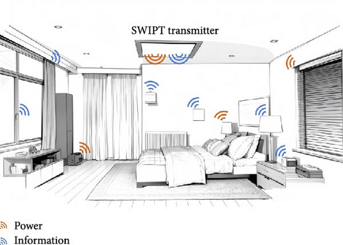
The rapid proliferation of smart energy systems, such as Internet of Things (IoTs) devices, has led to a growing demand for efficient network connectivity and power management. These devices are connected to a network via an access point (AP) and exchange essential information. However, many IoT devices still rely on traditional power management methods, such as battery replacement or wired power connections, which are labor-intensive and costly. Consequently, microwave-based wireless power transmission has emerged as a promising solution to reduce labor demands. As depicted in Figure 1, this concept has been expanded to simultaneous wireless information and power transfer (SWIPT) by integrating information communication and power transmission for IoT devices [1–9].
SWIPT, which combines a communication signal chain and a power transmission chain, offers significant convenience. The conventional SWIPT AP, as shown in Figure 2a, consists of an RF power transmission chain (comprising an oscillator, drive amplifier, and high-power amplifier [HPA]) and a communication circuit (comprising a mixer, drive amplifier, and power amplifier) for information transmission [10]. However, this architecture, which separates the power and information chains, requires numerous components and suffers from low overall efficiency, limiting the practical feasibility of SWIPT systems. In particular, the power amplifier is the most energy-consuming component among RF circuits. As the number of amplifiers increases, power consumption rises accordingly, reducing the overall system efficiency. This challenge motivates the development of more efficient SWIPT systems with enhanced practical applicability. This necessitates the development of a new energy-efficient architecture.
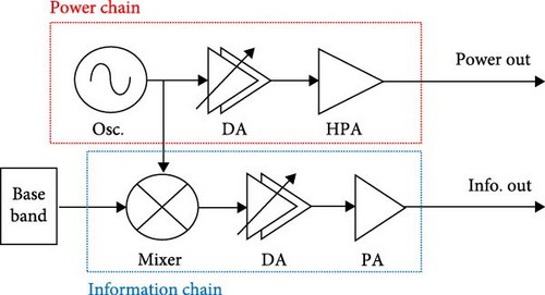
As shown in Figure 2a, the signal generated from the oscillator is amplified by the drive amplifier. Then, high-power RF signals are output from the HPA. To compare the energy efficiency of the architectures, the DC-to-RF efficiency (ηDC-RF = PRF/PDC) is adopted as the conversion efficiency of the supplied DC power to the RF power output [11, 12]. If the transmitter has low ηDC-RF, most of the DC power is lost as thermal energy. Therefore, a new architecture with high ηDC-RF is essential for an energy-efficient system.
Even if both information and power signals are well generated, a wide-angle phased array antenna is required to provide power to spatially distributed IoT devices [13–23]. Various methods have been presented for wide-angle coverage: [13] used beam-tilting to cover wide angles by selecting a tilted beam facing the scanning direction and reconstructing the beam pattern to create a wide-angle beam; another method [14] combined main beams with multiple angles and physically integrated them for wide-angle convergence. However, existing studies still have narrow angles, and array antennas with wider angles are required. Addressing this need provides a second design objective: the development of a SWIPT system capable of serving a wide spatial range. The state-of-the-art research will be compared with the wide-angle array antenna proposed in section IV.
- 1.
A novel energy-efficient architecture is proposed that shares the power amplifier, the component with the highest power consumption, across both the information and power chains.
- 2.
The operating principle and theoretical analysis of the proposed architecture are presented, demonstrating better power efficiency than conventional architecture.
- 3.
A wide-angle antenna array is also introduced, which shows a wider scanning performance compared to existing studies.
- 4.
In addition, the proposed SWIPT system through received power and error vector magnitude (EVM) is demonstrated in experiments of simultaneous transmission of information and power.
- 5.
Given its energy efficiency and wide-angle capabilities, the proposed SWIPT system is poised to be an effective solution for managing a large number of widely distributed IoT devices.
The rest of this paper is organized as follows: Sections 2 and 3 introduce the proposed method and materials for the energy-efficient and wide-angle SWIPT system. Section 2 presents the energy-efficient SWIPT architecture and compares its power efficiency with that of conventional architectures following a theoretical analysis. Section 3 introduces an antenna structure and transmitter designed for wide-angle SWIPT. The methods and materials presented in Sections 2 and 3 are validated in Section 4. The SWIPT system is implemented, and its wide-angle performance is compared with that of conventional studies. Finally, the discussion and conclusion of this work are given in Section 5.
The aim of this research is to develop an energy-efficient and wide-angle SWIPT system suitable for smart energy systems, such as IoT networks. Specifically, we propose a novel SWIPT architecture that shares the power amplifier between the information and power chains to enhance energy efficiency, and introduce a wide-angle antenna array to support spatially distributed IoT devices. The effectiveness of the proposed system is validated through theoretical analysis and experimental results.
2. Energy-Efficient SWIPT
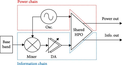
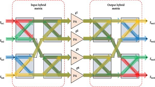
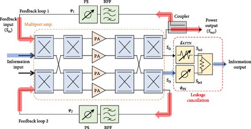
In conventional SWIPT architecture, as illustrated in Figure 2a, the information and power chains are independently configured, with HPAs employed in both chains. However, the proposed architecture deviates from this by allowing the power and information chains to share the HPA. This results in the generation of high output power and gain, eliminating the need for a drive amplifier in the power chain, thereby reducing power consumption. This section presents a method for achieving energy-efficient SWIPT.
2.1. Operating Principle
2.2. Performance
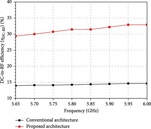
To compare the energy-efficient performance of the proposed architecture with conventional architecture, the DC-to-RF efficiency is calculated. The efficiency of the architecture is evaluated with commercially available parts. As shown in Figure 2, in the conventional and proposed architectures, the oscillator, drive amplifier, power amplifier, and HPO are used as HMC431, HMC407, HMC1121, and HMC7357, respectively. Since the proposed architecture eliminates the need for a separate drive amplifier, it reduces overall power consumption. As shown in Figure 4, the proposed architecture achieves higher DC-to-RF efficiency than the conventional design. At a center frequency of 5.8 GHz, the conventional and proposed architectures achieve DC-to-RF efficiencies of 14.2% and 31.4%, respectively.
Despite generating energy-efficient signals, high isolation is necessary because communication performance degrades when interference occurs between information and power signals. Therefore, the proposed architecture incorporates a leakage cancelation circuit, as shown in Figure 3b, to ensure high isolation. The leakage signal can be canceled by combining two information output ports with a phase difference of 180°.
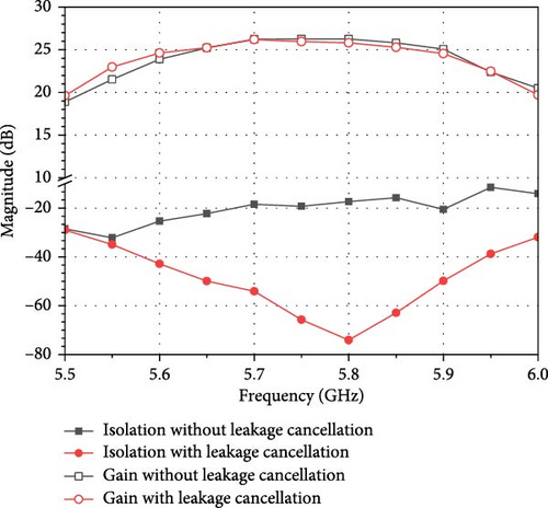
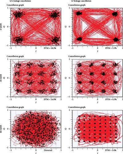
Figure 5a shows the gain and isolation performance with and without leakage cancelation. At 5.8 GHz, the gain is 26.26 dB without leakage cancelation and 25.80 dB with it. Additionally, the isolation improves from 17.34 to 74.05 dB with leakage cancelation. It has 56.71 dB of improved isolation without gain degradation. Figure 5b compares measured EVM without and with proposed leakage cancelation. The proposed architecture with leakage cancelation also demonstrates improved EVM performance. The EVM for different modulation schemes shall be better than the limits in 3GPP TS 36.104. 3GPP requires 16 and 64-QAM at 12.5% and 8%, respectively. The proposed system not only achieves higher efficiency than conventional approaches but also satisfies the required EVM thresholds. The proposed method improves 16-QAM with 14% EVM and distorted 64-QAM signals with EVM of 4.5% and 3%, respectively. Therefore, the proposed architecture is both energy-efficient and provides high isolation. The proposed architecture in the following section is still used.
3. Wide-Angle SWIPT
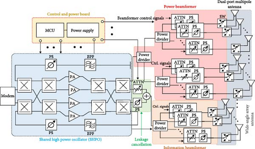
This section presents the methods and materials for wide-angle SWIPT, including the method introduced in Section 2. The transmitter, which employs the proposed architecture, is composed of the SHPO, a leakage cancelation circuit, a control/power board, power/information beamformers, and a wide-angle array antenna, as illustrated in Figure 6. As discussed in Section 2, the SHPO utilizes an MPA and feedback loops to generate high-gain signals in an energy-efficient manner. Subsequently, the information signal mitigates interference from the high-power signal using a leakage cancelation circuit. This section covers the power/information beamformers and wide-angle array antennas. The power/information beamformers are designed for 2D wide-angle beamforming. A wide-angle array antenna is configured in line with the proposed antennas and is connected to a feeder network for 2D beamforming.
Despite the energy efficiency of SWIPT, limited scan angles can prevent power delivery to widely distributed IoT devices. A wider scan angle than those in conventional studies is demonstrated in the 2D plane using the new wide-angle SWIPT technology. The array beam pattern for SWIPT is formed as the product of the beam pattern of a single antenna and the array factor [31]. Therefore, achieving wide-angle SWIPT requires a broad beam pattern from each individual antenna element. A multipole antenna with a compact and low-profile structure is designed in this study. Multipole antennas allow the split conductors of a single antenna to form two or more poles, thereby flexibly determining the direction of the current loop [32]. This current diversity allows the antenna to form a wide beam pattern.
Conventional array methods connect an RF chain to each antenna to achieve 2D scanning, which incurs high costs. Alternatively, 1D scanning can be performed using a sub-array. A dual-port multipole antenna is proposed to achieve 2D scanning while using sub-arrays, as shown in Figure 7a. A switched feeder network, which is connected to each of the antenna’s dual ports, is designed to support 2D scanning as shown in Figure 6. After selecting the desired scanning plane via switch operation, a power/information beamformer-comprising a phase shifter, attenuator, and power amplifier-is connected. A microcontroller unit (MCU) controls beamformer operation. Conventional sub-array methods require 16 RF chains to operate an 8 × 8 phased array with 2D scanning, whereas the proposed approach reduces this to just 8 RF chains.
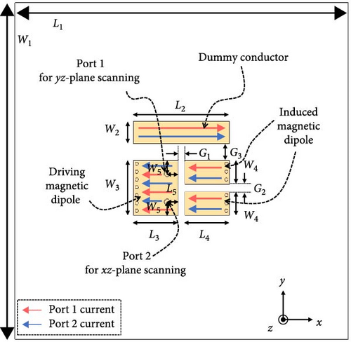
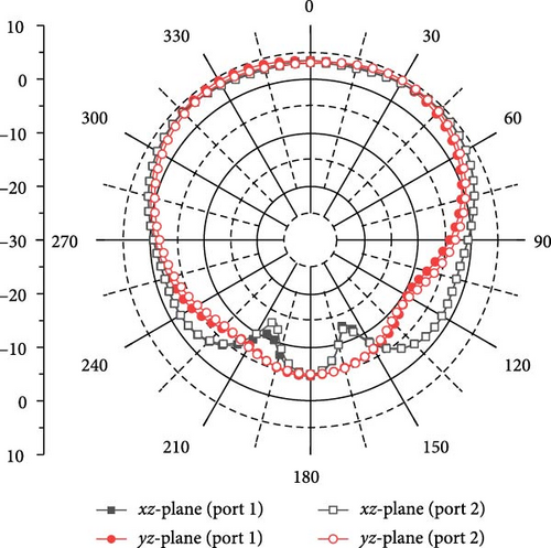
Figure 7a illustrates the structure and current distribution of the dual-port multipole antenna. The dimensions of the antenna were optimized as listed in Table 1. The proposed antenna comprises a driving magnetic dipole, two induced magnetic dipoles, and an induced conductor. Unlike patch antennas that generate current in a single direction, the proposed design supports multidirectional current flow, enabling wide beam formation. As a result, the half-power beamwidth (HPBW) in the xz-plane and yz-plane from port 1 measures 154.9° and 134.9°, respectively, with a peak gain of 4.22 dBi. Similarly, the HPBW from port 2 is 153.9° in the xz-plane and 131.9° in the yz-plane, accompanied by a peak gain of 4.33 dBi. Both ports exhibit similar radiation patterns based on the same underlying principle, as shown in Figure 7b.
| Parameter | mm | Parameter | mm | Parameter | mm |
|---|---|---|---|---|---|
| L1 | 60 | L5 | 2 | W4 | 4.2 |
| L2 | 17.34 | W1 | 60 | W5 | 2.4 |
| L3 | 8.07 | W2 | 4 | G1 | 1.2 |
| L4 | 8.07 | W3 | 9.8 | G2 | 1.4 |
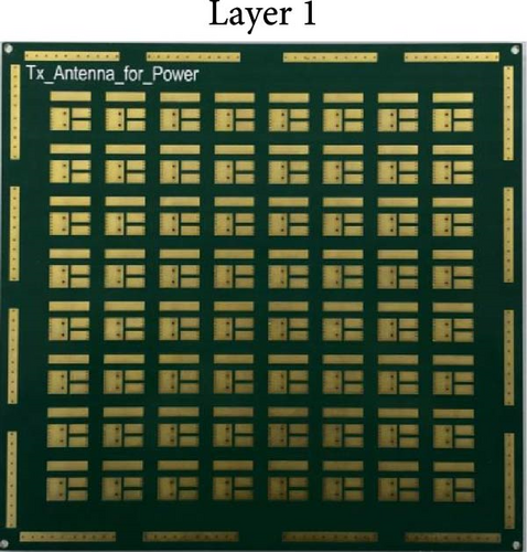
As shown in Figure 8a, the dual-port multipole antenna array is designed and implemented as an 8 × 8 array, where the array antenna has dimensions of 4.25 × 4.25 × 0.02 λ0 at a center frequency of 5.8 GHz. The array antenna using a dual-port multipole antenna for a wide scan angle is introduced in detail in the next section.
4. Implementation and Experiment
In this section, the SWIPT system is verified by the method proposed in the previous sections. For verification, the SWIPT system is implemented and measured in the subsection below.
4.1. SWIPT System Implementation
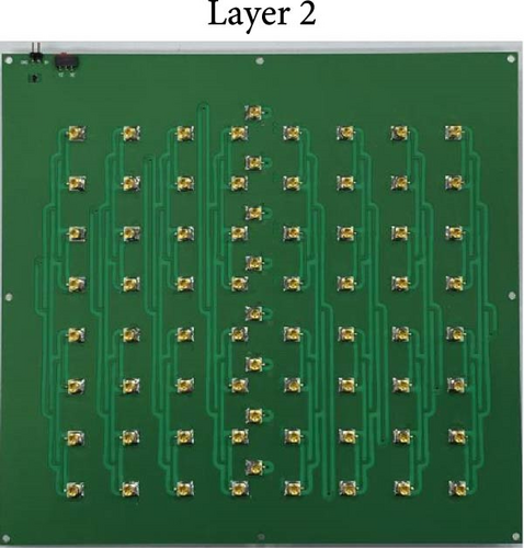
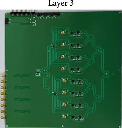
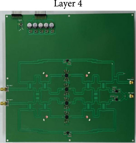
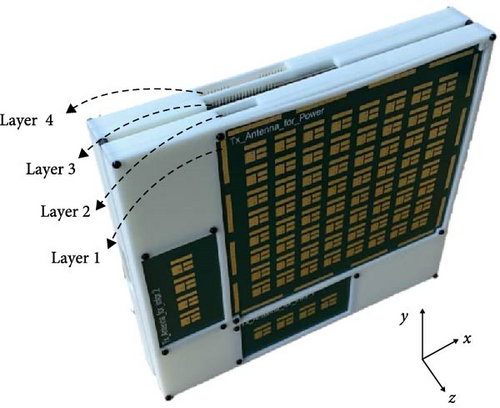
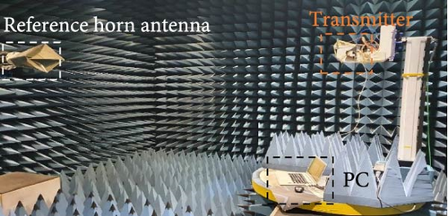
The SWIPT transmitter proposed in Figure 6 is implemented as shown in Figure 8a–e. The 8 × 8 wide-angle array antenna (Figure 8a) is mounted on the front of the SWIPT transmitter, as shown in Figure 8e. In the second layer, a feeder network connecting the beamformer and antenna is integrated. The beamformer with 8 RF chains includes a phase shifter and attenuator and is connected as a third layer. Finally, the SHPO consists of a 4 × 4 MPA, a feedback circuit, and a leakage cancelation circuit. These four layers are interconnected through SMP-type connectors and packaged into a case fabricated by a 3D printer. Additionally, two 4 × 1 array antennas are connected to the output of the leakage cancelation circuit for information transmission. The antennas use the same design and maintain the same element spacing as the power array. As depicted in Figure 8e, the antennas are arranged for information transmission in both the xz-plane and the yz-plane. Figure 8e shows the prototype of the proposed SWIPT transmitter, which is used to measure wide-angle performance. An anechoic chamber and a reference horn antenna were used as shown in Figure 8f.
4.2. Wide-Angle Performance Measurement
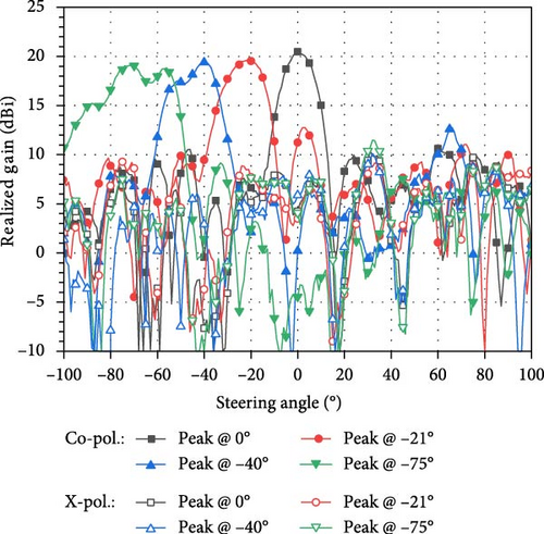
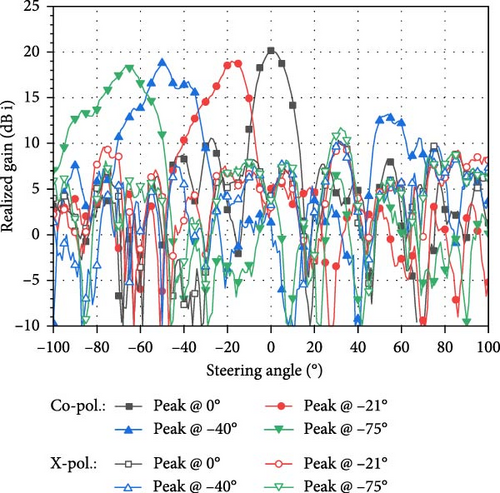
To evaluate the performance of the wide-angle array antenna, a beamformer with 8 RF chains is connected. Using an RF switch, the xz- and yz-planes are electronically steered and measured. As shown in Figure 8g,h, the array antenna achieves a maximum gain of 20.5 dBi. The symmetrical scan range reaches ±79° in the xz-plane and ±75° in the yz-plane, based on a 3 dB gain drop.
Table 2 compares state-of-the-art wide-angle array antennas, including this work. [17–19] achieved wide-angle scanning using a single wide-angle antenna. [17] implemented wide-angle scanning using a magnetic dipole with a wide angle. In [18], wide-angle scanning was achieved by removing inherent coupling using the coupling-cancelation method. [19] created the desired pattern by using reflection-canceling vias and phasing elements to obtain a tapered distribution in amplitude and phase, thereby achieving wide-angle scanning. [20, 21] presented a wide-angle scanning method based on a conformal array antenna. [20] achieved a wide-angle scanning performance similar to that of a conformal array antenna by using high-low alternate elements to proactively modulate the array aperture. In [21], a planar pseudo-conformal array antenna that mimics a wide-angle conformal array was proposed. [22, 23] achieved wide-angle scanning using a lens. [22] is a hemispherical lens fed by a patch phased array antenna with eight scanning angles simply achieved wide-angle scanning. Although [23] did not perform beam scanning with electronic control, it had a high gain and the widest scan angle among the references through a lens array with a waveguide feeder. In Table 2, this work shows a novel wide-angle array antenna that has the widest scan angle when compared to the most recent wide-angle array antennas.
| Ref. | Year | Number of element | Aperture size (λ0× λ0) | Measured scan angle (°) @ gain variation | Peak gain (dBi) | Key technology |
|---|---|---|---|---|---|---|
| [24] | 2019 | 4 × 4 | 2.98 × 2.19 | −60 to +60 @ 3 dB | 13.0 (mea.) | Wide-angle single antenna |
| [25] | 2022 | 4 × 4 | 3.2 × 1.8 | −60 to +60 @ 3 dB | 14.2 (mea.) | Wide-angle single antenna |
| [26] | 2022 | 16 × 12 | 13.18 × 9.07 | −60 to +60 @ 3 dB | 14.8 (mea.) | Wide-angle single antenna |
| [27] | 2023 | 4 × 6 | 5.63 × 1.88 | −60 to +60 @ 3 dB | 15.5 (mea.) | Conformal array antenna |
| [29] | 2023 | 1 × 4 | 1.93 × 3.13 | −62 to +62 @ 3 dB | 15.2 (sim.) | Conformal array antenna |
| [30] | 2019 | 8 × 1 | 4.67 × 2.55 | −63 to +63 @ 5 dB | 14.0 (mea.) | Lens antenna |
| [31] | 2023 | 1 × 4 | 1.4 × 8 | −70.8 to +70.8 @ 3 dB | 20.3 (mea.) | Lens antenna |
| This Work | 2024 | 8 × 8 | 4.25 × 4.25 | −79 to +79 @ 3 dB in xz-plane | 20.5 (mea.) | Wide-angle single antenna |
| −75 to +75 @ 3 dB in yz-plane |
4.3. SWIPT Experiment
Figure 9a illustrates the experimental setup for evaluating the performance of the proposed SWIPT system in an anechoic chamber. This setup includes the proposed SWIPT transmitter, a universal software radio peripheral (USRP), receiving antennas for power and information, and a spectrum analyzer. The receiving antenna is a single patch antenna operating at 5.8 GHz with a gain of 6 dBi, as shown in Figure 9a. The received power and EVM are measured based on the scan angle. As a result, the proposed SWIPT transmitter can simultaneously transmit both information and power. This implies that the array antennas for power and information are operating concurrently.
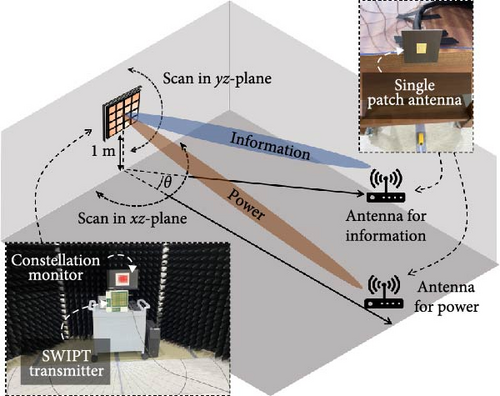
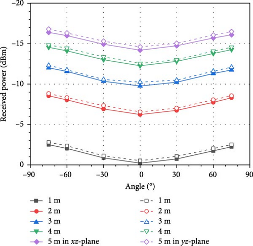
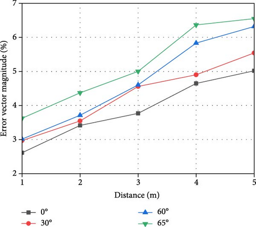
The receiving antennas for power and information, which are single patch antennas operating at 5.8 GHz, are positioned separately. These single patch antennas have a gain of approximately 6 dBi at 5.8 GHz. As shown in Figure 9b, measurements were taken at five distances (1, 2, 3, 4, and 5 m) and seven scan angles (−75°, −60°, −30°, 0°, 30°, 60°, and 75°) in both the xz-plane and yz-plane. As expected, received power decreases with increasing distance and scan angle. A 64-QAM modulated signal is delivered to the antenna for information, as shown in Figure 9c. The EVMs are measured at five distances (1, 2, 3, 4, and 5 m) and four scan angles (0°, 30°, 60°, and 65°). The received power decreases as the distance and scan angle increase, leading to a higher EVM. Nevertheless, the results demonstrate that the EVM remains within 8%. The variation in received power and EVM with respect to the scan angle is small because the proposed SWIPT transmitter has a wide angle.
The experiment proves that the proposed SWIPT system, while being energy-efficient and wide-angle, can transmit information and power simultaneously. The main contributions of this study are: Efficiency has been improved with a new architecture for SWIPT, and the dual-port multipole antenna array has the widest angle in the 2D plane. Future research is expected to explore the SWIPT transmitter along with energy-efficient relaying networks, new access technologies, etc. [33–35].
5. Conclusion
This paper has presented an energy-efficient and wide-angle SWIPT system designed to address the challenges of high power consumption and limited spatial coverage in conventional architectures. The proposed architecture improves energy efficiency by sharing the power amplifier, the most power-consuming component, across both the information and the power signal chains. This novel approach was theoretically analyzed and shown to outperform conventional designs in terms of power efficiency. Another critical issue addressed in this study is the distortion of information caused by strong power transmission. By applying a leakage cancelation circuit, the interference was successfully suppressed, enabling stable and isolated information transfer. This improvement was confirmed through enhanced EVM performance. To support wide-area IoT applications, a dual-port multipole antenna was designed, achieving broad beam patterns in both the xz- and yz-planes. Moreover, by incorporating an RF-switch-based scanning method, the system reduced the number of required RF chains-halving the hardware complexity compared to conventional sub-array approaches. The proposed system was implemented as an 8 × 8 transmitter array, composed of the antenna, feeder network, beamformer, and SHPO. Measurements conducted in an anechoic chamber demonstrated the widest scan angles reported to date, along with effective simultaneous transmission of information and power over long distances and wide angles. In conclusion, the proposed SWIPT system enhances energy efficiency, ensures robust signal integrity, enables wide-angle transmission, and reduces hardware complexity. These contributions position the system as a practical and scalable solution for next-generation IoT deployments.
Conflicts of Interest
The authors declare no conflicts of interest.
Author Contributions
Sol Kim is the first author.
Funding
This work was supported in part by the Institute of Information & Communications Technology Planning & Evaluation (IITP) grant funded by the Korea Government (MSIT) (Grant RS-2024-00395702, Development of Envelope Tracking PAM for Sub-6 GHz Massive MIMO Supported Base Stations) and in part by the National R&D Program through the National Research Foundation of Korea (NRF) funded by the Ministry of Science and ICT (Grant 2021M3H2A1038042).
Open Research
Data Availability Statement
The data used to support the findings of this study are available from the corresponding author upon request.


