STATCOM and DFIG Reactive Power Management Strategy for LVRT Capability Enhancement Under Asymmetrical Grid Faults
Abstract
In the trajectory of carbon dioxide (CO2) neutrality, wind and solar energies will be the key for the energy transition in the electricity sector; however, a massive integration of solar and wind farms into the electricity grid by 2050 will be carried out. For this end, powers control and powers management of these two renewable energies have taken the attention of several researchers since the last decades. This article presents a reactive energy management strategy for a power grid linked to a wind farm utilizing doubly fed induction generators (DFIG) and enhanced by a static reactive power compensator (STATCOM). This management strategy improves an electrical grid capability in the event of a low-voltage ride through (LVRT) and aims to optimize the sizing of the STATCOM to be installed alongside the wind farm. The proposed oriented voltage control strategy (VOC) for the grid-side converter and STATCOM facilitates effective reactive current injection into the grid during symmetrical faults with significant voltage sags. A maximum power point tracking (MPPT) approach combined with stator flux-oriented control (FOC) applied to the rotor side converter enables effective control of the DFIG during an asymmetrical fault. Breaking down currents and voltages into positive and negative sequences expressed in the synchronous frame enhances DFIG and STATCOM control during grid voltage asymmetrical faults. The control algorithms are validated by simulation results using MATLAB-SIMULINK.
1. Introduction
Most countries’ grid codes mandate that wind energy conversion systems maintain a continuous connection to the electrical grid, even under various conditions. These systems are required to contribute to network stability by managing the transfer of active and reactive power. In the event of grid voltage faults, priority is given to reactive power control to minimize voltage drops at the point of common coupling (PCC) and to maintain the voltage at its nominal level. The reactive current control related to the negative sequence, which must be injected by a wind turbine with a full-scale converter during a grid voltage asymmetrical fault, is discussed in [1] to mitigate the negative component of the PCC voltage. In this reference, authors demonstrate how to calculate the angle of the negative voltage sequence, methods for limiting currents of the converters and strategies for restoring PCC voltage after fault clearance. In reference [2] the authors propose a control method utilizing the normalized maximum correntropy criterion (NMCC) to minimize torque, active and reactive power ripples produced by wind system based DFIG and integrated with a photovoltaic generator during a non-ideal electrical grid operation. This strategy ensures sinusoidal grid currents and eliminates rotor currents distortion even with nonlinear loads connected at the PCC point. In paper [3], a modified control strategy employing the SVPWM technique is applied to the DFIG grid-side converter (GSC), effectively eliminating current harmonics caused by nonlinear loads. The GSC control is modified to provide active filtering of current harmonics, ensuring the quality of electrical energy. In manuscript [4], a novel coordinated control strategy is applied to the DFIG GSC and RSC converters ensuring that the reactive current of both the negative and positive sequences meet the grid code requirements. This strategy is based on the VOC command utilizing positive and negative sequences decomposition to enhance DFIG’s LVRT capability. Tobias et al. [5] presents a comparison between the VOC control with positive and negative sequence separation and the control without sequences separation applied to the converters of a high voltage direct current transmission, specifically in the context of asymmetric grid faults. This study demonstrates the superiority of the VOC control with positive and negative sequences separation over the conventional VOC control. The control of active and reactive power transfer between a DFIG and the grid in the case of a voltage rise is investigated by authors of the paper [6]. This article addresses the coordination of active and reactive power generated by the DFIG to enhance the high voltage ride through capability of the electrical network utilizing a model predictive control strategy. In [7], authors developed a control strategy based on invasive weed optimization (IWO) that enables DFIG speed control without the use of speed sensors addressing both balanced and unbalanced grid faults. The authors demonstrated the advantages of the (IWO) method over the neuro-fuzzy-adaptive method (AN-FIS) and the artificial neural network method for various DFIG speeds. In reference [8], the searching space minimization-based particle swarm optimization (SSM-PSO) method was developed and compared to the classic P&O method for maximum power point tracking (MPPT) of a wind turbine using a DFIG machine. The reference speeds of the wind turbine speed regulation loop are generated using the (SSM-PSO) method which is insensitive to wind speed variations. In reference [9], the authors proposed three methods for controlling the reactive power of a wind farm based on a DFIG aiming to enhance power transfer in a weak grid. The three methods are based on: adjusting the grid power factor, controlling the grid voltage using only grid side converter (GSC), and controlling the grid voltage control using both the GSC and the rotor side converter (RSC). The transient stability of an electrical grid connected to a wind farm based on a DFIG is exanimated in [10]. In this paper, the authors demonstrated the impact of reactive power injected by the DFIG into the network on both voltage amplitude and phase. In manuscript [11], the constraints on the rated currents of the GSC and GSR of the DFIG, as well as the limitations related to modulation saturation in accordance with the DFIG P–Q curve are discussed and addressed to improve the wind turbine’s P–Q generation capability. The introduction of a gain matrix in the PLL regulation loop, used in the DFIG control blocks during abnormal grid operations, enables stable operation and enhances the phase margin of the PLL, as developed by Bin et al. [12]. To prevent synchronization losses in a DFIG-based wind turbine during severe grid faults, the authors of paper [13] proposed an algorithm to reduce active power oscillations during grid faults, ensuring transitional stability of the network. In article [14], a DFIG control strategy based on small signals is proposed to enhance wind turbine operation during power grid faults. This strategy considers three factors: the stability and capacity of the DFIG as well as the grid code requirements regarding the exchange of active and reactive power. All the references mentioned above focus on the development of DFIG converter control strategies (GSC and RSC) aimed at ensuring the stable operation of both the grid and the wind turbines during grid faults. Other approaches utilize static synchronous reactive power compensators (STATCOM) as effective solutions for rapid control of grid voltage, frequency, and powers during grid faults. In manuscript [15], a dynamic control approach for-grid voltage is explored, focusing on eliminating its negative sequence and maintaining a balanced network even in the event of severe faults. This approach involves transferring the appropriate active power from the negative sequence to the positive sequence, which helps suppress the grid’s reverse voltage by injecting the necessary reactive current. To enhance the speed response to voltage dips in a hybrid system comprising a DFIG and a photovoltaic generator, the authors of paper [16] employed a static synchronous compensator (STATCOM) at the PCC with the electrical grid. The STATCOM is controlled using a strategy that employes a fuzzy logic controller. In paper [17], a reactive energy compensation system is proposed, consisting of a fixed capacitor and a STATCOM, to enhance the quality of electrical energy during grid voltage faults.
- •
The STATCOM provides reactive power support for a DFIG-based wind turbine which has a limited capacity for reactive energy production.
- •
The grid manager has three options for controlling reactive current: through the wind turbine, through the STATCOM, or through both simultaneous.
- •
The size and power of STATCOM are reduced compared to a standalone STATCOM, as it shares reactive power responsibilities with the wind farm.
- •
During low wind speeds and grid voltage faults, wind turbines absorb reactive power to create their magnetic field, while the STATCOM supplies the necessary reactive power to the electrical grid.
- •
During medium and high wind speeds, and in the event of grid voltage faults, the STATCOM produces all the required reactive power, as long as it does not exceed its reactive capacity. If the required reactive power surpasses the STATCOM’s maximum capacity, the excess reactive power will be generated by the wind farm.
- •
A STATCOM enables a very fast response time to supply reactive power during grid voltage faults.
The validity and effectiveness of the proposed method are tested and validated by simulation using MATLAB/SIMULINK.
- -
Section 2 presents the structure of the wind energy conversion system based on a DFIG, connected to the electrical grid and supported by a STACOM for reactive power support.
- -
The first part of Section 3 is dedicated to the requirements of the Tunisian electrical grid concerning the operation of wind farms during power grid faults. The second part of this section presents the flowchart for reactive power management among the power grid, STATCOM and the wind farm.
- -
Section 4 is dedicated to the modeling of the DFIG in the (dq) axis frame in case of asymmetrical grid voltage faults.
- -
The GSC, RSC, and STATCOM converters control strategies are developed in Section 5 in the event of asymmetrical grid voltage faults.
- -
Section 6 provide the simulation results accompanied by detailed interpretations and discussions
- -
Finally, Section 7 gives a general conclusion of this paper.
2. STATCOM-WECS System Design
Since the 1990s, Tunisia has implemented a strategy to develop wind energy. During the initial phase, small-power wind turbines were installed to meet the energy needs of scattered rural households. In 2000, the country installed its first large-scale wind power plant, with a capacity of 10 megawatts (MW). The success of this project encouraged the Tunisian Electricity and Gas Company (STEG) to expand its wind energy portfolio. In 2009, the first wind farm was established in Sidi Daoud, with a total capacity of 55 MW. Following this, a second wind farm was developed in the Bizerte region, spanning two locations. These sites have respective capacities of ~97 and 93 MW, comprising a total of 143 wind turbines. This marks a significant step toward increasing the share of renewable energy in electricity production, from around 3% in 2013 to a target of 30% by 2030. The connection of wind turbines to the Tunisian grid can lead to operational disturbances that may have significant consequences on the electrical network. Installing a STATCOM at the PCC with the wind farm can help mitigate these disturbances and enhance the stability of the grid.
The diagram in Figure 1 illustrates the wind energy conversion system (WECS) supported by a STATCOM, connected to the electrical grid at the PCC. The DFIG-based WECS and STATCOM are coordinated to supply the required reactive power and enhance the power grid’s LVRT capability.
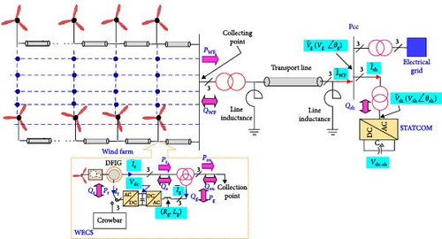
The crowbar is used to protect the rotor and power converters from current overshoots during grid faults. It is activated when either rotor current Ir or DFIG DC voltage Vdc exceed, respectively, rotor current limit Ir−Lim and DFIG DC voltage limit Vdc−lim [21, 22]
3. Tunisian Electrical Grid Requirements and Reactive Power Management Flowchart
3.1. Tunisian Electrical Grid Requirements
- •
WECS must remain connected to the electrical grid under specific voltage dip levels.
- •
WECS must dynamically provide the required reactive power based on the voltage drop.
- •
Wind turbines must quickly restore their active power production after the voltage fault is cleared.
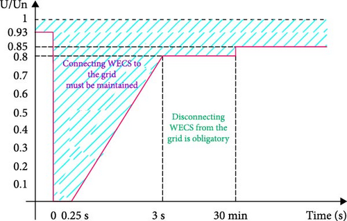
Figures 2 and 3 illustrate the following characteristics, respectively: WECS operating time as a function of voltage drop, and the reactive current injected/absorbed by a WECS in relation to grid voltage variation as specified by the Tunisian grid code [23].
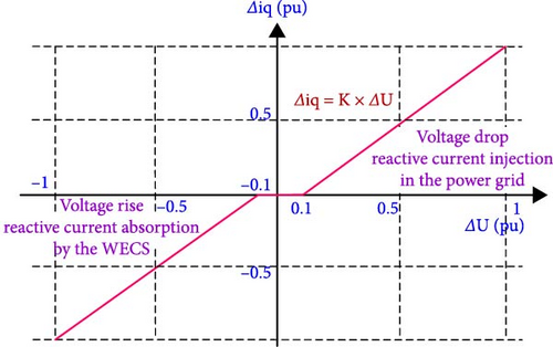
The coefficient k, determinated by the grid operator, is set between 0 and 10 pu.
The WECS operating points must be located in the hatched area.
Figure 2 illustrates that a wind energy conversion system must remain connected to the Tunisian power grid during a short circuit lasting 0.25 s and during a voltage drop to 0.8 pu for 30 min. Additionally, if the voltage drop stays above 0.85 pu, the wind farm must remain connected to the grid.
Figure 3 presents the values of reactive currents that a wind farm must inject or absorb during voltage drops or increases, depending on the magnitude of the voltage fluctuations. The figure also indicates that when the network’s voltage variation does not exceed 0.1 pu, the wind turbines do not exchange reactive power with the electrical grid.
The WECS connected to the Tunisian grid is required to produce or absorb reactive power in proportion to the active power it supplies. Figure 4 defines the limits for reactive power of a WECS based on its active power output. This figure also demonstrates that the reactive power exchanged with the electrical network does not exceed one-third of the active power supplied by the wind turbines, while maintaining a power factor above 0.95. This limitation on reactive power highlights the importance of installing a STATCOM at the connection point of the wind farms.

3.2. Reactive Power Management Flowchart
Wind farms utilizing doubly-fed induction generators are sensitive to disturbances in the electrical grid due to the direct connection of their stators to the grid through transformers. Moreover, because wind speed fluctuates over time, the installation of STATCOMs at the connection points between these wind farms and the electrical networks becomes necessary to stabilize the system. Reactive energy management between the electrical grid, STATCOM, and the wind farm is a crucial factor for enhancing the operating efficiency of the electrical system. It enables the rapid elimination of faults and ensures a swift recovery to a stable state of the grid [22, 24]. Figure 5 presents a flowchart outlining the reactive energy management process for the electrical system, considering the preferences set by the grid manager.
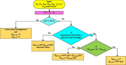
By measuring the active and reactive powers at the PCC, the power supplied by the wind turbines, the power provided by the STATCOM, the RMS voltage at the PCC, the power factor, and the grid frequency, we can effectively control the management of reactive power between the STATCOM, the WECS, and the grid. If the voltage drop at the PCC exceeds international standards, the grid operator may require a specific reactive power to be injected or absorbed by the electrical grid, a mode known as reactive power control. The second control mode involves adjusting the reactive power in response to voltage variations at the PCC, which is referred to as voltage control. The reactive power control flowchart must be integrated with the active power control flowchart to ensure that the voltage amplitude and frequency of the grid remain within international standards because adjusting reactive power influences active power variation to maintain a power factor greater than 0.95 and keep the frequency at its nominal value.
where QWF, Qsh, Qr are, respectively, wind farm reactive power, STATCOM reactive power, and requested reactive power. QWF_ref is the reference reactive power to be supplied by the wind farm, it is equal to the sum of the reference reactive powers delivered by each wind turbine n is the number of wind turbine.
4. DFIG Modeling under Asymmetrical Grid Voltage Faults
During an unbalanced fault in the electrical grid, a negative sequence voltage can arise, potentially causing malfunctions in the connected wind turbines, particularly in DFIG-based wind turbines whose stators are directly connected to the grid through transformers. This negative sequence voltage induces negative current in both the stator and rotor of the machine, leading to fluctuations in torque, active and reactive power, as well as instability in the DC bus connecting the wind turbine’s two converters. As a result, excessive stator and rotor currents can occur, potentially damaging the machines, while the increased DC bus voltage may destroy the RSC and GSC converters. One of the most common solutions to ensure the wind conversion system operates safety under unbalanced conditions is to eliminate the negative sequence in the stator and rotor currents.
During an unbalanced grid fault, the DFIG generator is governed by the following equations, expressed in the positive-sequence synchronous rotating (d, q) reference frame.
p is the DFIG pair of poles.
Equations (9) and (11) demonstrate that during a voltage imbalance, there was an appearance of oscillatory terms at the torque and power levels. So, to improve the performance of DFIG under these conditions, these terms must be canceled.
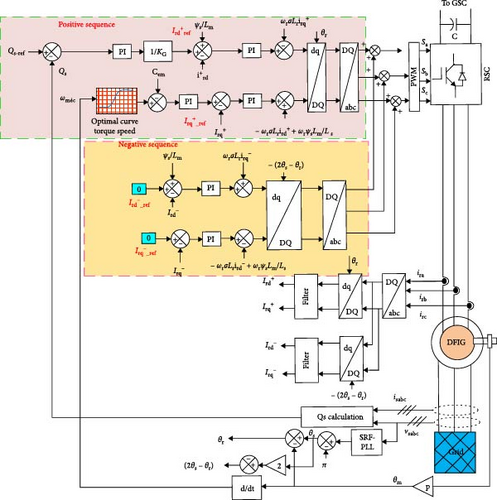
From Equation (15), we can design the rotor current controllers. By considering the coupling terms represented in red in the rotor voltage equations, we can control each of the voltage independently. This allows for the separate control of the active and reactive powers of the positive and negative sequences. represent the reference rotor voltages to be applied to the RSC converter in order to achieve the desired DFIG currents.
5. Control System under Asymmetrical Grid Voltage Faults
In the event of asymmetrical voltage faults, decomposing the control strategy into two sequences, referred to as the positive sequence and the negative sequence, can enhance the performance of the WECS and STATCOM controls. The goals of this decomposition are to extract the direct three-phase voltages system from the reverse voltages and to eliminate the negative sequence currents. The currents and voltages are represented in the synchronous frame rotating at the ωs speed. The direct and reverse reference currents of the positive sequence are selected similarly to how they are in the case of symmetrical faults [25]. The reference currents for the negative sequence are set to zero to cancel their effects. Voltage-oriented control (VOC) is a widely applied control strategy for power converters, especially in maintaining the stable and efficient operation of complex industrial systems, even under severe electrical network faults. By using the Park transformation, unbalanced currents and voltages are converted from the stationary reference frame (abc) into a rotating reference frame (dq) at the grid frequency. This transformation allows the direct (positive) sequence components of the system to be converted into DC (continuous) quantities, while the inverse (negative) sequence components become AC quantities with a frequency of twice the grid frequency. This distinction simplifies the control of the converter, enabling more precise regulation of the system’s active and reactive power and simplifies the synthesis of regulators and the filtering of negative sequence components. The VOC method is particularly effective in mitigating the impact of grid voltage dips and ensuring the proper functioning of the system under abnormal operating conditions. By applying VOC to the RSC, GSC, and STATCOM converters and imposing reference currents based on the reactive power management flowchart, the system effectively manages reactive energy between the grid, wind farm, and STATCOM. This approach allows for precise control over the distribution of reactive power, ensuring that grid voltage stability is maintained even during disturbances. By limiting the effects of negative sequence components, the control system can mitigate the impact of unbalanced grid conditions, thus optimizing the response of both the wind farm and the STATCOM during grid faults, particularly enhancing lowvoltage ride through (LVRT) capability.
5.1. RSC Control
- -
The extraction of the maximum power from the wind by adjusting the orientation of the turbine blades.
- -
The control of the active and reactive powers produced by the DFIG by controlling the rotor currents and the electromagnetic torque on the generator shaft.
- -
Control the DFIG speed according to the wind speed.
During a voltage sag, the RSC is disconnected from the rotor and the crowbar is activated.
The reference stator reactive power Qs_ref is set to zero when the DFIG is magnetized through the rotor. However, when the DFIG is magnetized through the stator, this reactive power is set equal to amount required for the machine’s magnetization. The reference electromagnetic torque is generated by the machine speed control loop when wind turbine speed control is recommended, while it generated by the MPPT algorithm in cases where torque control of the machine is employed. Figure 6 represents RSC control scheme.
where , Vn is the rated grid voltage
5.2. GSC Control
The GSC controls the active and reactive power transfer from DFIG to the grid or vice versa by maintaining a DC bus voltage at its reference value as illustrated in Figure 7 [28].
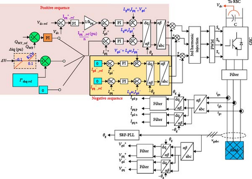
The current is generated through the external reactive power loop when this power is mandated by the grid operator or based on the voltage drop occurring at the PCC as shown in Figure 8 where ΔV represents the voltage drop at PCC. The current is set to zero if the requested reactive power to be injected in to the grid is provided by the STATCOM.

The full control diagram of the grid-side converter is presented in Figure 7.
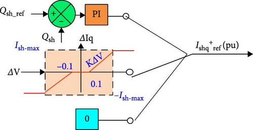
Figure 8 illustrates that if the reactive current required to compensate for the voltage drop is within the maximum current capacity of the STATCOM, the wind farm does not generate any reactive current. In this case, and . The wind turbines will only contribute to the reactive power supply when the required reactive current exceeds the STATCOM’s capacity. In this case, and . In the STATCOM maintenance phases, the reactive power is provided exclusively by the wind turbines. This occurs because the reference reactive current for the STATCOM, , is set to zero, meaning the STATCOM does not contribute to reactive power compensation during this period. Consequently, the wind turbines must supply all the necessary reactive power to the grid.
The control of the reactive power produced by each wind turbine enables the management of the total reactive power supplied by the wind farm to the electricity grid.
5.3. STATCOM Control
The equivalent single-phase diagram of the STATCOM connected to the grid through its filter (Rsh, Lsh) is depicted in Figure 9.
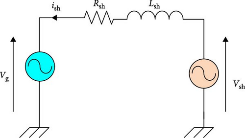
Equation (19) indicates that the active and reactive powers produced or absorbed by the STATCOM are controlled by the direct and quadrature STATCOM currents, respectively. Furthermore, the STATCOM is not intended to supply active power to the grid which means if the negative components of the STATCOM current are canceled by the control algorithm. The STATCOM provides or absorbs a current that is aligned with the q axis and is in quadrature with respect to the grid voltage [29–31] .
The STATCOM can generate reactive power based on a reference set by the grid manager or in response to the voltage drop at the PCC. When all the reactive power is supplied by the DFIG, the STATCOM’s reference reactive current is set to zero. The grid manager has the ability to coordinate the production of reactive energy between STATCOM and DFIG as illustrated in Figure 10.
The STATCOM control design is shown in Figure 11.
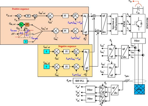
The STATCOM’s reference reactive power must be maintained within the range of −Qsh-max and Qsh−max(−Qsh−max ≤ Qsh−ref ≤ Qsh−max), while the STATCOM’s reference reactive current should remain within the limits of −Ish−max and Ish−max(−Ish−max ≤ Ish−ref ≤ Ish−max). If the required reactive power exceeds Qsh-max, the wind farm will supply the difference, expressed as QWF = Qreq − Qsh−max, which implies that Qsh−max = Qreq − QWF. Since the wind turbines are enable to supply reactive power up to one-third of their active power, Qsh−max is sized accordingly, taking into consideration the amount of reactive power that the wind turbines can contribute. In general, the required reactive power Qreq is proportional to the voltage drop at the connection point of the wind turbines and the STATCOM. Accordingly, the reference reactive current of the STATCOM is set to KΔV(pu), while the reference reactive current of the wind farm is chosen as . The size of the STATCOM, when considering the reactive power contribution from the wind farm, is significantly reduced compared to the size of a STATCOM used alone for the same level of reactive power compensation. This coordinated approach allows the wind farm to share the reactive power burden, optimizing the system’s performance while minimizing the STATCOM’s required capacity, leading to a more cost-effective and efficient solution for voltage regulation and reactive power support during grid disturbances.
The park transformations using θg and −θg angles enable the separation of the positive and negative sequences of the currents supplied by the STATCOM and GSC. Filters are then used to eliminate ripples from these currents achieve smooth quantities. In RSC control, positive and negative sequences are separated using park transformations of θrand − (2θs − θr) angles converting, respectively, from the three-phase (abc) frame to the rotor-related (DQ) frame [32, 33]. During asymmetrical voltage faults, a synchronous reference frame phase looked loop (SRF-PLL) exhibits high performance in tracking the phase of grid voltages [26].
6. Simulation Results
The simulation results are plotted using MATLAB/SIMULINK software, based on the parameters of the wind turbine and STATCOM, as summarized in the Table 1.
| DFIG stator power Ps = 2MW | Phase to phase grid voltage Ug = 690V |
| DFIG rated speed nn = 1500rpm | DFIG rated torque Tn = 12732Nm |
| DFIG rated stator current Is = 1760A | Grid frequency fg = 50Hz |
| Stator resistance Rs = 2.6e−3Ω | Rotor resistance Rr = 2.9e−3Ω |
| Total stator leakage inductance Ls = 2.987e−3H | Total rotor leakage inductance Lr = 2.987e−3H |
| Magnetizing inductor Lm = 2.5e−3H | Maximum DFIG slip gmax = 1/3 |
| Pair of poles p = 2 | Moment of inertia J = 127Kg.m2 |
| Friction coefficient D = 0.001 | DFIG DC voltage Vdc = 1150V |
| Sampling period Ts = 5µs | DFIG DC bus capacitance C = 0.08F |
| Grid side filter’s resistance Rg = 2e−5Ω | Grid side filter’s inductance Lg = 4e−4H |
| Crowbar resistor Rcrowbar = 0.5Ω | STATCOM filter’s inductance Lsh = 4e−4H |
| STATCOM filter’s resistance Rsh = 2e−5Ω | STATCOM DC voltage Vdc-sh = 1150V |
| STATCOM DC bus capacitance Csh = 0.08F | Grid current integral regulator Ki−Ig = 710 |
| Rotor current integral regulator Ki−Ir = 2.04e5 | Grid current proportional regulator Kp−Ig = 37.14 |
| Rotor current proportional regulator Kp−Ir = 284.7 | DC bus integral regulator Ki−Vdc = −60, 000 |
| DC bus proportional regulator Kp−Vdc = −1000 | STATCOM DC bus integral regulator Ki−Vdc_sh = 50 |
| STATCOM current regulator Ki−Ish = 1, Kp−Ish = 250 | STATCOM DC bus proportional regulator Kp−Vdc_sh = 0.5 |
| STATCOM-rated reactive power Qsh = ±36MVar. |
The wind farm, installed in 2009 at Sidi Daoued Elhawaria, has a nominal capacity of 55 MW and can generate up to one-third of its rated capacity as reactive power to comply with the Tunisian grid code. This paper proposes a 36 MVar STATCOM to support the reactive power of the wind turbines and meet the reactive energy requirements of the Tunisian electricity grid.
The power coefficient and the stator power delivered by the wind turbine are illustrated in Figure 12.
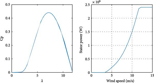
Simulation results are plotted for both symmetric and asymmetric grid voltage, faults as well as in situations where the reactive current is generated by both the DFIG and STATCOM.
6.1. Symmetrical Grid Voltage Faults
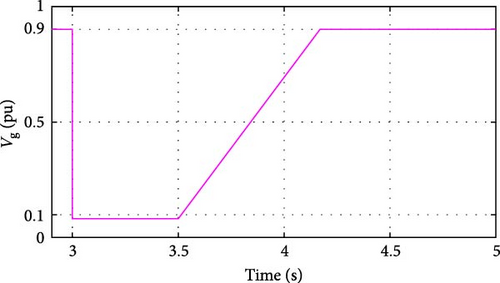
To closely match the LVRT characteristic represented by Figure 2 as required by the Tunisian grid code, the grid voltage profile is shown in Figure 13. A voltage sag with a depth of 0.9 pu and of duration 500 ms occurs at the PCC at t = 3 s, followed by a recovery its nominal value at t = 4.17 s.
In situations where the requested reactive power exceeds the capabilities of both the DFIG and STATCOM, these components must provide the necessary reactive current. However, the supplied reactive power must not exceed a specified limit to maintain the power factor at the PCC as indicated in Figure 4. Figure 14 illustrates STATCOM currents and voltages.
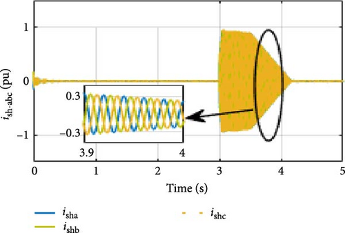
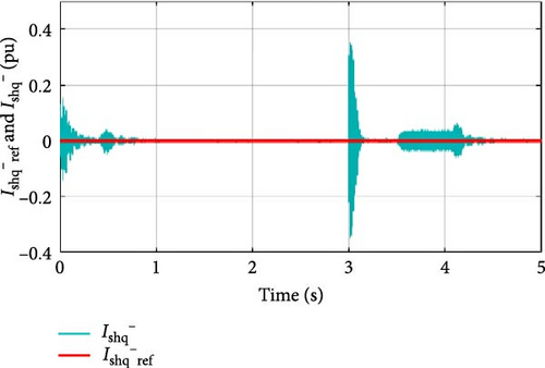
When the voltage drops at the PCC, the STACOM injects a reactive current to compensate for this reduction. The magnitude of this current depends on the severity of the voltage dip. Subsequently, the DFIGs respond by supplying the remaining reactive power. Figure 15 illustrates the electrical quantities for each DFIG during a significant voltage fault.
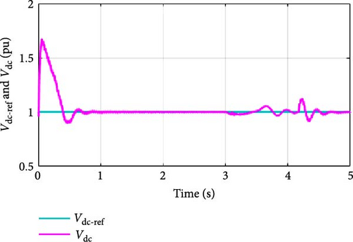
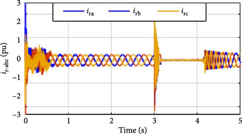
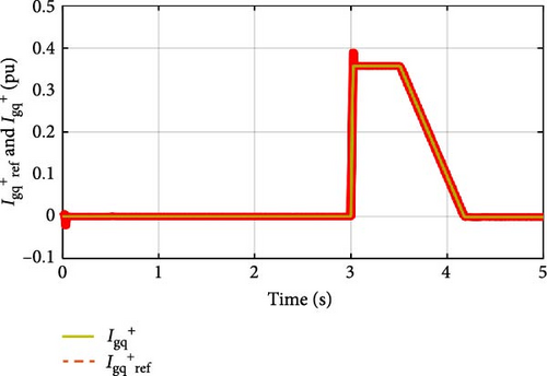
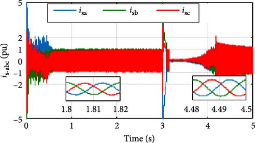
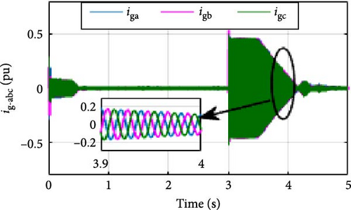
Figures 14 and 15 demonstrate that both the GSC and the STATCOM simultaneously generate the required reactive current while maintaining a stable DC bus voltage at its reference value. Current peaks are effectively mitigated, and their amplitudes remain below the nominal values.
The negative components of the currents and voltages of the DFIGs are zero during symmetrical network faults. Figure 16 illustrates the electrical and magnetic quantities of the DFIG.
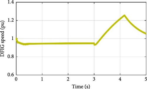
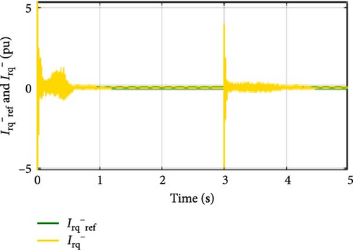
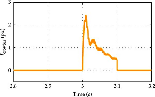
During a significant symmetrical fault in the electrical grid voltage, wind turbines provide the necessary reactive power without producing active power by developing zero electromagnetic torque (Figure 16b). During a voltage fault, the wind turbine speed rises rapidly (Figure 16a), consequently the speed control loop will be activated to ensure that the DFIG speed remains within acceptable limits. To protect the DFIG rotor, the DC bus, and the RSC, a crowbar is activated during the voltage drop. This mechanism dissipates the kinetic energy resulting from the increase in speed and prevents the DC bus voltage from rising, ensuring it remains equal to its reference value. The rotor circuit must be disconnected during the grid voltage fault, which accounts for the zero values of the rotor and stator currents, as well as the electromagnetic torque. The transformation from the (abc) to (dq) frame of the DFIG currents and voltages simplifies the synthesis of the currents and voltages regulation loops, enabling effective control of all wind turbines. Figure 17 illustrates the current flowing through the crowbar.
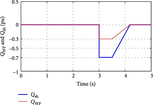
The reactive powers supplied by the STATCOM and the wind farm during a symmetrical voltage fault are depicted in Figure 18.
6.2. Asymmetrical Grid Voltage Faults
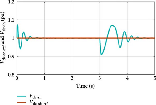
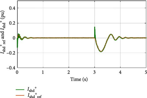
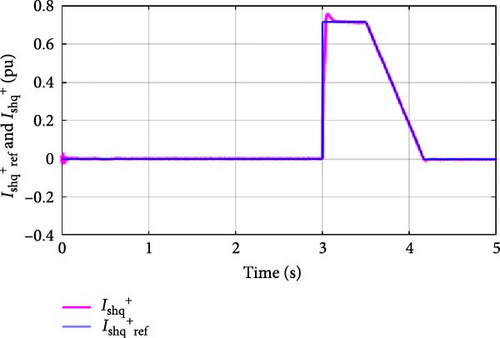
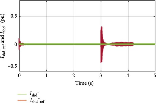
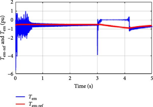
To test the control strategies illustrated in Figures 6, 7, and 11, an asymmetric voltage fault was introduced in the grid during the time interval [3s, 4.2s]. During this fault, the voltage vgb dropped by 0.2 pu and vgc decreased by 0.3 pu, while the voltage vga remained at its nominal value as shown in Figure 19.
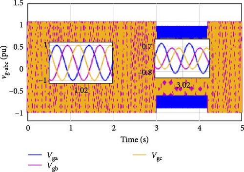
Figure 20 illustrates the evolution of the speed, torque, currents, and voltages of the DFIG in the case of an asymmetric voltage.

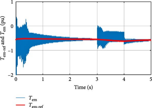
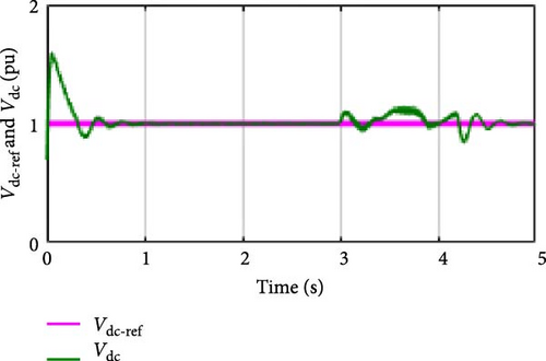
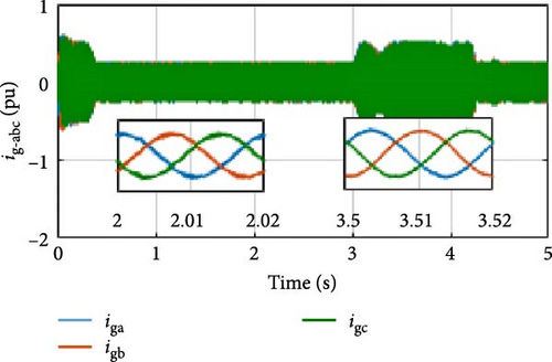
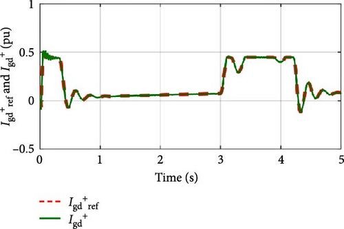
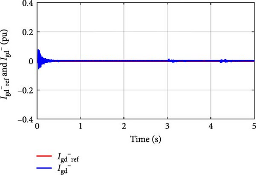

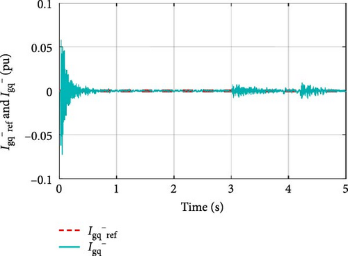
The speed of the DFIG increases when an asymmetrical fault occurs in the power grid, as shown in Figure 20a. During the fault, the electromagnetic torque developed by the DFIG remains below its rated value (Figure 20b). Despite the imbalance in the three phases network voltages, the currents injected by the DFIG during the fault maintain a perfectly sinusoidal shape (Figure 20d).
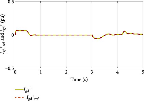
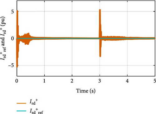
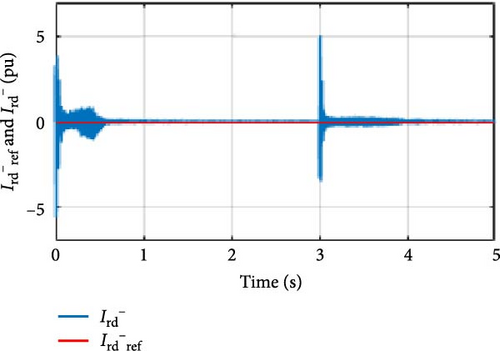
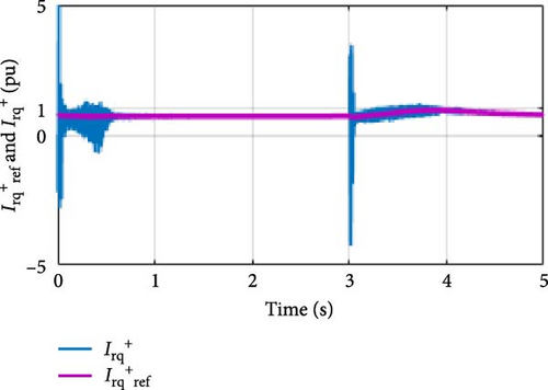
Similarly, the stator and rotor currents maintain a sinusoidal and balanced waveform during the fault as shown in Figure 21. The attenuation of current oscillations during the fault demonstrates the effectiveness and validity of the control method.
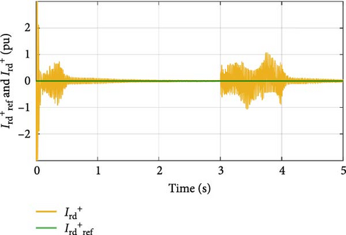
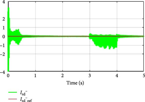
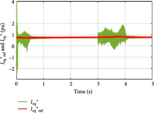

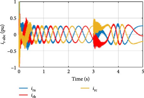
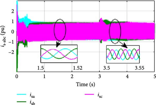
Based on Figures 20 and 21, it can be observed that the stator, rotor, and grid currents maintain a sinusoidal form, with their values remaining below the rated values. Additionally, the DFIG generates a torque lower than the nominal torque, even though its speed increases during the fault. We can also observe that the negative sequence currents remain at zero by following their reference values. Decomposing the control strategy into positive and negative sequences enables the cancellation of the voltage reverse system caused by grid voltage imbalances. In the event of an asymmetrical fault, the STATCOM reacts by injecting reactive current into the network (Figure 22a). The decomposition of STATCOM voltages and currents into positive and negative sequences ensures a sinusoidal and balanced current’s waveform (Figure 22b). The control loops provide precise regulation of STATCOM currents and voltages, allowing the STATCOM currents to closely follow their reference values as shown in Figure 22.
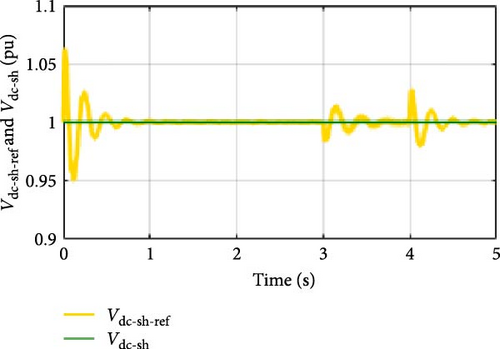
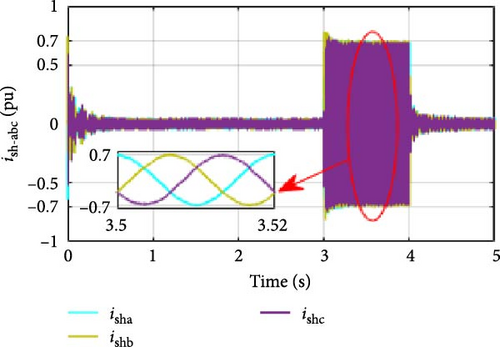
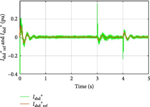
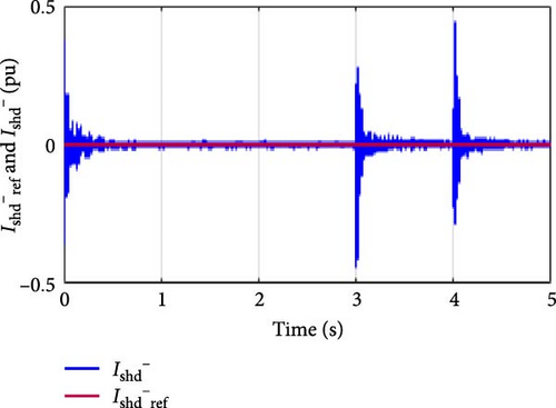
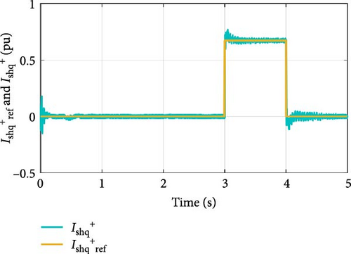
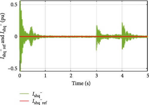
Figure 23 shows the reactive powers generated by the STATCOM and the wind farm during an asymmetric grid voltage fault.
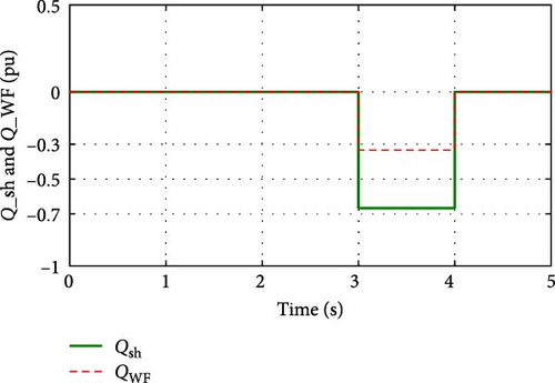
During a symmetrical or asymmetrical fault in the grid voltages, the STATCOM generates all the reactive power needed to correct the fault. If this power exceeds the STATCOM’s capacity, the wind farm provides the additional power required.
7. Conclusion
This paper aims to improve the management of reactive power between a wind farm-STATCOM system and the electrical network during a grid voltage fault. The behaviors of the STATCOM and DFIG-based wind turbines during symmetrical and asymmetrical grid voltage fault are analyzed using Matlab Simulink. The results obtained demonstrate the effectiveness and accuracy of the converter control algorithms. The decomposition of the control algorithms into positive and negative sequences enables wind turbines and the STATCOM to provide perfectly sinusoidal and balanced currents even in the presence of unbalanced grid voltages and during severe voltage dips. The control algorithms are developed to coordinate the generation of the required reactive energy, enabling the cancellation of electrical grid faults between the wind farm and the STATCOM. The STATCOM is prioritized if it can supply sufficient reactive power. If the requested reactive power exceeds the STATCOM’s maximum capacity, the proposed control methods allow the wind farm to provide the remaining required reactive power. One of the advantages of the proposed control method is that the grid operator can select the appropriate reactive energy source by activating either, the STATCOM, the wind turbines, or both simultaneously to generate the requested reactive power, particularly during maintenance periods.
- •
Maximize the extraction of wind kinetic energy by applying the MPPT strategy, in combination with the VOC control method, to the RSC, GSC, and STATCOM.
- •
Generate optimal reference values for rotor, stator, and STATCOM currents to efficiently manage the reactive power exchange between the wind farm, STATCOM, and the electrical grid, ensuring the grid voltage is regulated to its nominal value.
- •
Ensure stable operation of the wind farm, STATCOM, and electrical grid during severe symmetrical and asymmetrical voltage faults by decomposing voltages and currents into positive and negative sequences and mitigating the effects of the negative sequence.
This work can be evaluated in real time by integrating an active energy management algorithm with the proposed reactive energy management strategy. This combined approach aims to control the frequency and voltage of the electrical grid, ensuring the quality of electrical energy and the operational stability of the wind farm, STATCOM, and electrical grid.
The validity and safety of the proposed algorithms are tested using MATLAB-SIMULINK and can be further validated through practical results.
Nomenclature
-
- :
-
- Grid voltage
-
- :
-
- STATCOM voltage
-
- Vdc (V):
-
- DFIG DC voltage
-
- Vdc-sh (V):
-
- STATCOM DC voltage
-
- :
-
- Stator voltage
-
- :
-
- Rotor voltage
-
- p:
-
- Pair of poles
-
- ωm−ref (rd/s):
-
- DFIG reference speed
-
- Lg (H), Rg (Ω):
-
- GSC filter inductance and resistance
-
- Vdc−sh−ref (V):
-
- STATCOM reference DC voltage
-
- f (Hz):
-
- Grid frequency
-
- Csh (F):
-
- STATCOM capacitor
-
- C (F):
-
- DFIG capacitor
-
- ωm (rd/s):
-
- DFIG speed
-
- :
-
- Stator currents (A)
-
- :
-
- Rotor currents (A)
-
- :
-
- Grid currents (A)
-
- :
-
- STATCOM currents (A)
-
- Lf (H), Rf (Ω):
-
- STATCOM filter inductance and resistance
-
- Rs (Ω), Ls (H):
-
- Stator resistance and inductance
-
- Vdc−ref (V):
-
- DFIG reference DC voltage
-
- Qs (Var), Ps (W):
-
- Stator reactive and active powers
-
- Qsh (Var), Psh (W):
-
- STATCOM reactive and active powers
-
- Qg (Var), Pg (W):
-
- Grid reactive and active powers
-
- Qr (Var), Pr (W):
-
- Rotor reactive and active powers
-
- Rr (Ω),Lr (H):
-
- Rotor resistance and inductance.
Conflicts of Interest
The authors declare no conflicts of interest.
Funding
The authors extend their appreciation to the Deanship of Scientific Research at King Khalid University for funding this work through Large Groups (grant number RGP. 2/307/45).
Acknowledgments
The authors extend their appreciation to the Deanship of Scientific Research at King Khalid University for funding this work through Large Groups (grant number RGP. 2/307/45).
Open Research
Data Availability Statement
The data that support the findings of this study are available from the corresponding author upon request.


