Combined Crank-Slider and Rack-Gear Structures for Energy Harvesting and Impact Reduction of the Car Door
Abstract
Harvesting energy from the door closing process provides a promising solution for powering wireless sensors in intelligent transport systems, however issues, such as low conversion efficiency and operational resistance hinder its practical application. In this study, an energy harvesting system (EHS) is proposed and its basic and optimized designs are compared and analyzed. The system integrates a crank-slider mechanism, a rack-and-pinion transmission and a flywheel energy storage module: the crank-slider converts the rotational motion of the door into linear motion, the rack-and-pinion gears are engaged only at preset positions to minimize operating resistance, and the flywheel captures the kinetic energy quickly during the door closing process. The key parameters (crank length: 19.8–25.8 cm; connecting rod length: 25–31 cm; engagement angle: 26°–44°; flywheel inertia: 0–102.6 kg-mm2) were optimized through orthogonal experiments. The results show that the flexible design improves the energy output by 13% compared with the rigid design (35.96–73.79 mJ/time for 1–6 J input), and the orthogonal analysis shows that the eigenvalues of the parameters are distributed in a balanced way, which verifies the feasibility of eliminating the impact kinetic energy loss through elastic contact. In addition, the flexible design reduces the door closing noise by 3–12 dB. Experimental validation shows that the system is capable of providing minute-level continuous power supply for low-power sensors.
1. Introduction
Harvesting environmental energy provides more possibilities for the development of industries and daily life [1–3]. The transportation sector, which is abundant in motion and less constrained by the environment, has attracted the attention of researchers in the field of micro energy harvesting. Various methods have been proposed to generate power by extracting energy from impacts and vibrations [4]. These devices for energy harvesting have opened up a new way to construct the Internet of Things (IoT) by combining energy harvesting techniques with sensor nodes, avoiding frequent battery replacements. Harvesters with different energy conversion mechanisms have been developed, including triboelectric [5], piezoelectric [6], electrostatic [7], and electromagnetic [8] generators. Matching the features of generators with different environmental conditions is crucial for ensuring high output power [9, 10]. The up frequency conversion approach is therefore promoted for low-frequency kinetic energy sources, for instance, in the case of walking, vehicles passing overspeed bumps or tidal energy [11–13]. Yang et al. [14] introduced a device for capturing tidal energy using a gear amplification mechanism to convert low-frequency vibrations into high frequency vibrations on a piezoelectric device. Luo et al. [15] developed a device for energy recovery from human walking by converting linear motion into high-speed rotational motion and using electromagnetic induction for energy conversion.
In the transportation sector, vehicles with frequent vibration excitation, which can be utilized for energy harvesting, are worth exploring further [16, 17]. Based on the scenarios, the transportation energy harvesters can be categorized into road harvesters [18, 19], track harvesters, [20–22] and vehicle harvesters [23]. Song et al. [24] designed a device that captures the energy generated when cars pass overspeed bumps by compressing nonconductive metal rods and piezoelectric materials in series. Qi et al. [25] developed a device that converts low-frequency vibrations from speed bumps into high frequency vibrations using a gear amplification mechanism and transmits this energy to a generator for harvesting. Zhang et al. [26] created a device that uses the deformation caused by cars passing overspeed bumps as hydraulic pressure to drive an electric motor for energy collection. Zuo et al. [27] designed a device installed on sleepers that utilizes the vertical deformation of tracks and sleepers caused by vehicle movement to convert vibration energy. Hou et al. [28] proposed the electromagnetic vibration energy harvesters (EM-VEHs) set adjacent to the track slab to supply enough power for sensors.
Apart from the traditional road-mounted and track mounted harvesters, researchers are currently showing significant interest in exploring the potential of harvesting wasted energy in vehicles. The available energy sources include excessive forces applied by drivers to brake pedals, steering wheels, and doors under stressful conditions, thermal energy from engine exhaust [29], shock energy absorbed by suspensions from uneven road surfaces [30, 31], and braking energy when vehicles decelerate [32–34]. Qi et al. [35] designed an electromagnetic brake energy harvesting device that uses a helical spring to recover braking energy. During the braking process, the helical spring captures kinetic energy produced by the engine which is then used to power an electric motor for electricity generation. Goldner et al. [36] developed a linear suspension energy harvester that captures kinetic energy using an electromagnetic linear generator. Xu and Guo [37] designed a hydraulic suspension vibration energy harvesting device to capture the impact energy from the ground on the vehicle. Suda and Shiiba [38] used a mechanical approach to convert low-frequency vibrations into high frequency vibrations for electromechanical conversion using a gear and rack system with a generator. Qian et al. [39] created a hybrid device with both electromagnetic and triboelectric transducers to collect electrical power generated by the rotation of vehicle wheels for tire pressure sensors. Nanogenerators have been widely used in automotive energy harvesting as self-powered sensors [40, 41]. Xie et al. [42] studied the kinetic energy of brake pedals and designed a scissor-type energy harvester to collect excessive forces applied by drivers to the brake pedal. When the driver presses the brake pedal, the gear and rack system is driven by the external force on the push rod, which in turn rotates the flywheel at high speed to convert the kinetic energy into electrical power. Liu et al. [43] studied the extraction of energy from vehicle exhaust and designed corresponding energy harvesters.
Until now, the majority of energy harvesting studies in the automotive industry have been centered around the development of braking and suspension systems. Besides, relatively less attention has been given to the potential for extracting kinetic energy from car wheels, steering wheels, and brake pedals. However, doors in vehicles that are frequently used with abundant kinetic energy have been overlooked in terms of their potential for energy harvesting. In addition, there has been research conducted on the energy-collecting process from the motion of doors in buildings [44]. There are also studies of its applications and potential, from which the analysis results show bright prospects for development in this direction [45, 46]. Litwhiler and Gavigan [47] proposed a device to harvest kinetic energy generated during the process of opening and closing doors. When the door opens, the output shaft of the electric motor fixed at the other end of the rod rotates to generate electricity. Litwhiler and Gavigan [48] conducted similar research and developed a smaller harvester by using a compact and precise short rod instead of a long rod. However, due to the relatively low rotational speed and the lack of up frequency conversion mechanism and mechanical energy storage element, the electromechanical energy conversion efficiency is not very high [49, 50]. Luo [51] designed an energy harvester that recovers kinetic energy from door opening and closing, which uses a fixed axis pulley system to amplify the door’s angular velocity and store kinetic energy with a flywheel. This device boasts an ingenious structure, impressive output power and remarkable mechanical efficiency, but it requires a continuous application of 120N force to drive the device during laboratory testing. Notably, most present devices for door kinetic energy harvesting suffer from (1) the overburden effects during the door’s normal operation due to the direct connection structure which imposes too much resistance; (2) the low energy conversion efficiency due to the lack of mechanical energy storage elements and frequency-up machine to capture the kinetic energy of the door as possible. Therefore, there is significant research potential in developing a door-closing kinetic energy harvester that can extract kinetic energy from doors without affecting their operation and simultaneously achieve high electromechanical conversion efficiency.
This paper proposes a novel structure for capturing the kinetic energy of car doors without compromising their functionality. The following innovative features are presented: First, a delayed combination of the rack-gear structure is developed to avoid overburdening passengers. Second, a flywheel energy storage system and a two-stage amplification mechanism are employed to capture energy efficiently during the rapid closure of the doors for electromechanical conversion. Third, a low-power generator and a gearbox with a high transmission ratio are utilized at the hinge to calculate the angular velocity and slightly improve energy harvesting efficiency. Fourth, the energy harvester incorporates elastic elements to enhance mechanical efficiency, and the design’s rationality is substantiated by simulation and empirical results from device testing. Fifth, the practicality of the design is validated through a real-world application test of the energy harvester in conjunction with a low-power sensor.
2. Design
Figure 1 shows the EHS (energy harvesting system) which is designed to scavenge kinetic energy from the door-closing motions, featuring the ability to provide efficient energy output without obvious burden effects. As seen in Figure 1a, b, the device installed between the door and the vehicle body consists of three main components: a two-stage amplification structure, a flywheel energy storage system, and a generator. The yellow mass is used as the representation of the door mass. The conversion of kinetic energy is depicted in Figure 1c, where two branches of energy flow are visible. The first branch is from the crank-slider structure, which passes through the gearbox before reaching the flywheel and generator, while the second branch is directly converted by the hinged generator.
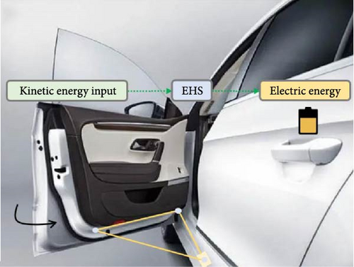

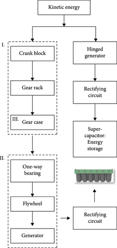
During the rigid design phase, flywheel energy storage systems exhibited insufficient startup performance under low kinetic energy conditions. To address this, an alternating current (AC) generator was integrated at the hinge, directly converting door motion energy through mechanical coupling, significantly improving energy harvesting efficiency in low kinetic energy scenarios. After transitioning to a flexible design, the addition of elastic buffer elements further enhanced the dynamic response of the flywheel system. Although the hinge generator’s energy contribution ratio decreased, its role as a functional supplement remained critical. The system adopts a flywheel direct current (DC) generator as the main energy harvesting unit, while using an articulated AC generator to achieve auxiliary energy conversion, forming an efficient EHS.
As shown in Figure 2a–d, the low-speed rotational motion of the door is converted into linear motion of the slider via a crank-slider mechanism, then transmitted through a rack-and-pinion system and gearbox to drive the flywheel at high speed. To avoid the additional heavy feeling during the door-closing operation, the slider is not engaged in the rack-gear mechanism until it reaches a preset position. This preset position can be adjusted by the assembly of the rack. As shown in Figure 2e, the flywheel system consists of a gearbox, a ratchet-type one-way bearing, a flywheel assembly, and a DC generator. The gearbox converts the linear motion of the slider into high-speed rotation of the flywheel, while the flywheel assembly serves as a kinetic energy storage unit, where the stored energy is converted into electricity via the DC generator. The ratchet-type one-way bearing ensures independent rotation of the flywheel assembly during input kinetic energy decay. To prevent additional resistance during door opening with the energy harvester and eliminate noise caused by ratchet engagement in no limit directions, an industrial-grade one-way bearing is implemented on the gearbox input shaft.
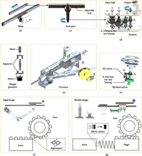
Notably, two possible designs are developed for the engagement between the slider and the rack-gear mechanism. In the rigid design in Figure 2f, the slider also works as the rack in the rack-gear mechanism in which the slider (rack) contacts the input gear of the gearbox in a pattern of rigid impact. Alternatively, a flexible design is proposed in Figure 2g. The rack fixed on a separate stationary slider is already engaged with the gearbox. As the primary slider in the crank-slider mechanism moves close to a preset position of the secondary slider, the two sliders will interact through a spring. As a result, the rack will be driven in an elastic contact way to avoid rigid impact. When the door is opened, the stationary slider will be restored to its original position by utilization of magnetic attractive force or a returning link between the two sliders. To find the optimal solution, the two designs are both considered and compared in the following sections.
3. Modeling
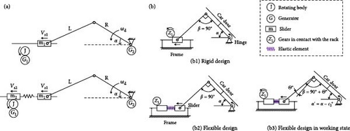
Both rigid and flexible designs can be generally approximated with the model in Figure 3a. Here, L represents the length of the connecting rod, R is the length of the crank, is the input angular velocity of the crank assembly and αc is the angle between the crank and the body (in particular, with αc = αas the preset impact position where the rack is engaged with the gear), Vs1 and Vs2 are the linear velocities of the primary and secondary sliders, ms1 and ms2 are the masses of the primary and secondary slider assemblies, RL1 and RL2are motor loads, and J is the moment of inertia of the flywheel.
Einc is the kinetic energy of the crank-slider mechanism, Efw is the kinetic energy of the flywheel energy storage device, EGb is the kinetic energy of the gearbox, Eh_g is the energy consumed by the hinge motor, Ef1 is the energy consumed by the slider, and Eip is the impact loss energy.
Here, Jsh1fw is the equivalent rotational inertia of the flywheel energy storage and generator device at the input shaft, ω1 = VS1/r1 is the angular velocity of the input shaft and r1 is the pitch circle radius of gear Z1 on axis 1, Fffw is the equivalent friction force on the output shaft, rf is the radius of the bearing roller track on the flywheel holder, ωfw = i72ω1 is the flywheel speed and i72 for the overall gear ratio between the output shaft and the input shaft, i98 is the gear ratio of the flywheel device gear system, Cfw is the damping of the flywheel system, βfw is the electromechanical coupling coefficient from the generator, and Rfw is the internal resistance of the flywheel system generator.
Here, Efwc is the total energy of the flywheel system when it operates independently and Jfw is the moment of inertia of the flywheel system.
Here, Ffs1 is the friction force of the slider.
Among them, e is the coefficient of restitution (the steel-on-steel coefficient of restitution is 0.56). Both the parameter e and Equation (12) are referenced from the collision theory section of Theoretical Mechanics II [52].
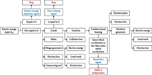
With the energy model developed for both rigid and flexible designs in Equations (6) and (15), the dynamics can be derived by differentiating the energy related to time. Therefore, the corresponding simulation model can be established. For easy understanding, the energy flow of the proposed door harvester is illustrated in Figure 4.
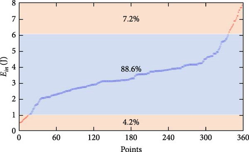
In general, different drivers or passengers apply varying amounts of kinetic energy to close the door. To ensure that the performance analysis of the energy harvester is more practical, extensive tests have been conducted by recording the random door-closing actions on the test bench and the results have been statistically analyzed in Figure 5. The kinetic energy applied to the crank of the energy harvester is mainly distributed between 1 and 6 J with the probability of about 88.6%. The door is not likely to be closed with an input energy of less than 1 J while it is too noisy and easily damaged with input energy over 6 J. Therefore, the input energy of the energy harvester is restricted between 1 to 6 J for performance analysis.
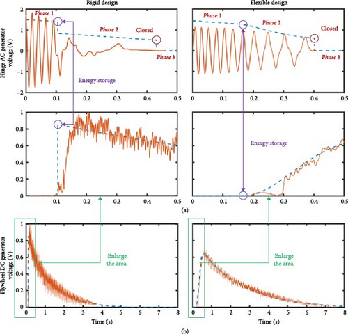
To verify the proposed model, Figure 6 shows the simulated results and the experimental results for the two different designs, rigid and flexible, with different input energy. Notably, the experimental voltage waveforms of the AC hinge generator are plotted against the simulated voltage envelope and both simulated and experimental voltage of the DC flywheel generator are plotted in the same picture. Several different stages are observed: in phase 1, the door begins the closing process with an initial velocity and drives the crank-slider mechanism with the AC hinge generator producing electricity; in phase 2, the rack-gear structure works after the impact between the sliders and gears and drive the flywheel with the DC generator; phase 3, the door is closed while the flywheel continues rotating to drive the DC generator. A good match between simulations and experiments validates the effectiveness of the proposed models for two different designs. However, some differences can be observed between the two designs. A sudden voltage drop of the AC hinge generator happens at the impact moments for the rigid design while the flexible design shows a smoothly declining trend. Moreover, the flexible design shows a much longer energy conversion duration than the rigid design.
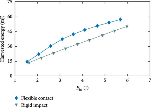
In order to systematically verify the applicability of the kinetic model under typical working conditions, Figure 7 demonstrates the results of the simulation and analysis based on the parameter combinations of crank length R = 21.8 cm, connecting rod length L = 27 cm, crank angle α = 26° and no additional load configuration (nfw = 0). It is shown that the flexible collector exhibits superior energy conversion characteristics within the calibrated kinetic energy input interval, and its output efficiency has a significant improvement over the rigid structure.
To ensure an effective mapping between the Simulink dynamics model and the actual test rig, a hierarchical calibration strategy is adopted for the model parameters: the measured data from the test rig are given priority, and for the parameters that cannot be measured directly, the values are assigned with strict reference to the technical specifications provided by the equipment manufacturer. The main physical parameters involved in the model and their calibration basis are shown in Table 1. Although the industrial grade ball linear slide with grease and mechanical lubricant has been adopted as the multistage lubrication scheme, and the impact energy loss of the rigid collector has been optimized by the structural topology, the friction of the slide is still the key bottleneck that restricts the improvement of the energy recovery efficiency, and it is the optimization direction that needs to be focused on.
| Symbols | Value | Symbols | Value |
|---|---|---|---|
| ms1 | 0.75318 kg | r1 | 15 mm |
| ms2 | 1.89373 kg | 0.0306 V/rad | |
| Jcr | 0.8902⋅106 kg · mm2 | Ch_g | 0.0001 (N · m)/rad |
| Jsh1fw | (3960 + nfw⋅3418) kg · mm2 | Rh_gAC | 420 Ω |
| Fffw | 0.00825 N | Ffs1 | 2 N |
| rf | 20 mm | e | 0.56 |
| Cfw | 0.00003 (N · m)/rad | Ffs2 | 2 N |
| βfw | 0.0124 V/rad | K | 1.246 N/mm |
| Rfw | 34.2 Ω | i72 | 10 |
| Jfw | (39.6 + n⋅34.18) kg · mm2 | i98 | 1.454 |
| Jsh1Gb | 956 kg · mm2 | ih_g | 16.67 |
| FfGb | 0.5 N | CfGb | 0.0001 (N · m)/rad |
The improvement in performance due to the flexible contact structure can be attributed to two factors: (1) Elastic elements effectively reduce energy losses caused by rigid impact; (2) During the compression of the elastic elements by the active slider, the angle between the connecting rod and crankshaft is reduced, resulting in a decrease in the perpendicular force on the crankshaft by the connecting rod. This allows for better door closure and energy conversion. As shown in Figure 3b, an extreme scenario corresponds to the dead angle of β = 90° where the large impact force between the gear and rack in the rigid design is perpendicular to the crankshaft. After a rigid impact contact between the gear and rack, the crankshaft’s rotational speed decreases sharply, and it stops rotating after moving a certain distance. However, at this point, the crankshaft has not yet aligned with the vehicle body and the door is stuck. While this situation can be managed through structural design to ensure proper door closure, it reduces the energy production of the hinge motor, leading to a decrease in the overall energy conversion efficiency (η). However, the same situation can be relieved by the elastic deformation of the spring which means smaller retardation force and smooth transition of the dead angle. The deformation of elastic components helps maintain the door’s speed, making it easier for the door to close. Under the same horizontal configuration and kinetic energy input conditions, the flexible contact approach resolves issues related to impact losses in rigid structures and structural interactions that result in shorter crankshaft travel. This further increases the amount of energy converted by the hinge motor and enhances the overall energy recovery efficiency of the device. In addition, the impact of the door at the closing moment can be significantly reduced with improved comfortability, since a considerable part of kinetic energy has been converted to electricity or dissipated by the proposed harvested.
4. Results
4.1. Experimental Setup
The installation environment of the test bench and the connection of its test equipment are shown in Figure 8. This study minimized environmental impacts on rigid-flex design analysis through systematic environmental control, equipment calibration, and standardized protocols. All experiments were conducted in a controlled laboratory (25 ± 2°C, 80 ± 5% RH) with fixed equipment parameters. The test setup was secured on a 98 cm × 98 cm × 0.8 cm glass substrate using adhesive tapes and foam blocks for mechanical stability. Pretrial system checks included fastener torque verification, drive component lubrication, and electronic contact inspection to maintain consistency with data acquisition systems.
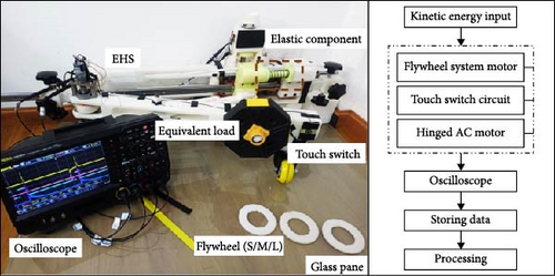
In order to systematically investigate the performance characteristics of rigid and flexible design solutions, this study adopts the orthogonal test analysis method to construct an experimental scheme, aiming to achieve a dual objective: firstly, to comprehensively investigate the influence mechanism of multifactorial coupling on the output of the system, and secondly, to control the experimental scale within engineering feasibility through scientific design. More importantly, the method is able to systematically analyze the effects of each design parameter by means of mathematical tools, such as polar deviation calculation, which provides a quantitative basis for parameter optimization.
This experiment established an orthogonal test system based on four key parameters: crank radius (R), connecting rod length (L), preset angle (α), and flywheel inertia adjustment parameter(nfw). Each parameter was set with four optimization levels: R at 19.8, 21.8, 23.8, and 25.8 cm; L at 25, 27, 29, and 31 cm; α at 26°, 32°, 38°, and 44°; nfw (number of flywheel discs) at 0, 1, 2, and 3. Following the L16 (44) orthogonal array, 16 experimental groups were designed (parameter combinations shown in Table 2), achieving full combinatorial coverage of the four-factor four-level system.
| Combination | Factors | |||
|---|---|---|---|---|
| Crank R (cm) | Connecting rod L (cm) | Angle α (°) | nfw (flywheel inertia [kg.mm2]) | |
| 1 | 19.8 | 25 | 26 | nfw = 0 (0) |
| 2 | 23.8 | 29 | 26 | nfw = 2 (68.4) |
| 3 | 25.8 | 31 | 26 | nfw = 3 (102.6) |
| 4 | 21.8 | 27 | 26 | nfw = 1 (34.2) |
| 5 | 21.8 | 31 | 38 | nfw = 0 (0) |
| 6 | 25.8 | 29 | 32 | nfw = 0 (0) |
| 7 | 23.8 | 27 | 44 | nfw = 0 (0) |
| 8 | 19.8 | 31 | 44 | nfw = 2 (68.4) |
| 9 | 25.8 | 25 | 44 | nfw = 1 (34.2) |
| 10 | 19.8 | 29 | 38 | nfw = 3 (102.6) |
| 11 | 21.8 | 29 | 44 | nfw = 1 (34.2) |
| 12 | 21.8 | 25 | 32 | nfw = 2 (68.4) |
| 13 | 23.8 | 25 | 38 | nfw = 3 (102.6) |
| 14 | 23.8 | 31 | 32 | nfw = 1 (34.2) |
| 15 | 25.8 | 27 | 38 | nfw = 2 (68.4) |
| 16 | 19.8 | 27 | 32 | nfw = 3 (102.6) |
Data analysis focused on two core metrics: (a) the average efficiency values corresponding to different parameter levels and (b) the range values of each factor. Through range analysis methodology, the maximum efficiency variation range between parameter levels was calculated to quantitatively evaluate their regulatory intensity on system performance–larger range values indicate higher sensitivity of the parameter to efficiency changes. Simultaneously, statistical analysis of average efficiency values at each parameter level enabled intuitive identification of optimal parameter trends, providing critical decision support for design optimization.
4.2. Performance Analysis
The experimental protocol employed an L16(44) orthogonal design with 16 parameter sets, testing both rigid and flexible collector structures (32 total experimental groups). Multiple randomized trials generated dynamic data across 1–6 J kinetic energy inputs, filtered based on energy distribution. Additional trials supplemented underrepresented parameter sets. The analysis utilized 190 valid datasets (760 subdata) for rigid collectors and 132 (528 sub-data) for flexible ones. Each dataset included: (1) DC/AC motor output voltages. (2) trigger signal voltage from the crank-end microswitch. (3) oscilloscope waveform snapshots. Data was stored with “Date-Group ID-Sequence” naming conventions, retaining all records except anomalies caused by switch damping effects.
The results of the rigid design are shown in Figure 9. The red stars represent the harvested energy during a single door-closing event while the blue triangles are the corresponding energy conversion efficiency. To highlight the contrasts, trend lines were obtained by fitting the data points. Noticeable differences exist among various horizontal combinations, with certain combinations exhibiting outstanding output performance while others show relatively poor output. In contrast, the experimental results for the flexible design are also plotted in Figure 10. To make a fair comparison purpose, the average conversion efficiency of different tests in the same combination is used. For the rigid design, the two cases with the top average conversion efficiency are combinations 1 and 16 while the combinations of 11 and 15 show the bottom average conversion efficiency. The conversion efficiency for combinations 1 and 16 remains relatively high, while combinations 11 and 15 exhibit relatively low conversion efficiency as the rigid case. Notably, the relatively low energy conversion efficiency is induced by the high loss of the DC generator in the low torque applications (exactly the case of this paper) due to the intrinsic resistive torque. It is expected that the efficiency can be obviously improved if dedicated designs are developed to reduce the intrinsic damping of the generator as much as possible.
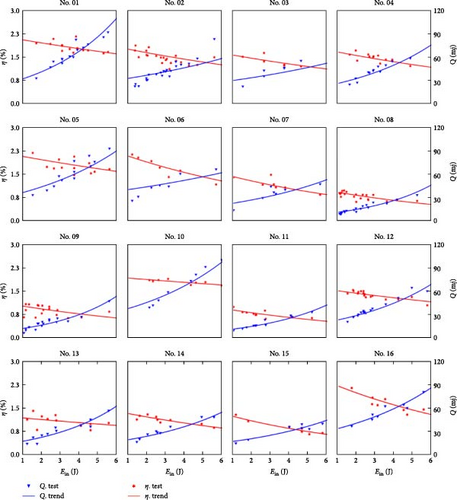
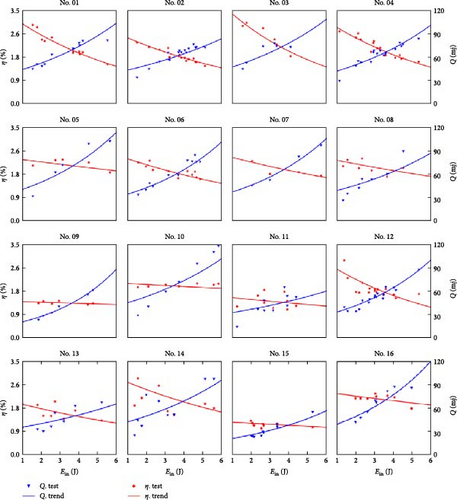
It is easily found that the energy conversion efficiency always decreases with the input energy for both cases, but the declining rate is different. The possible reason is that the impact loss during the contacting process rises obviously with the input energy. However, the harvested energy always increases with the input energy for both cases. In particular, most combinations in the flexible case show obvious improvement in conversion efficiency over those in the rigid case. Furthermore, the declining rate of the energy conversion efficiency gets flatter in the flexible case than in the rigid case, which indicates that the elastic elements effectively reduce the losses generated by impacts, with the effect becoming more pronounced with an increase in kinetic energy input.
The dynamic model indicates that the efficiency and the harvested energy output are closely related to the four selected factors, R, L, α, and nfw, which is also evident in the experimental tests. The impact losses during the operation of the energy harvester depend on the equivalent mass and the velocity of the slider assembly. To clarify the impact of the four parameters on the output, this study employed the method of range analysis to process the experimental results from orthogonal analysis. To ensure the applicability of the range analysis results, the data was normalized by the average value of each factor and the output in each combination with the results shown in Figure 11. The four graphs above show the average values of the four levels regarding efficiency in the orthogonal design, and the last graph shows the results of the range analysis of the four levels regarding efficiency. In order to make the results of the range analysis of the two structures comparable, they are normalized and shown by the percentage of the total occupied. The larger the value of the range, the higher the level’s impact on efficiency.
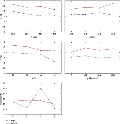
In general, the number of flywheel blades nfw affects the moment of inertia, thereby influencing the equivalent mass. However, the influence is not so obvious. It is observed that the device’s performance is relatively better when equipped with one or three flywheels compared to the cases with zero or two flywheels. This is because changing the rotational inertia of the flywheel has two effects on the rigid structure. The first effect is that when the flywheel is rapidly accelerated to high speed in a short period, it drives the motor to operate at a high speed, increasing the energy output density and total amount but with a shorter working duration. The second effect is that when the flywheel is not accelerated to a high state in a short period, the flywheel system, due to its large moment of inertia, can drive the motor to operate for an extended period, enhancing the total electrical energy output.
With the gear ratio fixed, the changes in the crank, connecting rod, and angle parameters directly affect the transmission of the secondary amplification mechanism related to the Cvw value. Unlike the moment of inertia, the impact of the three parameters (R, L, and α) in the crank-slider mechanism on the Cvw value is nonlinear. According to the partial derivatives of Cvw with respect to R, L, and α separately, it is evident that, under the influence of a single variable, the increase in crank and angle has an inhibitory effect on Cvw, while the increase in connecting rod length amplifies the impact on Cvw. However, this trend is only applicable within a certain range, since the performance reaches the best for L = 29 cm and subsequently decreases. As the energy input increases, a smaller equivalent mass of the colliding body does not necessarily result in lower impact losses and better harvesting efficiency.
The range analysis results for the rigid design indicate that the parameter with the greatest impact on the conversion efficiency η is the crank angle at the contacting position, α. Since an increase in the crank angle α amplifies the impact effects of R and L on Cvw, the crank angle α has the most significant influence on Cvw. On the other hand, in a rigid design, when the crank angle α approaches 45°, the crank-slider mechanism is prone to forming a right-angled triangle at the initial contact of the rack and pinion, resulting in the maximum impact on the crank by the connecting rod and the smallest tangential force on gear 1. As a consequence, starting the flywheel becomes more challenging. Experimental observations support this analysis that the door is difficult to close with α equal to 38° or 44°, leading to relatively low flywheel speed. Flexible contact structures effectively address this issue. The range analysis for the flexible design indicates that, with the help of the elastic spring, the influence of the four factors on the harvested energy becomes flatter. The crank angle α is no longer the primary factor and the structure design requirements can be greatly simplified.
Based on range analysis, the optimized combinations of four factors for the two designs can be determined. For the rigid case, the optimized combination is R = 19.8 cm, L = 29 cm, α = 26° and nfw = 1. For the flexible case, the optimized combination is R = 19.8 cm, L = 31.0 cm, α = 26°, and nfw = 1. The tested results are shown in Figure 12. It is noted that the optimized combination does not belong to the 16 combinations tested, but is derived from the range analysis. The average conversion efficiency is 1.92% for the rigid design and 2.35% for the flexible design. As the input energy is above 5 J, the harvested power is around 100 mJ for the rigid case, and 110 mJ for the flexible case.
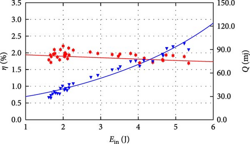
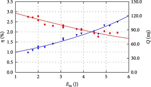
Flexible designs demonstrate significant advantages in low-to-medium energy input scenarios, where the buffering effect of elastic components effectively regulates energy conversion processes. However, when input energy exceeds the energy storage threshold of these elastic elements, system optimization gradually approaches theoretical limits. Orthogonal experimental analyses reveal a declining trend in energy harvester conversion efficiency as input energy increases: in rigid designs, collision energy loss proportional to the square of velocity causes rapid efficiency deterioration, while in flexible designs, energy storage components optimized primarily for low-kinetic output scenarios enhance average performance but exhibit limited optimization efficacy under high energy inputs. Nonetheless, the amplification effect of energy baseline ensures that absolute system output energy maintains proportional growth with input energy.
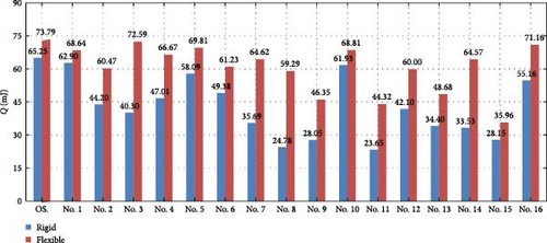
In order to demonstrate the improvement of the optimized design, the normalized average harvested power which is obtained by the product of the average efficiency and the average input power of 3.5 J are plotted with the results of the optimized solutions for both designs as shown in Figure 13. The optimal design has a harvested energy value of 73.79 mJ versus the worst case of 35.96 mJ with the flexible design and 65.25 mJ versus 23.65 mJ correspondingly with the rigid design. Clearly, the flexible design outperforms the rigid one in all combinations and an enhancement of 13.09% is reached by the flexible design over the rigid one for the optimal cases.
4.3. Noise Reduction Performance of the Device
The flexible energy harvester integrates both kinetic energy collection and noise reduction functions. By absorbing redundant kinetic energy input through the electromechanical conversion mechanism and transmission mechanism, it reduces the angular velocity during door closure, thereby achieving noise reduction functionality. As shown in Figure 14, under the same kinetic energy input conditions, compared to the noise emitted by the test stand (retaining only the crank and fuselage) at the moment of crank-fuselage contact, the flexible contact-type energy harvester under optimal parameters reduces noise by 3–12 dB during the crank-body contact moment.
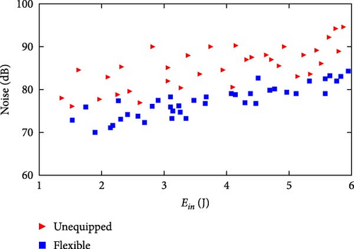
To simulate the final stage of door closing, the noise reduction performance test data in this study specifically refers to the noise generated during crank-body contact. To control single variables, noise from the gearbox operation phase, active/passive slider contact moments, and universal wheel-ground friction during crank rotation was not recorded, as these can be mitigated or eliminated through structural design in engineering applications. Gearbox noise can be reduced by adopting metal matrix composites (such as Al-SiC aluminum composites or magnesium alloys) combined with DLC (diamond-like carbon) coating technology to construct lightweight and noise-reducing gear transmission systems, or through acoustic enclosures, lubrication system upgrades, and transmission stage optimization. Slider contact noise can be diminished by adding polyurethane buffers. The universal wheel-ground contact phase is eliminated in door applications via integrated crank-door design. The gear-rack mechanism of rigid energy harvesters generates significant noise during meshing moments, and due to this inherent defect, they are excluded from noise reduction performance comparisons.
4.4. Application
The energy harvester is adaptable to scenarios with motion patterns similar to vehicle doors, such as electric doors, restroom doors, and heavy-duty vehicle doors, as shown in Figure 15a. While parameter adjustments are required for different applications, its core design and parametric methods ensure cross-environment applicability. For instance, in heavy-duty vehicle doors where the moment of inertia exceeds conventional test bench standards, the system addresses high energy absorption demands by increasing flywheel inertia, enhancing spring stiffness, and proportionally adjusting parameters like crank length R and connecting rod length L. This configuration optimizes stress distribution and slider speed control during kinetic energy transfer, while calibrated generator damping parameters accommodate low-speed closing conditions. By collecting energy through interface circuits, the device continuously powers sensors for temperature, acceleration, altitude, and wind speed, establishing a self-powered sensing system. Such systems, when deployed in enclosed spaces like buildings or vehicles, not only reduce maintenance costs of battery-powered sensors but also provide sustainable solutions for IoT-enabled condition monitoring.
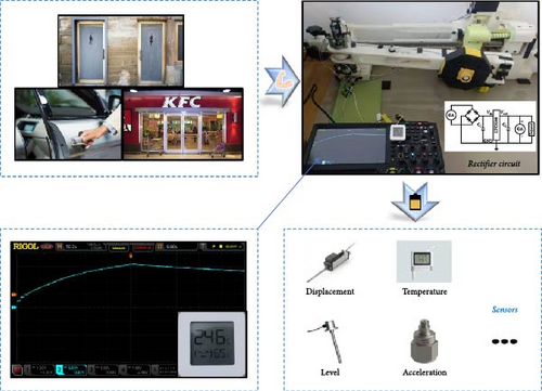

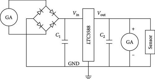
In this study, the feasibility of using a flexible energy harvester to power a low-power temperature/humidity sensor is experimentally verified. Typical shutdown operations are simulated by 32 consecutive kinetic energy input experiments, and the experimental data show that the voltage decay curve of the storage capacitor C2 shows significant agreement with the theoretically predicted trend, and that its single energy harvesting magnitude can support the sensors to achieve a continuous power supply at the minute level. Figure 16 shows the complete structure of the power supply system, including the energy harvester, conversion module, storage capacitor and sensor, while Table 3 details the key component parameters.
| Component | Technical indicators |
|---|---|
| Capacitors for energy storage, C2 (F) | 3.3e–3 |
| Capacitors for filtering, C1 (F) | 4.70e–4 |
| DC–DC conversion module | LTC3588 |
| Sensor type | Humidity sensor |
| Electrical marking GA | Hinge AC generator |
| Electrical marking GD | Flywheel DC generator |
| Diode type | Nitro diodes |
Crank rotation drives the AC motor at the hinge to generate electricity. After AC-DC conversion via a rectifier bridge and filter capacitor C1, the converter module provides target voltage outputs, simultaneously charging the storage capacitor C2 and powering the sensors. When the crank reaches preset positions, the flywheel inertia activates the DC motor to generate power. Constrained by the output characteristics of the motor (limited output voltage amplitude), the energy generated is sent directly to the storage capacitor C2 and the sensors without secondary processing by the converter module. Subsequent optimisations will include power management modules tailored to specific motor output characteristics.
In the specific context of automotive door engineering, collector connecting rods face significant challenges in terms of human–machine interaction. During the boarding and alighting processes, the trajectory of the occupant’s legs may interfere with the connecting device. This interference is particularly evident during the processes of door opening and closing. The connecting rod of the collector has the potential to exert a mechanical impact on the anterior aspect of the occupant’s lower leg. This phenomenon hinders the practical application of the technology. To address this critical issue, this paper innovatively proposes the use of a curved connecting rod instead of a straight structure (Figure 15b). The linkage is constructed in such a way that when the door is closed, the linkage is completely hidden within the space at the bottom of the body, thus ensuring that it does not interfere with the occupant’s movement area. The avoidance of the occupant’s activity area is achieved while maintaining an equivalent linear distance between the two hinges. The validity of the proposed methodology is confirmed by the results of 3D kinematic simulations, which also demonstrate the geometrical compatibility of the curved linkage and that its kinematic parameters are orthogonally equivalent to those of the linear structure. This ensures the effective migration of existing theoretical conclusions.
Notwithstanding the functional equivalence of the proposed curved linkage collector and the flexible contact collector, there are still engineering issues that require further investigation. These include friction dynamics, inertial load distribution, and the optimization of the radius of curvature, as well as the safety of human–machine interaction. To this end, the subsequent research will concentrate on two aspects: firstly, collaboration with mainstream automotive manufacturers to develop real-vehicle adaptive prototypes, thereby enabling systematic assessment of the body integration matching degree, whole-life maintenance cost and long-term operational reliability; secondly, vehicle level verification within the production door system, with a focus on testing core performance indicators, such as noise suppression, energy harvesting stability, and dynamic human-computer compatibility.
4.5. Fuel Economy
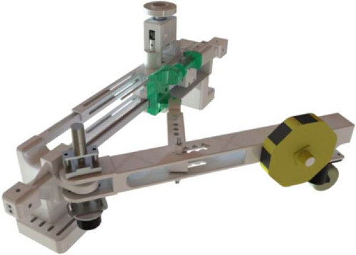
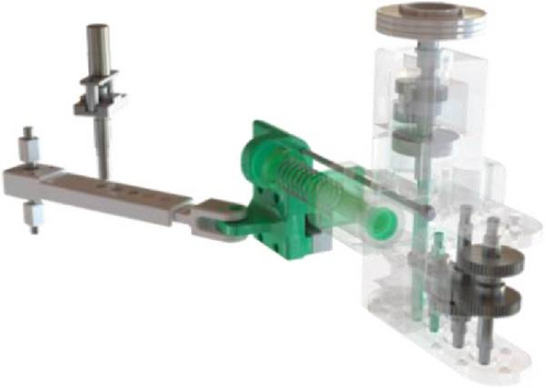
In engineering applications, structural simplification can be achieved through vehicle body equivalent substitution. When integrating the energy harvester with automobiles, only core functional modules need to be retained, including linkage assemby, active slider component, driven slider component, gearbox, flywheel assemby, and hinge motor component, as shown in Figure 17. The initial total weight of the core module during bench design phase reached 5.203 kg (Table 4) due to overdesign. Through structural improvements of mounting bodies, material substitution, and optimized bearing/slider selection, the weight has been reduced to 2.744 kg. Further weight reduction can be achieved through topology optimization and lightweight design.
| Component name | Mass before lightweighting (g) | Mass after lightweighting (g) |
|---|---|---|
| Linkage assemby | 283 | 283 |
| Active slider component | 753 | 433 |
| Driven slider component | 1894 | 566 |
| Gearbox | 930 | 788 |
| Flywheel assemby | 640 | 398 |
| Hinge motor component | 703 | 276 |
| Sum | 5203 | 2744 |
This solution demonstrates significant advantages in special engineering scenarios, particularly suitable for nonelectrifiable remote areas, aging industrial zones, and enclosed structures. Its technical value lies in self-powered sensor functionality, offering higher economic value compared to mere energy consumption reduction. Modular design combined with standardized production processes reduces manufacturing costs and achieves economies of scale, while eliminating battery replacement and manual wiring requirements effectively controls maintenance costs. The minute-level continuous power supply capability meets sensor energy demands in enclosed
5. Conclusion
This study proposes a novel kinetic energy harvesting device for vehicle doors by integrating a crank-slider mechanism with a rack-and-pinion structure, incorporating a hinge-type AC generator and a flywheel DC generator. Leveraging an innovative two-stage motion amplification mechanism and delayed meshing design, the system effectively avoids the load effect inherent in conventional door energy harvesters, while ensuring flywheel energy storage and continuous power generation post-closure. Comparative analyses of rigid and flexible optimized designs were conducted using orthogonal testing to systematically evaluate key parameters, demonstrating the superior performance of the flexible configuration.
For the rigid collision structure, the average electrical energy output ranges from 23.65 to 65.25 mJ across selected parameter combinations, with the crank-body angle at the rack-pinion meshing moment exhibiting the most significant influence on output performance. In contrast, the flexible design demonstrates more balanced and enhanced performance, achieving an average energy output range of 35.96–73.79 mJ. Optimized parameter validation confirms a 13% performance improvement of the flexible design over the rigid counterpart, effectively mitigating the negative impact of mechanical shocks. Application tests with temperature-humidity sensors demonstrate that a single door closure enables minute-level continuous power supply, verifying the device’s feasibility for wireless sensor networks. Furthermore, the proposed arc-shaped linkage design eliminates leg interference during passenger ingress/egress.
- 1.
Real-world validation: Collaborate with automotive manufacturers to establish multi vehicle testing platforms for quantifying dynamic performance under actual door operation cycles.
- 2.
Long-term durability: Investigate wear characteristics of gear-rack systems under high frequency operation and develop durability enhancement strategies using self-lubricating materials and sealed structures.
- 3.
Friction dynamics optimization: Integrate surface modification technologies (e.g., polytetrafluoroethylene coating technology [PTFE coating]) with finite element simulations to optimize load distribution in slider-rail systems.
- 4.
Hybrid energy pathways: Explore electromagnetic-mechanical hybrid transmission mechanisms to improve low-frequency-to-high frequency energy conversion efficiency.
These efforts will strengthen the integration of theoretical models and engineering practices, providing technical support for self-powered sensor nodes in intelligent transportation systems.
Conflicts of Interest
The authors declare the following financial interests/personal relationships which may be considered as potential competing interests: Weiqun Liu reports financial support was provided by National Natural Science Foundation of China.
Author Contributions
Zelong Zhao, Imdad Ullah Khan, and Junchao Zhuo contributed equally to this work.
Funding
This work is supported by the National Natural Science Foundation of China (Grants 52275574 and 52375131).
Acknowledgments
This work is supported by the National Natural Science Foundation of China (Grants 52275574 and 52375131).
Open Research
Data Availability Statement
The data that support the findings of this study are available on request from the corresponding author. The data are not publicly available due to privacy or ethical restrictions.


