Structural Design and Simulation Study of the Hydrogen Iodide Decomposition Reactor in the Thermochemical Iodine–Sulfur Cycle for Hydrogen Production
Abstract
Hydrogen, as a zero-carbon energy carrier, plays a pivotal role in global decarbonization efforts. The iodine–sulfur (I–S) thermochemical cycle stands out for its high efficiency and scalability in water-splitting hydrogen production, with the hydrogen iodide (HI) decomposition reaction being the critical step governing overall hydrogen yield. Existing HI decomposition reactors often rely on energy-intensive electric heating, which compromises system efficiency and economic viability. To address this limitation, this study proposes a novel shell-and-tube heat exchanger reactor utilizing high-temperature helium gas as a sustainable heat source, integrated with a catalytic reaction zone employing activated carbon. The reactor combines a preheating section and a catalytic decomposition section to optimize heat transfer and reaction kinetics. Using Ansys Fluent–based computational fluid dynamics (CFD) simulations, the impacts of structural parameters (reactor length, tube diameter, and residence time) and operational conditions (helium flow rate) on HI conversion efficiency were systematically investigated. Results demonstrate that increasing helium flow rate (up to 60 kg/h), reactor length (1450 mm), and tube diameter (38 mm) significantly enhances HI decomposition rates, achieving a 27.28% conversion efficiency and 1.364 Nm3/h hydrogen output. Notably, tube diameter emerged as the most influential design parameter due to its dual role in heat transfer area and residence time modulation. This work provides actionable insights for scaling energy-efficient HI decomposition reactors, advancing the industrial implementation of the I–S cycle for sustainable hydrogen production.
1. Introduction
Hydrogen, regarded as the “energy of the 21st century,” is recognized for its advantages, including zero carbon emissions, high calorific value, and widespread availability. These properties have attracted significant attention from researchers worldwide [1]. However, in nature, hydrogen exists in very small quantities in its free state. Several methods for hydrogen production have been developed, including steam reforming, partial oxidation, and gasification of fossil fuels and biomass, as well as water electrolysis [2]. Among these methods, the thermochemical iodine–sulfur (I–S) cycle for water-splitting hydrogen production, proposed by General Atomics (GA) in 1970, is considered one of the most promising technologies. This is due to its straightforward reaction steps, ability to integrate with nuclear and solar energy, high thermal efficiency, and ease of scalability for industrial applications [3, 4]. This cycle process consists of the Bunsen reaction, hydrogen iodide (HI) decomposition reaction, and H2SO4 decomposition reaction, with the relevant reaction equations shown below:
Throughout the entire reaction process, water, along with the intermediate products I2 and SO2, reacts at lower temperatures. These intermediate reactants undergo continuous oxidation–reduction cycles, ultimately resulting in the consumption of only water, which is decomposed into hydrogen and oxygen. The HI decomposition reaction, a key step in the I–S cycle, directly produces hydrogen. Its thermal efficiency and reaction rate are critical factors determining the overall hydrogen production efficiency of the process. Therefore, research on HI decomposition is of significant importance.
The structural design of the HI decomposer plays a crucial role in determining the HI decomposition rate. Numerical simulation is a crucial method for exploring the details of heat and mass transfer during the HI decomposition process, as these phenomena are difficult to measure directly. Researchers have extensively studied HI decomposers using numerical simulation methods. Ito et al. [5] developed a membrane reactor with Knudsen diffusion properties and simulated catalytic HI decomposition within the magnesium–iodine thermochemical cycle. Their findings revealed that hydrogen yield could nearly double compared to the equilibrium value (~0.2). They observed that optimal conversion occurs when the membrane allows permeability for both products and reactants, given specific permeation and reaction rates. Hwang and Onuki [6] carried out a theoretical investigation into the use of membrane reactors for catalytic HI decomposition in the thermochemical I–S hydrogen production process. They employed chemical vapor deposition (CVD) to fabricate a tailored silica membrane and assessed the membrane reactor’s performance by measuring the permeation rates of H2 and HI. Zhang et al. [7] designed a quartz plug-flow reactor and compared the mechanism they developed with existing models through kinetic experiments and thermodynamic calculations, investigating the effect of water on the reaction. Zhang et al. [8] developed a kinetic model for homogeneous HI decomposition in a plug flow reactor, integrating diatomic I2 into the HI/H2O vapor system. Their analysis highlighted the impact of factors such as temperature, residence time, pressure, the molar ratios of HI/H2O/I2 and HI/I2, and the findings from a sensitivity analysis on the HI conversion rate. Goswami et al. [9] conducted numerical simulations to investigate the transport processes within a packed bed membrane reactor and assessed its effectiveness in enhancing HI conversion during the I–S thermochemical cycle decomposition reaction. The study analyzed the effects of various parameters on HI conversion. Choi et al. [10] designed a straight-tube reactor for HI decomposition and employed commercial computational fluid dynamics (CFD) software to analyze the operational characteristics of HI decomposition in hydrogen production. The study analyzed various factors to assess the device’s performance in comparison to anticipated outcomes during its development. Shin et al. [11, 12] designed a packed HI decomposition reactor and integrated it with an external helium gas loop for effective heat transfer. They employed CFD software for numerical analysis, simulating and examining the flow patterns of helium, temperature distribution, and the percentage of HI thermal decomposition. Myagmarjav et al. [13] investigated the potential of a silica membrane reactor for HI decomposition through simulations. The simulation model was validated using data from an experimental membrane reactor. Through simulations, critical process parameters determining the performance of the membrane reactor for HI decomposition were theoretically investigated, including reaction temperature, total pressure on the feed and permeate sides, and HI feed flow rate. It was found that by employing a membrane reactor equipped with a tubular silica membrane, the conversion rate of HI decomposition could be enhanced to 80% or higher at 400°C—four times the equilibrium conversion rate (20%) under the same conditions. Nailwal et al. [14] analyzed the applicability of a Ta (95 wt%)–W (5 wt%) alloy membrane reactor to enhance the conversion rate of HI decomposition. The Ta–W membrane was fabricated using DC magnetron sputtering under optimized parameter settings. The Ta–W membrane was characterized using SEM-EDS and XPS analyses. HI decomposition experiments were conducted in a single-tube Ta–W membrane reactor integrated with a platinum (Pt)–alumina catalyst. A CFD model for HI decomposition using the Ta–W membrane reactor was developed with COMSOL multiphysics and validated against in-house experimental data. Additionally, 3D simulations of a multitube membrane reactor were performed to investigate the effects of feed temperature, feed velocity, outlet pressure, reactor wall temperature, membrane reactor dimensions, and tube spacing on parameter optimization. Zhao et al. [15] designed a novel U-shaped decomposer for HI decomposition. Multiphysics simulations revealed that the U-shaped reactor exhibited longer residence times and lower pressure drops compared to conventional straight reactors. The optimized experimental conditions for the U-shaped reactor were determined both experimentally and theoretically as a system weight hourly space velocity (WHSV) of 1000 h−1, an HI mass flow rate of 1.42 g/min, and a catalyst mass of 85 mg.
The choice of catalyst significantly influences the decomposition of HI, therefore, investigating the reaction kinetics of HI under various catalysts is essential for accurately simulating the catalytic decomposition process within the HI decomposer. Favuzza et al. [16] explored the performance of three commercial carbon catalysts in the HI decomposition reaction over a temperature range of 240–500°C. Based on the fitting results, a reliable value of (86.6 kJ/mol) was obtained. Extrapolation to lower temperatures (240–280°C) revealed that HI adsorption also became significant, enabling the estimation of QHI (52.7 kJ/mol) and the activation energy (Ea = 55.5 kJ/mol). The proposed mechanism indicates that atomic iodine formed on the catalyst surface serves as an autocatalyst, facilitating the decomposition of HI molecules. This establishes a unique relationship between the reaction rate and HI pressure; at lower pressures or higher temperatures, the reaction rate increases with pressure, while at higher pressures or lower temperatures, the rate may decline as pressure increases. Oosawa et al. [17] performed a kinetic analysis of HI catalytic decomposition using a flow method within the temperature range of 500–700 K. Pt-loaded activated carbon catalysts (1 wt%) and activated carbon catalysts, which had been shown to be effective in previous studies, were employed. Based on a proposed reaction scheme, the contact time-conversion relationship for both catalysts was successfully simulated. The effect of steam on the rate and equilibrium of HI decomposition was found to be negligible. Below 550 K, iodine significantly inhibited the rate of HI decomposition on the Pt-loaded activated carbon catalysts. Shindo et al. [18] measured the rate of HI decomposition on Pt-loaded γ-alumina over a temperature range of 480–700 K using a flow method. The Pt/γ-alumina catalyst was found to be effective in decomposing HI. A general rate equation was derived based on the Langmuir–Hinshelwood model, with the assumption that the surface reaction was the rate-determining step. Nguyen et al. [19] studied HI decomposition in the I–S cycle using a Pt catalyst. They derived new kinetic parameters for the decomposition reaction based on a Langmuir–Hinshelwood-type mechanism, utilizing experimental data. This kinetic model was then applied to simulate an HI decomposer with a hydrogen production capacity of 1 Nm3/h. The study further analyzed the influence of heat exchanger reactor design and feed solution composition on reactor size and heat consumption. Findings revealed that the co-flow structure required less heat compared to the counter-flow structure. Moreover, impurities and elevated water content in the feed solution resulted in increased reactor size and higher heat requirements.
Most reactors studied to date have relied on external heating (electric heating) to supply heat for the reaction. This is because most of the current experiments are still in the small-scale stage and have not taken into account the future development of actual industrialization. While this approach aligns with the current stage of research, electric heating would significantly reduce energy efficiency and increase hydrogen production costs during subsequent pilot testing and large-scale production. Moreover, electric heating has the problem of uneven heat distribution and low hydrogen production efficiency. Therefore, to meet the requirements of future industrial-scale hydrogen production systems, this paper proposes a novel heat exchanger–based HI decomposition reactor that utilizes high-temperature gas as the heat source. Ansys Fluent fluid simulation software was used to model the heat exchanger reactor, assess its performance and reliability within the hydrogen production system, and identify key parameters to optimize the reactor’s structural dimensions, thereby enhancing hydrogen production efficiency.
2. Numerical Simulation Model
2.1. Geometric Model
This paper presents the design of an HI heat exchanger reactor with a hydrogen production capacity of 1 Nm3/h, based on the I–S thermochemical hydrogen production pilot system at the State Key Laboratory of Clean Energy Utilization (CEU) of Zhejiang University, as shown in Figure 1. The reactor uses a shell-and-tube heat exchanger, with the entire structure constructed from titanium alloy. The tube side serves as the heating and decomposition area for HI, while the shell side facilitates heat exchange with high-temperature gas (helium).
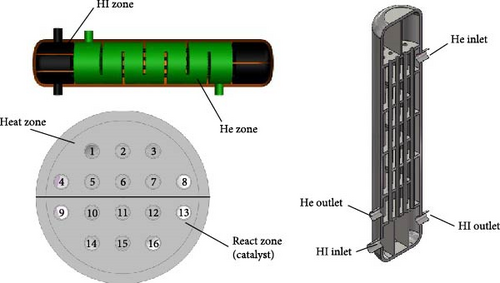
Based on the basic principles of HI decomposition, the HI heating and decomposition area is divided into two sections. The first half is designated as the fluid preheating zone, where the heat exchange tubes are not filled with catalyst. The second half is the catalytic reaction zone, where the tubes are filled with activated carbon particles serving as a catalyst. The high-concentration HI solution, after upstream distillation, enters the heat exchanger reactor through the HI inlet. It is preheated in tubes 1–8 and then enters the catalytic reaction zone in tubes 9–16, where it decomposes into H2 and I2 under the action of the activated carbon catalyst. The heat exchanger comprises 16 titanium alloy tubes, each with an internal diameter of 26 mm, a wall thickness of 2 mm, and a length of 1000 mm. The center distance between the tubes is 0.06 m. The tube bundle is enclosed within a titanium alloy shell (300 mm inner diameter, 340 mm outer diameter, and 1000 mm height, excluding the elliptical end caps) and an insulation layer is incorporated to minimize heat loss from the helium gas to the surrounding environment.
2.2. Mathematical Model
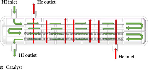
The modeling of the simulation for the HI decomposer is a multiphysics problem. A steady-state model in the fluid simulation software Ansys Fluent was used for the numerical simulation of the physical processes described. To simplify the calculations, the catalytic reaction area inside the reactor is treated as porous media. Given that the Reynolds number exceeds 4000, the flow is turbulent, and the k–ε model is employed for the relevant calculations. The fluid flow on both sides of the reactor adopts a homogeneous flow model, as shown in Figure 2. Although the catalyst loaded with Pt–palladium has greatly improved the HI conversion rate in laboratory level tests, precious metals have the disadvantage of high cost in industrial applications. In order to reduce hydrogen production costs, activated carbon–based catalyst is used as the catalyst for the reaction. To simplify the calculation, it is assumed that the catalyst particle structure is uniform and the diffusion rate is equivalent to the reaction rate. The reaction modeling within the catalyst particles adopts the single-compartment method. In the catalyst filling area, we consider it as a porous medium area during simulation, while in the preheating area where no catalyst is filled, we consider the preheating area as a nonporous medium area.
In the equation, Dp represents the particle diameter, m; and ε denotes the porosity of the particle bed. For this simulation, the activated carbon catalyst has a particle diameter of 4 mm and the porosity is set to 0.5.
In the equation, ρ represents the density of the mixed gas, kg/m3; Cp is the specific heat capacity of the mixed gas, J/(kg·K); u denotes the velocity of the mixed gas, m/s; T is the temperature of the mixed gas, K; and kt signifies the thermal conductivity of the mixed gas, W/(m·K).
In the formula, ε is the porosity of the particle bed.
In the equations, P represents the fluid pressure, KPa; xHI is the mole fraction of HI in the reaction domain; is the mole fraction of I2 in the reaction domain; Φe denotes the equilibrium conversion rate (0.21 at 700 K); Ea1 is the activation energy, which is 34.31 × 10³J/mol; and Ea2 is the heat of I2 absorption, which is −86.66 × 10⁻¹¹J/mol.
In the equation, ΔG represents the change in Gibbs free energy, which is 11.5 kJ/mol at 700 K.
In the equation, ωi represents the mass fraction of component i, xj denotes the mole fraction of component j, and Dij is the ij-component of the multicomponent diffusion coefficient matrix. Ri is the source term of the reaction.
2.3. Physical Parameters and Boundary Conditions
The working fluid inside the HI heat exchanger decomposer is a gas mixture of HI vapor, H2, I2, and water vapor. Given the relatively small changes in velocity and pressure within the decomposer, the density of the gas mixture is determined using the incompressible ideal gas model.
In the equation, ki is the thermal conductivity of component i and μi is the viscosity coefficient of component i.
In the equation, Cpi is the specific heat capacity of component i, J/(mol·K), and xi is the mole fraction of component i.
The relevant physical parameters of the activated carbon and the boundary conditions for the simulation are presented in Table 1. All other physical parameters are sourced from the Fluent database. The inlet gas mixture flow rate is determined based on the design requirements for hydrogen production of 1 Nm3/h in the hydrogen production system, corresponding to a 20% catalytic decomposition rate of a 57% HI solution. The inlet flow rate and temperature of helium are specified by the design calculations of the heat exchanger.
| Parameter | Unit | Value |
|---|---|---|
| Thermal conductivity of activated carbon | W/(m·K) | 0.6 |
| Inlet gas mixture flow rate | kg/h | 100.25 |
| Inlet gas mixture temperature | K | 393.15 |
| Mass fraction of HI at the inlet | — | 0.57 |
| Inlet helium flow rate | kg/h | 40 |
| Inlet helium temperature | K | 900 |
| Pressure | MPa | 0.1 |
3. Results and Discussion
3.1. Grid Independence Test
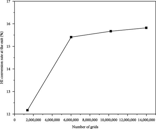
Before conducting the simulation analysis, a grid independence test was first carried out. Simulations were conducted using different grid densities to determine whether the results beyond a certain grid density were independent of the grid. These grids are referred to as fine (13,984,424 cells), normal (10,216,217 cells), medium (6,015,018 cells), and coarse (1,372,628 cells). The simulations were conducted under the same parameter configuration of the heat exchanger reactor. The results of the grid independence test, presented in Figure 3, focus on the hydroiodic acid conversion rate at the outlet. The findings demonstrate that beyond the fine grid, the conversion rate exhibits negligible variation with further increases in grid density. Consequently, a fine grid comprising a total of 13,984,424 cells was identified as having sufficient density to ensure grid-independent solutions. This grid configuration was adopted for all subsequent simulations.
3.2. The Effect of Different High-Temperature Helium Flow Rates on the Catalytic Reaction
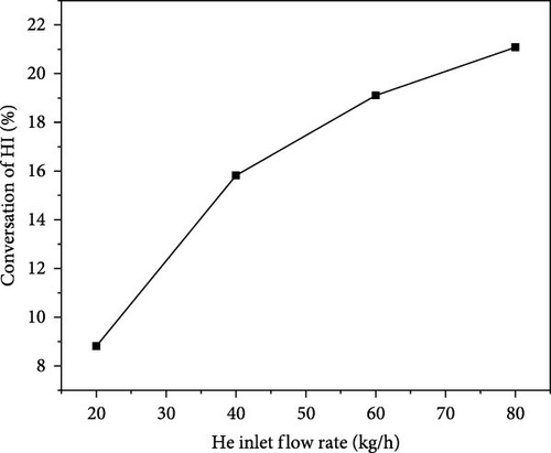
Figure 4 illustrates the relationship between the helium inlet flow rate and the HI (hydroiodic acid) outlet conversion rate. As the helium inlet flow rate increases, the HI outlet conversion rate initially rises from 8.81% to 21.08%. However, the rate of increase slows as the inlet flow rate continues to grow. At an inlet flow rate of 60 kg/h, the HI outlet conversion rate is 19.11%, which basically meets our requirements for HI conversion. Although a higher helium flow rate can increase the HI conversion rate, it also leads to energy consumption issues, which is undesirable. Therefore, the reactor design aims to maximize the HI conversion rate while maintaining low energy consumption flow rates.
To gain a clearer understanding of the changes in HI within the reactor and the heat transfer dynamics, a plane along the reactor’s axial direction was selected to analyze its temperature field and H2 distribution, as depicted in Figure 5. In the pipeline, we assume that the temperature inside the pipeline is uniformly distributed radially. When the helium inlet flow rate is 20 kg/h, the exit temperature of the HI solution in the preheating section is approximately 700 K. As the helium inlet flow rate increases to 40 kg/h, this temperature rises to 800 K. However, upon entering the catalytic decomposition section, the inlet temperature at the first layer of the reaction section decreases to around 650 K due to the endothermic nature of the reaction. According to previous research, the optimal temperature for HI catalytic decomposition is 723.15–823.15 K, which is not favorable for HI catalytic decomposition at lower temperatures. When the helium feed flow rate exceeds 60 kg/h, the HI solution in the preheating section is heated to above 800 K. Although the temperature slightly decreases at the entrance of the catalytic decomposition section, it stays above the target of 750 K. Additionally, with a helium inlet flow rate above 40 kg/h, the reactor demonstrates a relatively uniform temperature distribution within the helium channel, thereby improving heat transfer efficiency.
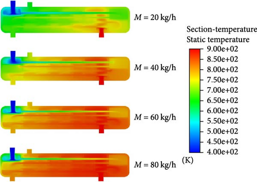
Figure 6 illustrates the distribution of the mole fraction of H2 within the reactor under varying helium inlet flow rates. When the helium inlet flow rates are 20, 40, 60, and 80 kg/h, the positions where hydrogen production begins within the reactor are located 1150, 950, 800, and 650 mm from the entrance of the catalytic decomposition section, respectively. This is because as the helium inlet flow rate increases, the HI solution more easily reaches the temperature required for catalytic decomposition, thus, shifting the H2 generation location further upstream. As the helium inlet flow rate increases, the mole concentration of H2 at the reactor outlet also rises. At a helium inlet flow rate of 40 kg/h, the mole concentration of H2 at the reactor outlet is approximately 2.1%. At a flow rate of 60 kg/h, the mole concentration at the exit of the first catalytic decomposition section already reaches about 2.1%, with the overall reactor outlet concentration increasing to around 3.15%. However, when the helium inlet flow rate is further raised to 80 kg/h, the H2 mole concentration at the reactor outlet reaches about 3.5%, which is only slightly higher than at 60 kg/h. However, excessively high inlet flow rates result in significantly higher energy consumption. Therefore, it can be concluded that a helium inlet flow rate of 60 kg/h offers the best hydrogen production performance with optimal energy efficiency.
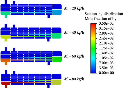
Figure 7 presents the streamlines of fluid flow inside the reactor under different helium flow rates, with color variations indicating changes in flow velocity. As shown in the figure, at a helium inlet flow rate of 20 kg/h, the fluid velocity inside the reactor remains relatively low, approximately 0.8 m/s. As the helium inlet flow rate increases, more yellow lines, indicative of higher flow velocities, become visible. When the helium inlet flow rate reaches 80 kg/h, red streamlines appear inside the reactor, indicating that some fluid velocities have reached nearly 4 m/s. However, excessively high gas flow rates can impact the pressure inside the reactor and cause some damage to the reactor itself, so the fluid velocity must be controlled within an appropriate range.
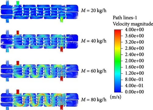
Furthermore, it can be observed that as the helium inlet flow rate increases, the fluid velocity within the tube side also rises. According to Bernoulli’s equation, this is due to the increase in fluid temperature inside the tube, which reduces the fluid’s viscosity, leading to reduced resistance to movement and increased flow velocity under the same conditions. The increase in flow velocity reduces the residence time of the HI solution inside the tube, which in turn reduces the decomposition efficiency. This explains why the increase in the mole fraction of H2 slows down.
Considering both energy consumption and internal pressure within the reactor, in order to achieve the highest possible HI decomposition rate, a helium inlet flow rate of 60 kg/h is suggested.
3.3. The Effect of Different Reactor Lengths on the Catalytic Reaction
Here, V is the volume of the reactor, which in this paper refers to the volume of HI solution passing through, and Q represents the volumetric flow rate of the HI fed in.
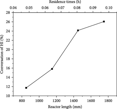
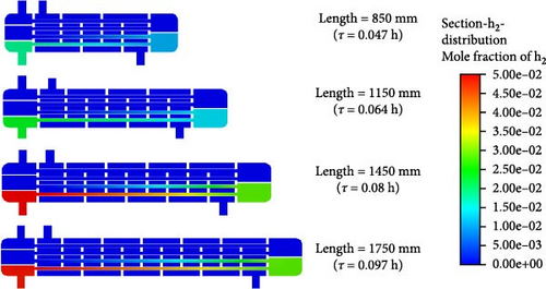
By maintaining other parameters constant (reactor diameter = 300 mm, baffle spacing = 150 mm, helium inlet flow rate = 40 kg/h, etc.), the impact of reactor length was also investigated. The effect of reactor length on the catalytic reaction was examined by varying the reactor lengths to 850, 1150, 1450, and 1750 mm (with corresponding baffle quantities of 4, 6, 8, and 10, respectively). The corresponding residence times are 0.047, 0.064, 0.08, and 0.097 h. Figure 8 illustrates the impact of varying reactor lengths on the catalytic decomposition rate of HI. As the reactor length increases, the residence time gradually increases and the catalytic decomposition rate of HI increases from 11.73% to 26.05%. This change becomes particularly significant as the reactor length increases from 1150 to 1450 mm, which corresponds to an increase in residence time from 0.064 to 0.08 h. During this adjustment, the catalytic decomposition rate improves from 15.82% to 24.14%, representing a significant rise of 52.6%. However, as the reactor length increases from 1450 to 1750 mm, leading to a rise in residence time from 0.08 to 0.097 h, the rate of increase in catalytic decomposition decreases significantly to 7.9%. This is because the longer the length of the reactor (the longer the residence time), the closer the actual conversion rate will be to the thermodynamic equilibrium conversion rate, resulting in a gradual slowing down of the conversion rate change towards the thermodynamic equilibrium conversion rate. Therefore, we can conclude that when the reactor length is 1450 mm, the HI catalytic decomposition efficiency meets the design requirements. Further increasing the reactor length has little impact and may result in an overly long reactor, leading to increased energy consumption and reduced cost-effectiveness.
Figures 9 and 10 depict the distribution of temperature and velocity fields within the reactor under varying reactor lengths. As shown in Figure 9, the feed fluid reaches 750 K at the outlet of the preheating section, but a temperature drop occurs when the fluid enters the catalytic reaction section. This is because the decomposition of HI is an endothermic reaction that requires the absorption of a significant amount of heat. When the reactor lengths are 850 and 1150 mm, with residence times of 0.047 and 0.064 h, respectively, the temperature of the reaction fluid is around 700 K after passing through the first catalytic reaction section. This suggests that the residence time of the reaction fluid is insufficient, which hinders the catalytic decomposition of HI and adversely impacts the decomposition rate.
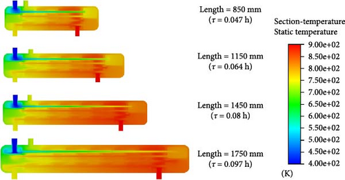

However, when the reactor lengths are 1450 and 1750 mm, with residence times of 0.08 and 0.097 h, respectively, the fluid temperature in the middle of the first catalytic reaction section reaches around 750 K, which meets the design expectations due to the adequate residence time. Notably, when the reactor length reaches 1750 mm, the fluid temperature at the reactor outlet shows a slight decrease. This is because the reactor is too long, causing the temperature of the heated fluid to exceed that of the heating fluid, which leads to the HI solution and its products heating the helium gas.
As illustrated in Figure 10, with an increase in reactor length, the flow velocity of the HI fluid at the outlets of the first and second preheating sections gradually rises. As the reactor length increases from 850 to 1150 mm, the outlet flow velocity of the reactor rises from 1.6 to 2 m/s. However, as the reactor length is further increased, the outlet velocity decreases to 1.6 and 1.2 m/s. This is due to the thermal compensation phenomenon discussed earlier.
At a reactor length of 1450 mm, it can be observed that the flow velocity inside the second catalytic reaction section is lower than at 1150 and 1750 mm conditions. A lower flow rate allows the HI fluid to fully contact the catalyst surface, making the reaction more thorough. This situation occurs because, at the 1450 mm condition, thermal compensation has already occurred, and since its temperature is lower than that of the 1750 mm condition, its flow velocity is also lower compared to the 1150 and 1750 mm conditions.
To better understand the hydrogen production inside the reactor, Figure 11 shows the mole fraction of H2 across different sections. It can be seen that regardless of reactor length, the position where hydrogen starts to form remains at 500 mm from the entrance of the catalytic reaction section. However, as the reactor length increases, the fluid’s residence times and its contact time with the catalyst are extended, which ultimately leads to an increase in hydrogen production. As the reactor length extends from 850 to 1450 mm, the mole fraction of H2 at the outlet increases progressively. However, when the length is further extended to 1750 mm, the outlet mole fraction of H2 is similar to that at 1450 mm. Therefore, we conclude that a reactor length of 1450 mm achieves the best catalytic efficiency with lower reactor costs.
3.4. The Effect of Different Heat Exchange Tube Diameters on the Catalytic Reaction
In addition to the helium inlet flow rate and reactor length, the diameter of the heat exchange tubes impacts the heat exchange area and the residence time of the reaction, thereby affecting the catalytic reaction efficiency. By keeping the reactor length constant at 1150 mm and the helium inlet flow rate at 40 kg/h, we varied the diameter of the heat exchange tubes (with corresponding adjustments in reactor size) to investigate their impact on the catalytic reaction within the reactor. The heat exchange tube diameters were set to 19, 25, 30, and 38 mm, corresponding to reactor diameters of 190, 250, 300, and 380 mm, respectively.
Figure 12 illustrates the impact of varying heat exchanger tube diameters on the HI catalytic decomposition rate. As the heat exchanger tube diameter increases, the HI catalytic decomposition rate rises from 1.42% to 24.45%, with an increase of up to 1621%. It is clear that when the heat exchanger tube diameter is less than 30 mm, the HI decomposition rate remains below 15%. At tube diameters of 19 and 25 mm, the catalytic decomposition rates are only 1.42% and 8.7%, respectively, indicating a slow decomposition process. Therefore, to achieve a better decomposition rate, the heat exchanger tube diameter should be above 30 mm and the reactor diameter should be 300 mm.
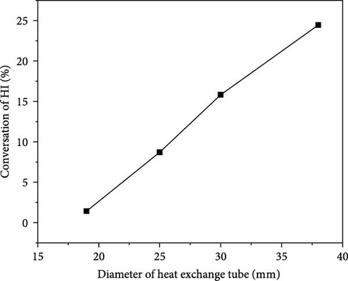
Figure 13 shows the changes in the internal temperature field, velocity field, and H2 distribution within the reactor as the heat exchanger tube diameter varies. From Figure 13a, it is observed that when the heat exchanger tube diameter is 19 mm, the fluid temperature inside the tube remains around 700 K, which is inadequate to achieve the required decomposition temperature. In Figure 13b, it is evident that the small diameter of the heat exchanger tube causes the fluid flow rate inside the tube to increase. Additionally, a smaller tube diameter results in a higher flow rate of helium on the shell side, which reduces the heat exchange efficiency. Consequently, when the tube diameter is 19 mm, almost no catalytic reaction occurs and the H2 inside the reactor is nearly nonexistent.
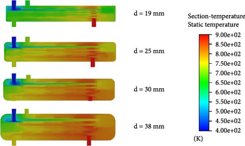
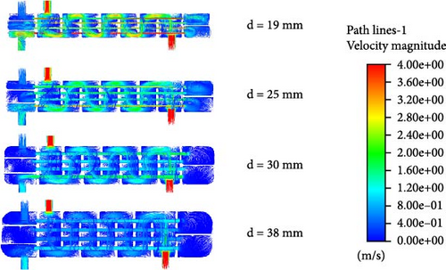
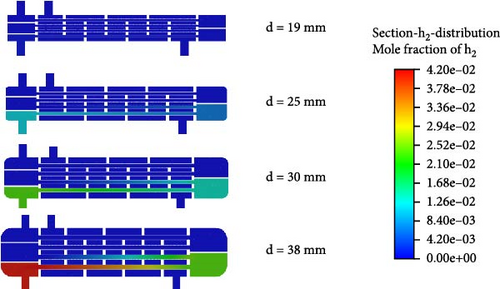
When the tube diameter is 25 mm, as shown in Figure 13c, a certain amount of hydrogen gas appears in the second layer of the catalytic reaction section, with a mole fraction of 1.26%. Compared to the 19 mm tube case in Figure 13a, the temperature in the second layer of the catalytic reaction section for the 25 mm tube reaches 800 K, meeting the required temperature for HI decomposition. Therefore, some hydrogen is produced, though the amount is small, which is due to the excessively fast flow rate.
When the tube diameter is 30 mm, although the outlet temperature of the preheating section reaches 800 K, the temperature drops to around 700 K after entering the catalytic decomposition section. As a result, HI only starts to gradually decompose at the rear of the first catalytic decomposition section. With a flow rate of approximately 2.8 m/s, the residence time within the tube is insufficient, resulting in a low mole fraction of H2 produced. At the reactor outlet, the mole fraction of H2 is only 2.94%.
When the tube diameter is 38 mm, as seen in Figure 13b, both the flow rates inside the tube and in the shell side are relatively low. The HI solution and helium have sufficient residence time and the heat exchange effect is better. From Figure 13a, it is evident that the temperature at the outlet of the first catalytic decomposition section reaches as high as 850 K. The adequate temperature and residence time further promote the HI decomposition reaction. Figure 13c indicates that, in the 30 mm case, the mole fraction of H2 at the outlet of the first catalytic decomposition section is already similar to the mole fraction at the reactor outlet. In the 38 mm case, the H2 mole fraction at the reactor outlet increases to 4.2%.
3.5. The Relative Influence of Key Factors
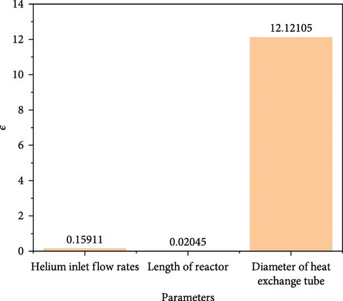
Among them, αmax and αmin denote the maximum and minimum values of the HI catalytic conversion rate, respectively, while βmax and βmin represent the maximum and minimum values of the independent parameters. Using the above research results, the ɛ value for each key factor was calculated, as shown in Figure 14. The figure indicates that helium inlet flow rate, reactor length, and heat exchanger tube diameter all positively influence the HI catalytic decomposition rate. This means that increasing the value of any of the parameters will result in an increase in the HI catalytic decomposition rate. Among them, the diameter of the heat exchanger tube has the greatest impact on the HI catalytic decomposition rate, while the reactor length has the smallest impact.
3.6. The Simulation Results Under Optimal Parameter Conditions
Based on the analysis results of the above parameters, we obtain the optimal parameters for the reactor design as follows: helium inlet flow rate = 60 kg/h, reactor length = 1450 mm, and heat exchange tube diameter = 38 mm. A numerical simulation of the HI catalytic decomposition reactor was performed based on these design parameters, the catalytic decomposition rate was found to be 27.28%, and the hydrogen production rate is 1.364 Nm3/h, which meets our requirements for the HI decomposition reaction.
Figure 15 illustrates the temperature distribution within the 16 heat exchange reactor tubes. The tube corresponding to the HI inlet position is marked at coordinate y = 0, with the tube length extending to 1450 mm. From the figure, it can be seen that the temperature variation of each layer of tubes is similar and the closer to the center of the reactor, the higher the temperature. In tubes 4–8, the temperature first rises and then falls, reaching the highest point at 1 m. This is because when the HI temperature reaches around 825 K, even in the absence of a catalyst, a certain amount of HI decomposition starts, and heat is absorbed from the surroundings. In tubes 9–13, the temperature shows a gradually rising trend, but from y = 0 to y = 1 m, the temperature remains lower than that in tubes 4–8. The presence of the catalyst intensifies the decomposition reaction, absorbing a large amount of heat. However, as it approaches y = 1.45 m, the temperature of the heating fluid (helium) rises, causing the temperature to gradually increase. In tubes 14–16 (with the flow direction of the fluid being from y = 1.45 m towards y = 0 m), the temperature shows a decreasing trend, but always remains above 825 K, which has a favorable effect on promoting HI decomposition.
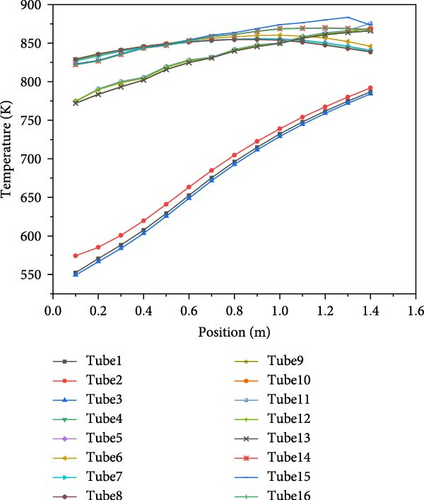
Figure 16 shows the molar distribution of hydrogen inside the catalytic reaction section, specifically in tubes 9–16. The hydrogen distribution in tubes 9–13 is consistent, as is the distribution in tubes 14–16. The hydrogen molar fraction increases as the location approaches the reactor’s center. From the figure, it can be observed that in tubes 9–13, the hydrogen molar fraction increases gradually from approximately 0.73% at the inlet (y = 0) to around 3.6% at y = 1.45 m, with a rate of increase of 0.0198 m−1. In tubes 14–16, the hydrogen concentration rises from 0.04 at the inlet (y = 1.45 m) to approximately 6.45% at y = 0, with an increase rate of 0.01689 m−1, which is slightly lower than that of tubes 9–13. This is because the higher hydrogen content inside the tubes inhibits the reaction, thereby reducing the rate of hydrogen increase.
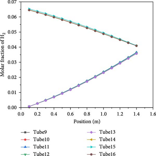
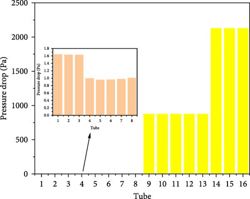
Figure 17 compares the pressure drop in the 16 tubes. In the preheating section, where only fluid heating occurs and even though some decomposition happens, the hydrogen production is relatively low, so the pressure change is not significant. The pressure drop in tubes 1–3 is around 1.6 Pa, and in tubes 4–8, it is about 1 Pa. However, in the catalytic decomposition section, due to the decomposition of HI producing H2 and I2, the pressure drop varies greatly. In tubes 9–13, the pressure drop is approximately 877 Pa, while in tubes 14–16, with higher hydrogen production and closer proximity to the reactor outlet, the pressure drop reaches around 2129 Pa.
4. Conclusion
This study focuses on the catalytic decomposition reactor of hydroiodic acid (HI) in the I–S thermochemical cycle for hydrogen production. A shell-and-tube heat exchanger reactor integrating a preheating section and a catalytic reaction section was proposed and numerical simulations were systematically conducted to analyze the effects of structural parameters and operational conditions on reactor performance. The main conclusions are as follows:
4.1. Reactor Structure and Performance Optimization
By combining a shell-and-tube heat exchanger with an activated carbon catalyst, the reactor achieved efficient heat transfer and catalytic decomposition. Using helium as a high-temperature heat source, countercurrent heat exchange between the shell-side and tube-side fluids significantly enhanced HI preheating efficiency and reaction temperature. Numerical simulations revealed that helium inlet flow rate, reactor length, residence time, and heat exchange tube diameter critically influenced HI conversion, with tube diameter optimization showing the most pronounced effect on reaction rate improvement.
4.2. Key Parameter Influence
- •
Helium flow rate: Increasing helium flow rate elevated preheating temperature and thermal compensation capacity in the reaction zone, but required energy consumption trade-offs. A helium flow rate of 60 kg/h achieved an HI conversion rate of 27.28% and a hydrogen production rate of 1.364 Nm3/h, representing optimal comprehensive performance.
- •
Reactor length and residence time: Extending reactor length (1450 mm) and residence time (0.08 h) enhanced reactant–catalyst contact efficiency. However, excessive length led to insufficient thermal compensation and increased equipment costs.
- •
Heat exchange tube diameter: Increasing tube diameter (38 mm) reduced flow velocity, prolonged residence time, and improved heat exchange efficiency, significantly boosting HI decomposition rates. This parameter emerged as the core optimization direction for reactor design.
4.3. Industrialization Potential
Under optimal parameters (tube diameter: 38 mm, reactor diameter: 380 mm, and helium flow rate: 60 kg/h), the proposed reactor demonstrated efficient and stable hydrogen production rates. This design provides theoretical foundations and design references for large-scale industrialization of the I–S cycle. By coupling external high-temperature gas sources (e.g., nuclear or solar thermal systems), the reactor avoids energy efficiency losses associated with traditional electric heating, offering advantages in low energy consumption and scalability.
This study provides critical theoretical support for the engineering application of clean hydrogen production technologies. It is expected to advance the large-scale deployment of hydrogen energy in the energy transition and contribute to achieving carbon neutrality goals.
Due to unchangeable factors, this article has the following limitations: (1) The catalyst used in this article is a commercial activated carbon catalyst, which has certain limitations on conversion rate. Subsequent research can be carried out through nanostructure modification or composite carrier design. (2) This article provides a rough modeling of some industrial processes, but further refinement can be applied to modeling the coupling mechanisms of multiple physical fields, such as the synergistic effect of flow reaction heat transfer. (3) Iodine–sulfur–hydrogen production involves the coordination of multiple steps. This article only studied and designed a catalytic reactor for HI decomposition, which can be integrated with other thermochemical cycle steps (such as sulfuric acid decomposition) for system design and energy efficiency evaluation in the future. (4) The research results of this article are numerical simulation results, which can be used for physical reactor design and verification research in the future.
Conflicts of Interest
The authors declare no conflicts of interest.
Funding
This work was supported by the National Natural Science Foundation of China (52125605) and the Fundamental Research Funds for the Central Universities (2022ZFJH04).
Acknowledgments
This work was supported by the National Natural Science Foundation of China (52125605) and the Fundamental Research Funds for the Central Universities (2022ZFJH04).
Open Research
Data Availability Statement
The data will be made available on request.


