A Novel Micro-Thermophotovoltaic Combustor of Hydrogen–Air to Enable Ultra-Lean Combustion, High Thermal Output and NO Low Emissions
Abstract
This study presents a novel micro-combustor (MC) design called micro-trapped vortex combustor (MTVC) for micro-thermophotovoltaic (MTPV) devices used in small-scale electricity generation. Traditional MC designs struggle to operate efficiently under ultra-lean regimes due to flame quenching, limiting their performance. The proposed MTVC incorporates the trapped vortex concept, inspired by aeronautical applications, to improve thermal performance and stability under ultra-lean conditions. Numerical simulations, using the Navier–Stokes and energy equations for laminar and reactive flow, are conducted to compare the MTVC with conventional micro-backward-step combustors (MBSCs) under hydrogen (H2)–air mixture combustion. The study focuses on key performance parameters such as temperature distribution, heat recirculation, flame shape, flow topology, radiative power and emissions. The results show that the MTVC can operate at an ultra-lean equivalence ratio of Φ = 0.5, while the MBSC experiences flame quenching below Φ = 0.7. The MTVC design achieves up to 26.51% higher radiative power and a 36% improvement in energy conversion efficiency compared to traditional combustor designs. Additionally, the MTVC produces 43% less nitrogen oxides (NOx) emissions, demonstrating its potential for both higher efficiency and reduced environmental impact in portable power applications.
1. Introduction
In modern life, portable electric energy needs have increased with the ongoing technological development. Traditional electric batteries (e.g., lithium ion) are no longer able to satisfy all the needs because they have reached their thermodynamic limits [1] and they have low energy densities [2]. Micro-thermophotovoltaic (MTPV) systems have been presented as suitable solution. MPTV devices are small and capable of delivering powerful energy because they burn high energy density gaseous fuels. In such a device, a micro-combustor (MC) is used to emit radiation energy that is converted by a MTPV cell into an electric current [3, 4].
MTPV combustor design requires a multidisciplinary approach, encompassing various engineering disciplines. Key design considerations include ensuring stable and efficient combustion within a confined micro-scale environment, optimising fuel and oxidiser delivery and controlling pollutant emissions. The design must maximise radiative heat transfer to the photovoltaic cells while minimising convective heat losses, all while managing the temperature distribution to prevent overheating and material degradation. The fluid dynamics within the combustor must be carefully considered to enhance mixing and heat transfer while minimising pressure losses. Furthermore, the selection of high-temperature materials and the development of microfabrication techniques are crucial for achieving a robust and efficient MTPV combustor.
Despite advancements in the field, several limitations persist in MC technology. These include combustion instability at low flow velocities [5], significant heat loss through MC walls [6], inability to operate in ultra-lean regimes and flame blow-off due to short residence times [7]. To address these challenges, various MC designs have been proposed and investigated [8], such as those incorporating bluff bodies [9], backward-facing steps [10, 11], cavities [12, 13] and porous media [14].
Regarding bluff body works, Zhang et al. [15] investigated the impact of bluff body configuration on hydrogen (H2)–air combustion characteristics. They found that employing multiple bluff bodies can significantly extend the flame’s blow-out limit velocity. Specifically, increasing the number of bluff bodies from two to four, while maintaining a constant bluff body width of 4 mm, expanded the blow-out limit from 44 to 55 m/s. Xu et al. [16] and Bagheri, Hosseini and Wahid [17] addressed numerically the effect of different bluff body shapes on H2–air flames in a MC under various inlet flow rates. For instance, Xu et al. [16] pointed out that the combustion efficiency increases from 59% to 76% with the increase of bluff body width from 3 mm to 3.4 mm. Niu et al. [18] examined the use of five trapezoidal bluff bodies with different sizes to extend combustion blow-off limits of methane–air micro-flames. The largest bluff body has led to the highest flame blow-off limit of 2 m/s. To enhance the heat flux density and average wall temperature, micro-combustion of H2–air through cylindrical pin fin array arrangements was proposed by He et al. [19]. The authors observed that the MC with staggered arrays exhibited the highest external wall heat flux, reaching 16 × 104 W/m2. In contrast, the MC without arrays displayed a lower heat flux of 7.8 × 10⁴ W/m2 at a constant volume flow rate of 96 cm3/s.
Backward-facing step and wall cavity as stabilisation options were also found effective in MC configurations as they create beneficial flow recirculation to the flame. Malushte and Kumar [20] experimentally investigated the formation of recirculation zones behind a multistep MC. Their study identified various micro-flame instabilities, such as spinning, oscillating and rotating flames. The generated flames exhibited lengths ranging from 4 to 16 mm.
To extend the flammability limits in MC devices, a novel swirl configuration combined with two backward-facing steps was proposed by Sahota, Khandelwal and Kumar [21]. The swirl configuration found to improve both the upper and lower flame stability limits by 54% and 17%, respectively. Gao et al. [22] studied the combustion characteristics of micro-cavity combustor with guide vanes and investigated the effect of different structures and installation angles of the guide vanes on the combustion characteristics. The addition of guide vanes was found to extend the flammability limit from 11 m/s without vanes to 20 m/s with vanes. Furthermore, the combustion efficiency was enhanced from 87% to 92% at a flow speed of 20 m/s.
In addition to the efforts to improve the flame stability and thermal output of MC devices, researchers also focus on the pollutant emissions. Thermal nitric oxide (NO) formation was found the most important among other nitrogen oxides (NOx) routes of H2 micro-combustion [23]. Hence, achieving low NOx emission remains a major challenge in micro-combustion. He et al. [24] investigated a H2 MC with a wavy wall through the circumferential direction forming fins with different widths. Their design is called a slinky projection shape channel. The results showed that the increase of the fins number greatly increases the exergy to reach up to 70%, while reducing NO mole fraction by up to 88% at the MC exit.
Luo et al. [25] investigated the impact of ammonia–H2–oxygen combustion on energy conversion and NOx reduction in a segmented nozzle MC through numerical simulation. They observed that increasing the H2 mass fraction from 10% to 30% led to a 13.5% increase in radiation efficiency, but also resulted in higher NO emissions. To mitigate NO emissions while maintaining high radiation efficiency, they explored fuel-rich combustion conditions. By setting H2 equivalence ratio to 1.0 and ammonia equivalence ratio to 1.2, they achieved a 13.3% reduction in NO emissions, while maintaining a radiation efficiency above 60%. Resende et al. [26] conducted a numerical study on the NOx emission of diluted H2–air flames in a circular MC. The diluent was nitrogen, and the results illustrated that the increase in dilution rate may help reducing NOx, but this has a cost on the deterioration of the thermal output of the MC.
For next-generation portable power applications, MTPV devices need to operate across variable load demands, maintain a lightweight structure, ensure thermal stability and exhibit material durability. This requires their MCs to function at both full and partial loads. Full load combustion typically occurs at stoichiometric or fuel-rich conditions (equivalence ratio, Φ ≥ 1.0), while partial load operation involves lean (0.6 ≤ Φ ≤ 0.9) or even ultra-lean regimes (Φ ≤ 0.6). Most existing MC designs documented in the literature are optimised for lean-to-rich conditions (Φ = 0.7–1.4), but encounter significant challenges in ultra-lean regimes due to flame quenching.
Some solutions [19, 21] achieved ultra-lean operation (Φ ≤ 0.6) through additions such as pin fins, bluff bodies, swirlers or porous media. However, these modifications often come at the cost of thermal efficiency and can compromise system durability. For instance, adding a bluff body can induce turbulence, stabilising the flame closer combustor’s exit. Yet, this approach has drawbacks: It raises thermal stress on the exhaust system and can lead to turbulence-induced instabilities that degrade the device. Similarly, using a porous medium stabilises the flame, but subjects it to harsh conditions that limit durability and increase the overall weight of the MTPV system.
This study represents a significant advancement by addressing the limitations of previous MC designs. It enables ultra-lean combustion at Φ = 0.5 without compromising thermal performance or system durability, an achievement previously unattained. This study proposes a novel design: the micro-trapped vortex combustor (MTVC). Inspired by aeronautical combustion systems, the MTVC incorporates a small aft-body (AB) downstream of a backward-facing step MC, creating a cavity where a trapped vortex stabilises the flame in a laminar state. This configuration enhances combustion efficiency, increases radiative power and significantly reduces NOx emissions. The MTVC’s performance is evaluated using computational fluid dynamics (CFD) simulations with a H2–air mixture under lean and ultra-lean conditions.
2. MC Configuration
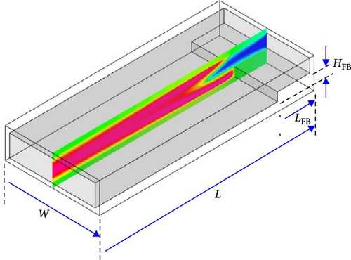
In this paper, two flat MC geometries were designed and numerically examined. The flat design is representative to side-by-side stacked MCs of an MTPV system. The first design is a conventional geometry with a micro-backward facing step (micro-backward-step combustor (MBSC)), known also as fore-body (FB), as shown in Figure 1a. This design is widely investigated in the literature [27–29] due to the flow separation induced by the FB that stabilises the flame. This design enables to perform validation with experimental data in the literature. The MC is fuelled with a perfect mixture of H2 and air, and operates under atmospheric pressure. It has the following dimensions: the height H = 1 mm, the width W = 5 mm, the length L = 10 mm, the wall thickness e = 0.2 mm, the FB height HFB = 0.4 mm and the FB length LFB = 1.5 mm.
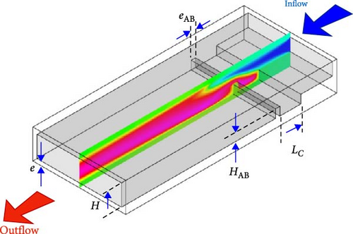
The second MC shown in Figure 1b is a modified version of the MBSC to include a second downstream body, called AB, to form a cavity. This design is inspired from propulsion and power combustion systems known as trapped vortex combustors [30] to meet the critical requirements of the combustion stability and low emissions. The present MC is called a MTVC, which takes advantages of the cavity to stabilise the flame, intensifies the combustion, delivers higher radiation power and produces less NOx compared to the MBSC design. Because in the MBSC, the flow downstream the FB separates and develops a vortex and a shear layer between the vortex and the mainstream rises. This shear layer develops instabilities in some circumstances (i.e., very high flow velocity and/or very rich mixture), which are responsible for initiating a flame blow-out [31, 32]. Alternatively, the MTVC plays a critical role in delaying the shear layer instabilities by conveniently controlling the vortex between the two bodies [30]. When the AB and the cavity dimensions are well designed, a large rotating vortex can be formed in the cavity. The vortex rotates smoothly and cannot shed out of the cavity and it is called a ‘trapped’ or ‘locked’ vortex. The trapped vortex is then capable to hold the flame and maintain the combustion from blowing out. The MTVC has the following additional dimensions: the cavity length Lc = 1.0 mm, the AB height HAB = 0.4 mm and the AB thickness eAB = e = 0.2 mm.
3. Numerical Setup
3.1. Adopted Hypothesis
It is important to summarise the adopted hypothesis in the present work with their explanation and justifications. (1) The considered flow is laminar, because the maximum velocity of the unburned mixture that will be examined is U = 18 m/s which has an equivalent Reynolds number of 1139 based on the MC height. This value will be 1.2 times higher under reacting condition to reach 1399, which is below the critical value of 2300 of the turbulent regime in ducts. (2) The flow is compressible and this is due to the density jump during the combustion (i.e., the inlet-to-exit density ratio is around 7). (3) Dufour effects are neglected because no influences were found in this kind of micro-reactive flows [33]. (4) The walls are modelled and conjugate heat transfer is considered. (5) Surface reactions are not considered because the walls are inert. (6) Structured and uniform grid is generated for both MC with a cell size of 22 μm, which is found largely sufficient to capture the thin flame and its behaviour [3, 4]. Note that previous works have adopted larger cell sizes of 25 [33, 34] and 50 μm [35] and they found satisfactory results.
3.2. Computational Method
The governing equations adopted in the present study are described as follows:
Here ‘i’ denotes the mesh cell, σ is the Stefan–Boltzmann constant, ε is the emissivity, A is the bottom wall total area, Ai is the cell area, Ti is the computed external wall temperature and Ts is the temperature of the surrounding.
The computations were done using the finite-volume solver Ansys–Fluent. The pressure-based solver was used similar to our previous works [3]. Coupled algorithm was adopted to handle the pressure–velocity coupling. A second order upwind scheme was selected to discretize of the above transport equations. The radiation energy was also considered using the P−1 model to avoid the over prediction of the combustion temperature. The convergence criteria were handled by setting the numerical residuals to 10−6 for the energy, the radiative transfer and the NOx pollutant equations. 10−5 was set for the rest of the equations. In addition, the maximum temperature at the MC centreline as well as the area-averaged temperature at the outlet were plotted during the computations to track the convergence. The stiff chemistry solver was used to accelerate the numerical combustion stability and convergence. To simulate the H2/air combustion, a detailed kinetic mechanism of 21 reactions that involve 10 species has been adopted. Relevant details of each elementary reaction are found in O’Conaire et al. [36].
3.3. Boundary Conditions
The key parameters changed in the present investigation, in order to assess their impact on the micro-flame stability and radiative power, are the inflow velocity (U) and the equivalence ratio of the mixture (Φ). For both designs MBSC and MTVC, a large inflow velocity interval was simulated from U = 0.5 to 20 m/s. Six equivalence ratios ranging from ultra-lean to stoichiometry (Φ = 0.5, 0.6, 0.7, 0.8, 0.9 and 1.0) were simulated to bluid a combustion stability diagram for both designs. A mixture of H2–air is fed to the MCs at an inflow temperature Tin = 300 K. At the MCs exit, a static pressure was imposed. At the inner side of the walls, a coupled, no-slip and zero-flux diffusion conditions were adopted. At the external side of the walls, a mixed convection and radiation condition was imposed with a surrounding temperature Ts = 350 K.
4. Validation
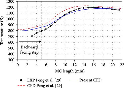
To check the suitability of the adopted numerical schemes and mathematical models described previously, two steady and unsteady simulations were conducted to perform validations with a stable combustion [29] and instable combustion regimes [37]. The steady case is a simulation of the experimental cylindrical MC configuration by Peng et al. [29]. The experimental MC is made of stainless steel and it features a backward facing step. It has a length of 22 mm, a diameter of 3 mm, a step length of 7 mm and a step height of 1 mm. It operates with H2–air mixture at stoichiometry (Φ = 1). Note that Peng et al. [29] conducted a joint experimental and numerical study of this cylindrical MC. Thus, all numerical parameters and boundary/operating conditions are kept consistent with those adopted by these researchers. Figure 2a shows comparison of the temperature profiles between the present numerical results and Peng et al. [29] experimental and numerical data. It is clearly seen that the present CFD results perform better than the numerical data across the whole axial distance. In addition, the present CFD matches well with the experimental data downstream the step where the combustion occurs. However, on the step region, there is a small discrepancy due to the unconsidered complex geometry of the metallic support that fixes the cylindrical MC from its inlet. Overall, the validation indicates that the adopted numerical method is reliable to analyse the combustion characteristics and thermal performance of the MC fuelled with H2/air.
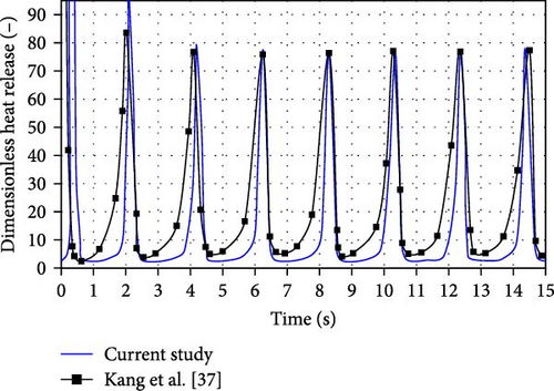
For the unstable combustion regime (unsteady simulation), the flat wall MC from Kang et al. [37] was used. This MC has a height of 0.6 mm and a length of 6 mm, demonstrating ignition and extinction behaviour under a controlled wall temperature profile. At the inlet, an inflow velocity of 0.2 m/s is applied, with a mixture temperature of T = 300 K and a stoichiometric equivalence ratio (Φ = 1) is used. Figure 2b compares the ignition and extinction behaviour of the flame using the unsteady dimensionless heat release at the centreline. The results show good agreement for this unstable combustion validation, with identical peak-to-peak amplitude and oscillation frequency of 500 Hz. The only difference is a slight shift in the HR peaks, which is expected due to the different ignition methods used in each study. In the present case, ignition occurred via a spatial patch of high temperature, while the original study used a spatial patch of heat addition.
5. Results and Discussions
5.1. Stability Diagram
To explore the micro-flame stability within both the MBSC and MTVC configurations, a parametric study was conducted by changing both U and Φ. A combustion stability diagram was built and then plotted in Figure 3. Note that rich combustion conditions (i.e., Φ > 1) were not considered to avoid high fuel consumption and high emissions. It is shown that both configurations achieve a stable combustion within the range of Φ = 0.7–1.0, and velocities of 2–18 m/s. However, when Φ < 0.7, flame blow-out occurs in the MBSC configuration due to the lack of good mixing between the fresh lean fuel–air mixture and the burned gases. On the contrast, the MTVC extends the combustion stability to a wider range of lean equivalence ratios and achieves a stable combustion even at ultra-lean condition (i.e., Φ = 0.5) and extends the lower inflow velocities range up to U = 0.5 m/s. This significant operability improvement is due to the cavity that increases the flow residence time and promotes a trapped vortex that enhances the mixing between the unburned and burned gases through a large velocity gradient within that cavity. The trapped vortex hosts the flame and enables a continuous contact between the fresh and burned gases, and thus, combustion is maintained at ultra-lean condition. The flow and thermal characteristics within the cavity are discussed in the next sections.

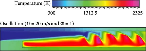
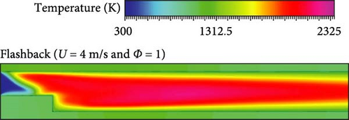
Outside the stable combustion zone, there are two main flame instabilities that appear for both designs. The first instability is denoted with the point ‘A’ (i.e., U = 20 m/s at Φ = 1), where the flame starts oscillating at high inflow speed, as shown in Figure 4a. Despite the high speed of the inflow mixture, the flow is still laminar, and this means that this oscillation is not due to transition to turbulence. It is suspected that it is due to hydrodynamic Darrieus–Landau instability, however, unsteady modelling is required to explore it, and this is beyond the scope of the current work. The second instability is indicated with the point ‘B’ (i.e., U = 4 m/s at Φ = 1), which corresponds to the flame flashback, where the flame sits on the top of the step, as given in Figure 4b. The flashback behaviour is due to the propagation of the flame towards the upstream fresh mixture at a speed higher than the inflow velocity. Moreover, the stable combustion zone is the focus of the present work.
In the following sections, three main cases of interest will be compared. The first two cases of interest are the MBSC and MTVC both at U = 8 m/s and Φ = 0.8 to assess the effect of the trapped vortex principle on the performance of the MC. They will be called lean MTVC and lean MBSC, respectively. The third case is the MTVC at U = 8 m/s at Φ = 0.5 to assess the performance of this novel MC at ultra-lean condition. It will be called the ultra-lean MTVC.
5.2. Combustion Temperature
Figure 5a,b shows the temperature contours plotted across a centre plan of both combustors at U = 8 m/s and Φ = 0.8. The inflow velocity and equivalence ratio were chosen to be in the mid-range of the combustion stability diagram reflecting the optimal performance (i.e., medium flow speed for stability and lean combustion for low emissions). For the MBSC case (Figure 5a), high temperature is reached downstream the FB indicating that the combustion is stabilised at this location, as expected from this backward step configuration. The maximum temperature of this configuration is 2192.6 K. For the MTVC case (Figure 5b), the temperature gradient is affected by the cavity presence, where two main high temperature regions are formed. This indicates that that flame shape and species concentrations are altered by the cavity. The first high temperature region is within the cavity and has a maximum temperature of 2133.17 K, whereas the second high temperature region is downstream the cavity and has a lower maximum temperature of 2084.00 K. This result shows that the adopted trapped vortex concept may slightly reduce the maximum combustion temperature by around 2.7% (ΔTmax = 59.43 K) compared to the baseline case without cavity. However, the maximum temperature zone looks closer to the lower wall of the MTCV case compared to the MBSC case. This suggests that the lower solid wall region of the MTVC has higher temperature as it will be proven later when discussing the thermal performance of these micro-reactors. Moreover, the MTVC case is capable of operating at ultra-lean condition of Φ = 0.5 at the same inflow velocity (U = 8 m/s), as shown in Figure 5c. It can be seen that the cold mixture region (blue gradient) is extended up from the inlet to the mid region of the combustor compared to the case of Figure 5b, as indicated by the black dots. This is due to the increase in the density of the mixture when decreasing the equivalence ratio (i.e., more dense air compared to less dense fuel) at the same inflow speed, which leads to an increase in the mass flow rate of the mixture. Moreover, the decrease of the equivalence ratio from 0.8 to 0.5 results in decreasing the combustion temperature that reaches a maximum value of 1933.71 K within the cavity, which is around 9.37% of temperature drop. This drop at ultra-lean regime is beneficial when an operation at partial load is required for the MTPV device. In addition, at low partial load, the MC is expected to generate a very low NOx emission, in particular the thermal NOx due to the temperature drop as it will be revealed later.
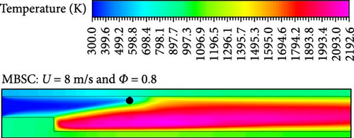
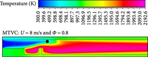
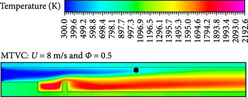
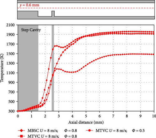
Figure 6 shows comparison of axial profiles of the temperature at the radial distance y = 0.6 slightly above the centreline of the MCs. Through the region above the step (i.e., x = 0 to x = 1.5 mm), the lean MTVC case (Φ = 0.8) shows higher temperature compared to the other two cases and this is due to the higher heat recirculation from the cavity towards the solid step (FB). Above the cavity (i.e., x = 1.5 to x = 2.5 mm), the same case (MTCV with Φ = 0.8) shows a steep temperature profile indicating the formation of a closer flame towards the inlet compared to the other two cases. For example, at x = 2.5 mm, the temperature reaches 1590.97, 1058.05, and 1040.92 K for the lean MTVC, lean MBSC, and ultra-lean MTVC, respectively. The presence of the AB in the MTVC design has its effect on the temperature profile, where it drops from its peak at x = 2.8 mm by 8% and 9% at x = 3.1 mm and x = 4 mm for the lean MTVC and ultra-lean MTVC cases, respectively. Downstream the mentioned locations, the temperature rises again to reach new high values suggesting the presence of a second reaction zone downstream the cavity. The maximum temperature at the MTVC exit reaches 1952.88 and 1484.40 K for the lean and ultra-lean cases, respectively, showing a difference of 24% (ΔTmax = 468.48 K). Moreover, the temperature profile of the lean MBSC case shows a typical profile that can be found in conventional micro-channel designs, where the temperature rises smoothly till it forms a plateau (i.e., T = 1914 K from x = 6 mm to the exit at x = 10 mm).
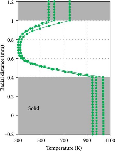
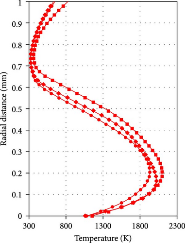
To further investigate the heat recirculation from the cavity towards the solid step, radial temperature profiles are plotted at two different axial locations, x = 0.75 mm (across the solid and fluid regions) and x = 2 mm (at the cavity) and provided in Figure 7. The axial locations are shown in Figure 7a with a schematic representation of the heat transfer direction from the cavity to the lower solid regions. It can be seen that the temperature of the solid walls is not the same for the three investigated cases as expected (Figure 7b). It seems that the MTVC cases have higher temperature than the MBSC case due to the flame presence within the cavity, which increases the heat transfer towards the solid walls in this region. At the solid step, the temperature takes the values 748.94, 615.13 and 567.25 K for the lean MTVC, ultra-lean MTVC and lean MBSC cases, respectively. Within the centre of the fluid region at y = 0.7 mm (Figure 7b), the temperature cools down due to the cold inflow, however, near the walls it increases due to the heat exchange with the hot walls. In addition, the upper solid wall is also affected by heat recirculation and both MTCV cases have higher temperature than the MBSC case. At x = 2 mm (Figure 7c), the temperature profiles take an ‘S’ shape with high temperature within the cavity and relatively low temperature above the cavity. The maximum temperature of the MTVC cases is shown taking place at the same radial location y = 0.2 mm, which is 2097.31 and 1930.55 K for the lean MTVC and ultra-lean MTVC, respectively. This result indicates that the flame has the same behaviour at this location within the cavity despite the difference in the equivalence ratio. For the MBSC case, the location of the maximum temperature (Tmax = 2022.64 K) is a bit lower, which is at y = 0.16 mm. This indicates that the cavity promotes more intense local flame leading to a high temperature with an increase of 3.5% (ΔTmax = 74.67 K) compared to the backward step case at the same equivalence ratio. Overall, it can be said that the heat recirculation induced by the trapped vortex concept is beneficial to the thermal performance of the MC as the higher heat transferred to the walls will then generate higher thermal radiation to the photovoltaic cell.

5.3. Flame Shape
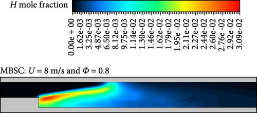
Figure 8 depicts the flame shape of the three cases of comparison visualised using the H-radical mole fraction contours. The flame shapes observed in the three cases (lean MBSC, lean MTVC and ultra-lean MTVC) vary significantly based on the flow structure and equivalence ratio. In the lean MBSC case, the flame is flat and inclined, attached at two points and stretches from the step edge to the upper wall at around 5 mm. The flame is intense (orange to red) near the step due to high shear, with a total flame length of 3.1 mm. The flame shape is influenced by the high shear forces at the step corner. These forces cause intense mixing of the incoming fresh air and burned gases, stabilising the flame at the step. The flame remains flat and stretched because the shear forces maintain a stable position at the step.
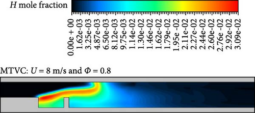
In the lean MTVC case, the flame takes a curved shape and is attached at three points, extending from the step edge to the AB and curving near the upper wall at around 4.5 mm. This flame is intense across its entire length, with a flame length of 2.5 mm. The trapped vortex design enhances the shear region between the cavity vortex and the surrounding flow, leading to a more intense and stable flame. There is a secondary vortex formed by the AB (as it will be explained and shown in the next session) that accelerates the flow and induces additional shear, which helps to stabilise the flame and increases its intensity across the entire length.
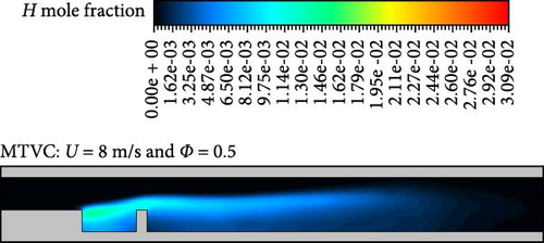
In the ultra-lean MTVC case, the low equivalence ratio (Φ = 0.5) reduces the flame temperature and intensity, elongating the flame to 6.17 mm due to the reduced heat release and lower combustion efficiency. At this regime, elongated vortices are generated and provide more time for the flame to stabilise along the combustor and the lower flow velocity of this regime leads to a broader and flatter flame.
5.4. Flow Field
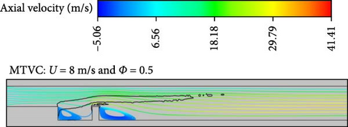
To better understand the flame behaviour and its relationship with the high flow shear regions discussed earlier, it is essential to examine the flow field across the MCs. In these configurations, cavity structures [16, 22] and wall-attached bodies [38] play a significant role in shaping the flow field, which in turn affects the combustion process. These features can generate recirculation zones and shear layers that promote the mixing of fuel and air, leading to more efficient and stable combustion. For example, cavities often act as flame holders by creating recirculating zones that trap heat and reactants, sustaining combustion even at low fuel flow rates. Figure 9 presents two-dimensional (2D) streamlines at a mid-width plane for the investigated configurations, illustrating the flow field. The streamlines are colour-coded by axial velocity and a fixed value of the heat of reaction (Hr = 1.5 W) is also shown as a black line to indicate the flame location.
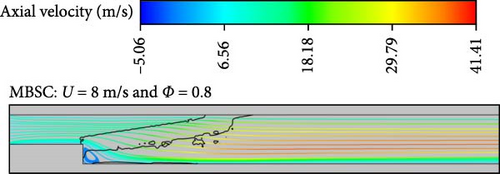
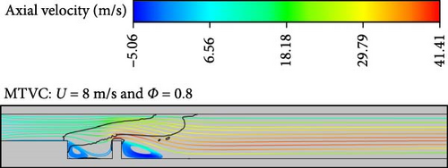
In the lean MBSC case, the flow exhibits parallel streamlines along the entire length, except at the step corner where a corner vortex forms due to the 90° geometry. The vortex has a maximum axial length of 0.35 mm and is in direct contact with the flame front. A useful metric to quantify vortex intensity is its maximum axial velocity in the backward direction, which is −0.5 m/s in this case. This metric helps compare the vortex intensity across different configurations. Inside the flame, the velocity gradient is narrow, with an average axial velocity of 16.5 m/s. Downstream of the flame, the velocity gradient increases, reaching a maximum of 38.27 m/s near the centreline. This sharp rise in velocity is caused by the density jump during combustion, and the flow velocity increases 4.8 times compared to the initial inflow. The corner vortex plays a crucial role in stabilising the flame by creating a recirculation zone that holds heat and reactants, which aids in ignition and combustion. It also prevents blow-off, especially in low-flow conditions. However, the vortex is confined and relatively weak compared to other configurations due to the geometric constraints.
In the lean MTVC case, the cavity produces a larger vortex, the trapped vortex, with a length of 0.48 mm. This results in a larger shear zone between the parallel streamlines and the rotating cavity vortex, which improves flame stabilisation. The cavity vortex has an intensity of −0.75 m/s, greater than the vortex in the MBSC case. This larger vortex promotes better fuel-air mixing, leading to more uniform combustion and reducing the risk of localised hotspots. Additionally, the presence of the AB introduces two main flow features. First, the flow accelerates at the top of the AB due to geometric contraction, increasing velocity in this region. Second, a secondary vortex forms at the AB corner, extending the shear zone. This enhanced shear zone, combined with expanded recirculation areas, contributes to higher flame intensity across the combustor length (as seen in the orange to red contours in Figure 8b). The secondary vortex has an axial length of 0.93 mm and an intensity of −5.16 m/s, which is 6.8 times greater than the cavity vortex intensity. This larger vortex generates significantly more shear, further enhancing mixing and flame stabilisation. The flame is located in a region with a large velocity gradient, having an average axial velocity of 21.52 m/s, which is 23.25% higher than in the MBSC case. This increase in local velocity is shown to raise the wall temperature (Figure 10), which is consistent with the findings of Cai, Zhao and Jiaqiang [39], who observed that wall temperature increases as the height of the bluff body rises. Downstream of the flame, the maximum axial velocity reaches 41.62 m/s near the centreline. These flow dynamics improve combustion efficiency by ensuring stable flame propagation and preventing instability caused by flame pockets or oscillations.
In the ultra-lean MTVC case, both the trapped vortex and the AB corner vortex are elongated, with maximum axial lengths of 0.7 and 1.1 mm, respectively. This elongation is due to the reduced local residence time caused by the lower equivalence ratio (resulting in higher density compared to the lean case), allowing the vortices to expand further. The cavity vortex and the secondary vortex have intensities of −0.75 and −3.1 m/s, respectively. At Φ = 0.5, the burned gases accelerate more slowly than in the lean MTVC case (Φ = 0.8), reaching a maximum velocity of 31.4 m/s, which is 24.52% lower than the maximum velocity in the lean MTVC case. The flame has a flat shape and sits on a narrow velocity gradient, with an average axial velocity of 17 m/s. This configuration, with elongated vortices and slower flow acceleration, results in a more controlled and uniform combustion process even under ultra-lean conditions. The trapped vortex continues to play a key role in flame stabilisation and the extended shear region enhances mixing and combustion, even in conditions where traditional stabilisation methods might fail. These features explain why the H2–air flame remains well-stabilized and why the combustion range can be extended to ultra-lean conditions, maintaining efficient combustion despite lower fuel-to-air ratios.
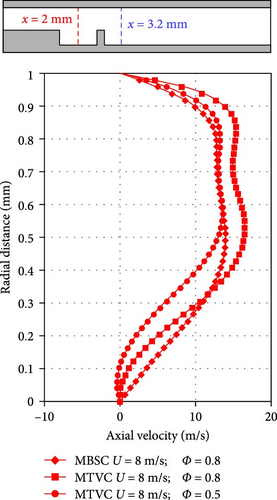
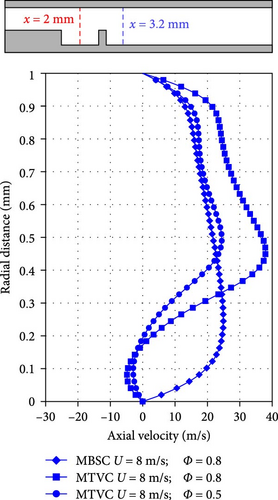
Figure 11 shows the radial profiles of the axial velocity of the three investigated cases plotted within the cavity at x = 2 mm and downstream the AB at x = 3.2 mm. The profiles provide an additional indication on how both the cavity presence and combustion regime can drastically affect the flow velocity that was responsible on altering the flame behaviour. At x = 2 mm (Figure 11a), all profiles exhibit almost a similar trend with a maximum velocity located at around the centre of the MC. The profiles of the lean MBSC and MTVC cases show positive values as they are slightly away from the vortex; however, the MTVC profile has higher velocity compared to the MBSC profile due to the difference in the vortices size. In other words, the trapped vortex of the MTVC case is larger than the MBSC corner vortex, which generates a larger blockage that leads to higher flow acceleration above the vortex. Thus, the MTVC case has a maximum velocity of 16.46 m/s, which is 15.25% higher than the maximum axial velocity of the MBSC profile. The ultra-lean MTVC profile is slightly reversed at y < 0.1 mm due to the flow recirculation of the trapped vortex. Outside the cavity (Figure 11b), the MBCS and MTVC profiles exhibit different trends. The MBSC profile is asymmetrically developed as it crosses the flame and it has a maximum value of 24.91 m/s at y = 2.45 mm, where this location is below the inclined flame. Whereas, the MTVC profiles are reversed as they cross the secondary vortex generated by the AB. The maximum velocity of the lean and ultra-lean MTVC profiles is 37.92 and 24.4 m/s, respectively, and it is as well located below the flame.
5.5. Thermal Performance
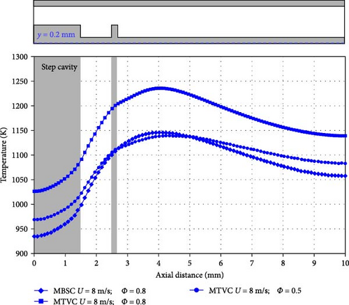
Figure 10 shows the temperature profiles along the bottom wall (at y = −0.2 mm) of the different cases to highlight the effect of the thermal diffusion through the wall on the temperature distribution. In addition, these temperature profiles are used later to get the radiative power as a thermal performance measure of the studied configurations. One can note that all the three profiles follow a similar trend with a minimum temperature below the step region and maximum temperature around the axial distance of 4 mm. The profiles show a notably pseudo-uniform trend, in contrast to the temperature profiles around the mid-height of the MC reaction zone previously shown in Figure 6. This uniformity arises primarily from the compact design of MC devices, where the high heat flux generated by combustion enables rapid heat transfer from the flame to the combustor walls, promoting even heat distribution across the wall surface. Additionally, the relatively high thermal mass of the combustor walls, in comparison to the small combustion zone, acts as a heat sink, absorbing and spreading heat more consistently. Furthermore, the MTVC design includes AB and FB features that enhance heat transfer and encourage a more uniform temperature distribution.
The lean MTCV profile shows the highest temperature values through its whole length compared to the other profiles, and this is due to the high intense flame generated by the trapped vortex cavity. The maximum temperature reaches 1235.7 K at an axial distance of 4 mm. This is lower than the 1306.9 K maximum temperature at an axial distance of 2 mm reported by Cam et al. [38] under similar U and Φ conditions, likely due to the shorter flame length observed in the current study.
Interestingly, the ultra-lean MTCV (Φ = 0.5) profile and the lean MBSC profile (Φ = 0.8) are very close to each other regardless of the difference in the equivalence ratio. This finding points to the effect of the cavity presence that alters the flame shape of the ultra-lean MTCV case and makes it elongated and parallel to the lower wall as shown in Figure 8c (i.e., the flame is closer to the lower wall compared to the lean MBSC flame that is shorter and inclined towards the upper wall). Thus, the ultra-lean MTCV profiles benefits from the elongated and parallel flame shape that improves the heat recirculation from the cavity towards the solid wall, which brings the temperature to a comparable level of the lean MBSC profile. This is evidence by the higher temperature of the ultra-lean MTCV case below the step region (i.e., T = 990.8 K at x = 1 mm) compared with the lean MBSC temperature at the same region (i.e., T = 960.4 K at x = 1 mm). Note that the effect of the heat recirculation is previously mentioned in the discussion of Figure 7. Moreover, the maximum temperatures of the lean MBSC and ultra-lean MTVC cases are 1145.7 and 1139.7 K, respectively, which are around 7.5% less than that of the lean MTVC case.
As stated earlier, the temperature at the bottom wall is useful to get the radiative power. This latter represents the amount of the heat generated by the MC from its lower surface, which is the amount of the heat that the TPV cell is exposed to. It is defined in Equation (6).
A parametric study is conducted to assess the effect of the inflow velocity on the radiative power for both the MBSC and MTVC cases at lean condition (Φ = 0.8). Thus, both the area averaged bottom wall temperature and radiative power are calculated for the range of inflow velocity U = 4; 6; 8; 10; 12; 14 m/s and plotted in Figure 12. An increase in inlet velocity results in a rise in the average wall temperature, primarily due to the higher mass flow rate of H2. For the MTVC, the temperature increases from 1044.93 K at U = 4 m/s to 1189.12 K at U = 14 m/s, whereas for MBSC the temperature increases from 1013.82 to 1129.15 K at the indicated velocities, respectively. This difference is attributed to the trapped vortex in the MTVC, which enhances combustion through increased shear forces, as previously discussed. This intensifies the combustion temperature and, in turn, boosts the heat output in the MTVC configuration. Notably, the absolute difference in radiative power between the MTVC and MBSC cases is significant, underscoring the effectiveness of the trapped vortex in not only enhancing combustion stability but also generating higher thermal output. The maximum difference in the radiative power reaches 25.38% at U = 8 m/s, which is higher than the difference in heat flux of 5.92% found by He et al. [24] between in-line and staggered pin fin arrays.
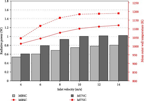
Increasing the inflow velocity above 10 m/s does not help much increasing the radiative power as the MC tends to contain a larger zone of cool mixture due to the high inflow speed, as suggested in Figure 13. Temperature contours are compared for the medium and high inflow speeds and show that the cool mixture zone (i.e., the blue region surrounded by a black line) represents 8.2% and 16.7% for the inflow velocities U = 8 and 14 m/s, respectively. The cool mixture zone contributes to reducing the heat transferred to the walls by acting as a cooling source within the MC. For example, the area-average temperature of the solid step only (the are highlighted with a red dashed box) is 1043.77 and 926.41 K for U = 8 and 14 m/s, respectively, showing the cooling effect at higher inflow speed on the step. As a result, an important amount of heat exits the combustor without being diffused through the bottom wall, where similar behaviour was found in the literature [33].


To evaluate the amount of the chemical energy contained in the H2 that is converted into useful heat during the combustion in both MCs, the conversion efficiency was calculated for the same inflow velocity range and plotted in Figure 14. The conversion efficiency is defined as:
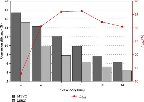
Increasing the inlet velocity has been shown to reduce conversion efficiency for both the MTVC and MBSC configurations. Specifically, as the H2 flow rate increases, a smaller proportion of the fuel’s chemical energy is converted into heat transferred through the MC outer walls. This drop in efficiency is primarily due to higher velocities reducing the residence time of reactants within the combustion chamber, thereby, limiting the extent of chemical reactions and decreasing overall heat release. Additionally, higher inflow velocities enhance convective heat losses to the combustor walls, which reduces the thermal energy available for radiative transfer to the photovoltaic cells. Consequently, low inflow speeds are ideal for maximising fuel energy conversion, as indicated by an efficiency (η) of 17.39% at 4 m/s compared to a lower 6.3% at 14 m/s. Notably, Figure 14 reveals an additional benefit of the trapped vortex concept, which significantly improves η across all inflow speeds. This improvement is especially substantial in medium inflow ranges (U = 8 and 10 m/s), where the absolute difference in efficiency (Δηabs) between the MTVC and MBSC reaches approximately 36%, consistent with radiative power trends. These findings highlight that the optimal operating range for the MTVC is in the medium velocity range.
5.6. Emission Analysis
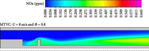
It is vital to look at the effect of the trapped vortex on NOx production during H2–air combustion. Contours of NOx in ppm are shown in Figure 15 for the three studied cases. At each of the MC configurations, high levels of NOx are located around the high temperature regions both downstream and under the flame locations (Figures 5 and 8). This suggests that the thermal NO is the dominant type of NOx generated during the reaction. Figure 15a shows that the lean MBSC case has the highest concentration with a maximum value of 0.645 ppm. It is worth remembering that the maximum temperature of the lean MBSC case is 2192.6 K. Interestingly, the lean MTVC case has also a very high temperature 2133.17 K (only 2.7% less than that of the lean MBSC case); however, its maximum NOx concentration, as indicated in Figure 15b, is 0.355 ppm which is 45% less than that of the lean MBSC case. Despite the very high temperature levels of both cases, the NOx emission of the MTVC case is significantly lower than that of the MBSC case. This significant reduction is due to the trapped vortex formed within the cavity as it increases the residence time of the burning mixture and allows more reactions to happen, which reduces the formation of NOx. In addition, downstream the AB of the cavity another small vortex forms and helps in mixing the combustion species. Increasing residence time by means of aerodynamic effects such as flow swirling or recirculation has been shown to be beneficial in reducing NOx production in the literature. Figure 15c shows that the MTVC operating at ultra-lean regime is capable of reaching a negligible level of NOx emissions with a maximum value of 0.0458 ppm maintained within the cavity. In addition, the area-average value of NOx at the MC exit is 0.352, 0.2 and 0.0044 ppm for the lean MBSC, lean MTVC and ultra-lean MTVC, respectively. The tapped vortex concept is shown to reduce this averaged pollutant emission by 43% and 98.75% under lean and ultra-lean regimes, respectively.


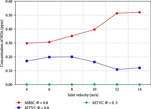
Moreover, the effect of the inflow velocity on NOx formation was also investigated and the results at the MC exit are plotted in Figure 16. It can be seen that the lean MBSC case suffers from increased NOx as the inflow velocity increases, which is 44% increase from the lowest to the highest inflow speed. On the opposite, the lean MTVC case benefits from the increasing inflow velocity to get the NOx reduced from 0.17 ppm at U = 4 m/s to 0.12 ppm at U = 14 m/s, which is 13% reduction. Results form He et al. [24] using a MC with wavy inner wall show a NOx value of 1.8 ppm at stoichiometry and U = 10 m/s, whereas the present MTVC finding show less emissions of only 0.16 ppm at U = 10 m/s and Φ = 0.8. At ultra-lean regime, the NOx formation remains nil and flat at each of the investigated inflow speeds. These results are promising compared to the NOx findings from Cam et al. [38], where at U = 12 m/s and Φ = 0.5, the NOx emissions at their combustor exit is 0.033 ppm, which is higher than the current ultra-lean result at the same flow conditions, which is 0.00113 ppm.
6. Conclusion
In this computational work, a novel MC geometry with double bodies for thermophotovoltaic applications was introduced to replace conventional backward step designs (called in this work MBSC). The double bodies form a cavity, which was expected to lock a vortex that can improve the thermal performance of the MTVC. Both configurations were fuelled with a perfect mixture of H2–air and assessed under lean condition (Φ < 0.8) and different inflow velocities (U). The performances of each configuration were evaluated, including temperatures, flame shape, flow field, radiative power, conversion efficiency and NOx emissions. The main findings of this investigation are concluded as follows: (1) The MBSC has a flame quenching issue at a lean equivalence ratio Φ ≈ 0.7, whereas the MTVC is capable of reaching an ultra-lean lean equivalence ratio Φ = 0.5. This showed that the proposed trapped vortex concept is capable of extending the combustion operability limit and can be endorsed as a promising design capable of satisfying the partial load requirement of the MTPV devices. (2) At lean conditions, the MTVC featured a shorter flame with regards to the longer flame of the MBSC, which was due to the promoted flow recirculation within the cavity that generated high shear force and intensified the combustion. The consequent effect of this was the improvement of heat recirculation towards the combustor walls. (3) The radiative power of the MTVC was shown to be up to 26.51% higher than that of the MBSC due to the improvement of the heat recirculation brought by the trapped vortex. This indicated the suitability of the trapped vortex concept to not only improving combustion stability but also to generate higher thermal output. (4) The conversion efficiency was found increasing as the inflow velocity increased, despite this the MTVC was found to be 36% efficient than the MBSC at the medium inflow velocity range, suggesting that this is the optimal range of the MTVC to operate with. (5) In terms of pollutant emissions, the MTVC significantly reduced the NOx concentration at the combustor exit by 43% compared with the MBSC at lean conditions. At ultra-lean regime (Φ = 0.5), the NOx can be brought to almost zero at a wide range of inflow speed owing to the trapped vortex that increased the combustion residence and reduced the formation of NOx. As a perspective of this work, it would be interesting to investigate the effects of the dimension of the cavity (and the FB) on the thermal performances and emissions of the MTVC configuration.
Conflicts of Interest
The authors declare no conflicts of interest.
Funding
The authors received no specific funding for this work.
Acknowledgments
The authors are thankful to the Algerian Ministry of Higher Education and Scientific Research for their generous support of this project. The authors would like to express their sincere gratitude to Nottingham Trent University for providing the computational resources that enabled this research. We also wish to thank the university for its generous support through the open access grant. We acknowledge the use of AI-based software “Gemini” to assist in polishing the language of the abstract and conclusion sections of this manuscript. The software was employed solely for language refinement to enhance clarity and readability, without altering the scientific content or interpretations. After using this tool, the author reviewed and edited the content as needed and take full responsibility for the content of the publication.
Open Research
Data Availability Statement
The data are available on request. Please contact the corresponding author.


