Metaheuristic Optimization-Based Sliding Mode Control With Modified Perturb and Observe for Controlling MPPT of a PV Interfaced Grid Connected System
Abstract
Energy is always needed more and more as civilization advances. Since the supply of traditional fuels is gradually depleting, renewable energy sources are essential for meeting energy needs. The goal of the research is to maximize the electricity that can be produced from renewable resources. Solar energy performed better than any resource regarding efficiency, cleanliness, and pollution-free nature. However, the primary drawback of the resource is its erratic nature. The system must integrate the maximum power point (MPP) tracking (MPPT) method to overcome intermittency and produce continuous optimal power. The novelty of this article is the development of a sliding mode MPPT controller for photovoltaic (PV) systems working in sunny and shaded. Also, this article introduces the meta-heuristic algorithm mountain gazelle optimization (MGO), which is incorporated to optimize the parameters of the sliding mode controller (SMC) to ensure the solar PV (SPV) MPP extraction. The stability of the mentioned control topology is assessed in terms of error parameters. The modified perturb and observe (MPb&O) method is incorporated with MGO, called (MGO-MPb&O) for performing a better tracking ability and to overcome the inability of conventional Pb&O tracking during the shaded conditions. The suggested approach looks for every maximum point across a lengthy number of cycles to find the global maximum point after introducing (MGO-MPb&O), and the results of the MATLAB/Simulink show that the algorithm performs well under the arbitrary changes of the physical parameters of the proposed system and ambient scenario. Also, the proposed hybrid (MGO-MPb&O) is compared with two other hybrid control topologies that are (PSO-MPb&O) and (cuckoo search algorithm [CSA]-MPb&O) in terms of maximum power extracted, efficiency, and convergence time of the objective function. Results depict that the proposed algorithm outperforms in every aspect and also justify the robustness of SMC. The proposed algorithm was also tested in various shading fashion (SF) in partial shading conditions for analyzing the transient response. These two performance figures for various transition instances demonstrate that the suggested MPPT algorithm can determine the global MPP for the new shading pattern (SP) when it shifts from a uniform state to a partially shaded condition at 4s (middle of the x-axis).
1. Introduction
- •
Formulation of sliding mode controller (SMC) to extract optimum power from the PV generation for the proposed structure of the PV system.
- •
Incorporating the proposed hybrid (MGO-MPb&O) for achieving true MPP with minimal settling time, less % of overshoot, and superior accuracy.
- •
The meta-heuristic optimization algorithm is evaluated based on error values, and transient responses are analyzed under various shading fashion (SF) in partial shading conditions.
- •
The suggested hybridized optimization algorithm is compared with two other hybrid algorithms based on maximum power extracted, efficiency, and objective function convergence time.
- •
Analytical assessment of the optimum power point (OPP) stability is based on parametric deviation of the PV system and thermal instability.
The entire manuscript is organized in the following manner: Section 2 depicts system modeling, Section 3 focuses on the formulation of an SMC, Section 4 discusses revolutionary hybrid algorithms to deal with unpredictability, and detailed simulation outcomes and explanations are furnished in Section 5. Lastly, some conclusions are drawn in Section 6.
2. System Modeling
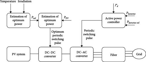
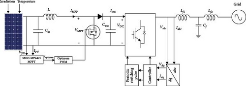
Figure 1a depicts the suggested workflow of the PV system, which consists of a PV cell coupled to a DC–DC converter, and Figure 1b shows the single-line diagram of the suggested layout. The output is connected to the inverter via a DC link. The PV cell supports the local load. The main grid is also utilized when PV low-power generation is used. The proposed structure consists of the following two essential parts:
- a.
Controller of the PV power that endeavors to extract maximum power reference from PV system concerning changing solar irradiation and ambient temperature. In this work, the DC–DC converter is controlled by PWM signals, and as a result, the PV power is adjusted to the specified value. The DC–DC converter is formulated according to the conventional formulae. Table 1 shows the parametric representation of the elements of the DC–DC converter.
- b.
The controller for exchanging power between the main grid and distributed generation (DG). Inverter control pulses and PWM are used in this study, with the shared power determined by the DC/AC converter reference value.
| Sl. no. | Parameters | Values |
|---|---|---|
| 1. | Switching frequency | 25 kHz |
| 2. | Capacitance (input) (Cin) | 158 μF |
| 3. | Capacitance (output) (Cout) | 20 μF |
| 4. | Inductance | 31.8 mH |
3. Formulation of SMC
- •
Intolerance for exogenous disturbances and unpatterned dynamics.
- •
Straightforward and adaptable controller architecture.
- •
The capacity to add an action error to the sliding manifolds and eliminate steady-state defects from the design of the SMC.
- •
Using standard power converters, order elimination, disruption exclusion, distinguishing design strategies, sensitivity to parameter alterations, and ease of implementation are all advantages of SMC.
3.1. Architecture and Formulation of SMC
The sliding mode control topology consists of two different parts. The first part is responsible for designing the sliding surface that complies with guidelines for design. The later entails look after for selecting a law of control due to which the switching area/manifold will be imploring to the state of the system.
Using asymptotic observers is an effective way to suppress chattering is to create the optimal sliding mode in the observer-included auxiliary loop.
3.1.1. Designing the Sliding Surface
3.1.2. Formulation of the Law of Control
- •
Controlling the first-order conventional sliding mode control topology.
- •
Application of high-order and low-order sliding mode control.
3.2. Strategy of PQ Controlling
Three forms of DGs exist: consisting of high frequency like microturbines, direct energy conversion sources like PVs, and varying frequency sources like wind energy conversion systems. DG units must be used with power electronic components to enable safe and reliable power system operation to link them to the main grid with sustainable consummation [41]. The controlling mode of an inverter has a significant impact on the inverter-based DGs’ performance. The DG can operate efficiently if the power converter controller is appropriately designed. As depicted in Figure 1a,b, the control mode of the inverter has a prominent impact on the performance of inverter-oriented DGs. It is evident that, for inverter-oriented DG to function in grid-associated mode, PQ state controlling is necessary for the control of the inverter. Since these parameters are predominant in the main power system, the PQ mode uses the main grid to manage the voltage and frequency.
4. Consideration of Unpredictability and Proper Algorithms
On the solar system’s I–V curves, the MPP is the point at which a PV cell operates as efficiently as possible and produces its optimum output power. Since, due to the presence of intermittent in solar power generation, the proposed sliding mode control will not be enough for drawing and sustaining optimum power. For the PV system and its power electronics to locate and maintain the operational point at the MPP, the evolutionary meta-heuristic algorithms must be incorporated by contemplating the unpredictability. The MPPT controller, which independently controls the PV array’s voltage and current, accomplishes this. This manuscript introduces the algorithm, which is the amalgamation of the MPb&O and a newly introduced meta-heuristic optimization algorithm MGO for a precise trailing of the original MPP.
4.1. MPb&O
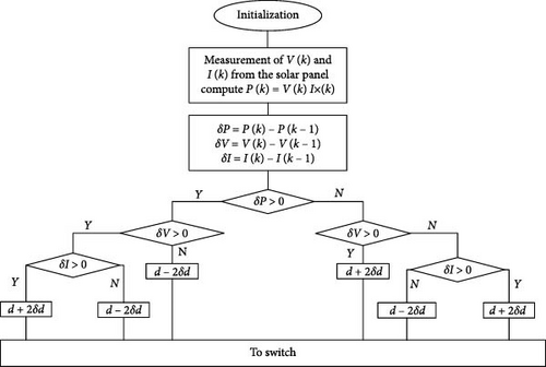
Among the different MPPT approaches, the Pb&O is a common technique. The voltage of the PV module can be measured using an implementation that relies on a voltage sensor [44]. However, this algorithm works well under uniform input conditions. When there is a variation in solar irradiation and ambient temperature, the conventional Pb&O algorithm cannot track the original MPP and creates multiple peaks around the same point. This limitation can be addressed and resolved using the MPb&O algorithm [45]. The voltage and current are sensed at the beginning, and power is computed, according to Figure 3. The MPb&O shows the advancement in the system response by introducing a third parameter, the deviation in current, in the algorithm’s flowchart. During constant irradiation conditions, the MPb&O works precisely like the conventional Pb&O. However, when the irradiation level changes rapidly, the modified version conflicts with the traditional one. When poor tracking is observed, the step size must double to intensify the tracking speed. By incorporating the procedure, the MPPT control may extricate whether the power deviation is due to the irradiation changes or disturbance in the reference potential. As a result of which, disparity from the true MPP can be abominated.
4.2. The MGO Technique
The MGO meta-heuristic optimization technique is grounded in the social interactions of untamed mountain gazelles. The gazelles are classified into four main categories such as male horde bachelor (MHB), maternity horde (MH), companionless territorial male horde (CTMH), and migration for searching food (MSF). During the tuning of the optimization process, any gazelle (Gazi) may be included as a part of these three hordes, and the improved solution may be obtained from any one of these three hordes. The MHB is the poorest solution among the entire optimizations. The best solution obtained is imitated to the upcoming repetitive iteration, and those solutions containing the least cost will be omitted from the population.
To create fresh generations of gazelles CTMH. MHB, MH, and MSF processes are applied to all gazelles. After computing the fitness of the mechanisms, the habitat is expanded to include gazelles and the entire population is organized in ascending order. The greatest gazelles are updated and saved, with the NG number of the best gazelles across all populations [45]. This algorithm performs well in the situation where there is a slow change or no deviation in the solar irradiation. But when there exist various peaks of optimum power, the algorithm may not be able to track the original MPP. Also, the initial population is selected in such a way that it may be capable of following the local optima in place of the global optima. Thus, the amalgamation of MGO with MPb&O is suggested in continuation to accomplish the benefits of both methods to achieve the original MPP. The advantages of MGO are narrated below:
The MGO algorithm optimizes each search factor and iteration using four distinct processes. Every mechanism in use has unique qualities, and every tool available today enhances MGO’s performance in every intensification and diversity component.
In order to prevent slipping into the ideal local trap, the exploration and exploitation phases run concurrently throughout all optimization stages.
Lastly, the MGO algorithm’s population update procedure guarantees that search agents with better-quality solutions are taken into account and, in the end, that all search agents are collected in a single optimal.
4.3. Formulation of MGO-MPb&O Algorithm
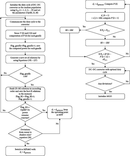
- •
ITAE is capable of getting the setting of the controller during load and set point alteration.
- •
When searching for controller parameters, particular alterations of load and/or set point can be obtained.
- •
The ITAE technique penalizes larger deviations over a longer period of time and emphasizes minimizing the error during the initial transitory reaction.
- •
Applications that require the fastest response time and settling period ought to apply this metric.
5. Simulation and Discussion
To evaluate and simulate the MPPT performance, an example PV system that includes control architecture, PWM, and different components is created in MATLAB. Table 2 shows the parametric values of the PV array.
| Sl. no. | Parameters | Specification |
|---|---|---|
| 1. | Optimum power output | 214.92 watt |
| 2. | Thevenin’s equivalent voltage (Voc/VTH) | 48.3 volts |
| 3. | Norton’s equivalent current (IN/ISC) | 8.2 amp |
| 4. | Potential at maximum point (VMPP) | 39.8 volts |
| 5. | Maximum point current (IMPP) | 7.8 A |
| 6. | Cell/module Ncell/mod) | 72 |
The framework of the simulation can be described as follows:
Framework 1: Simulation of the system under traditional Pb&O MPPT algorithm under sunny and shaded conditions.
Framework 2: Simulation of the system under the proposed MGO-MPb&O MPPT algorithm under the same scenario.
Framework 3: Analysis of the transient response of the proposed MGO-MPb&O MPPT algorithm under various SF.
5.1. Framework 1: Simulation of the System Under Traditional Pb&O Algorithm Under Sunny and Shaded Conditions
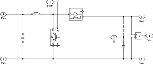
In the framework, the PV generation system configuration, which includes a PV array, step-up chopper, and controller for managing the active power, PWM signals, and load, is built in the MATLAB/Simulink environment. The implementation of the internal circuitry of the DC–DC boost chopper is depicted in Figure 5, where MOSFET, whose pulse is provided by the MPPT, is responsible for controlling the potential level. The driving signal for Pb&O is induced by the measurement of the current and voltage of the PV panel. In fact, voltage and current are the MPPT controller’s inputs, and a DC signal that produces a PWM pulse is its output. Switching of MOSFET is dependent on this pulse for the controlling of the current and voltage. In Figure 6, a block representation of the traditional Pb&O method is furnished.
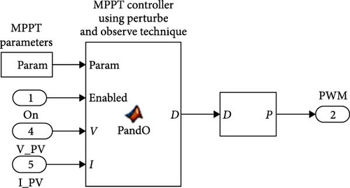
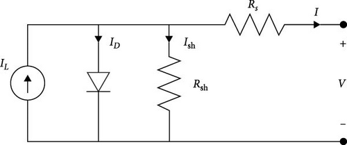
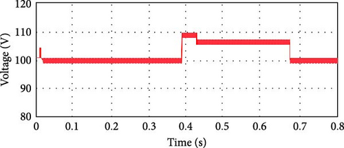
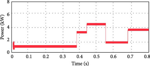
According to Figure 6, the controller receives the inputs of voltage, current, and MPPT parameters, and the PV power is calculated by the product of voltage and current. The incorporation of the delay block is responsible for measuring the deviation in power by (p(k) − p(k − 1)) where it is supposed to be maintained p(k − 1). The same logic is applicable for (v(k) − v(k − 1)). The PV array, where the point of regulating the PV cell’s diodes is constant, is structured using the MATLAB Sim-scape library. When the Pb&O control system is used to apply the attribute of deviations of power and voltage, the characteristics of the power and voltage obtained from the PV cell using the conventional Pb&O technique are shown in Figure 7. The deliberate system is designed to deliver 100 volts and 4 kW. Initially, power and voltage are adjusted in a raising approach and subsequently in a reducing approach to offer shade and sunny situations. According to Figure 7, in 0.39 s, the deviations in the power and the voltage are in the boost mode (from shaded to sunny state). During this tenure, the control arrangement of traditional Pb&O perceives the MPP that is accessed till the time. As a result, in this duration, the duty ratio of the DC–DC chopper gets reduced to enhance the voltage. In fact, when the Pb&O fails to identify the original MPP by boosting the voltage and degrading the power, it results in distance from the accurate MPP. In time 0.55 s, power is declining, and voltage fluctuation is growing, which in turn results in the position of the Pb&O controller remaining at the right half plane (RHP) of the MPP and attempting to degrade the voltage to retain to the MPP.
5.2. Framework 2: Simulation of the System Under the Proposed MGO-MPb&O Algorithm Under the Same Scenario
As stated earlier, the conventional Pb&O method is debased in the state switching from the shaded to sunny and results in loss of MPP. This also leads to abatement of power and long recovery time of MPP. To indemnify this problem, the proposed MGO-MPb&O algorithm is incorporated. In the methodology, the disturbance in voltage is responsible for achieving the deserved duty cycle, and then incorporating MGO, the MPP is reached by searching through all duty cycles. The parameters of MGO are showcased in Table 3.
| MGO parameters | Highest number of iterations | Cumulative no. of gazelles |
| 100 | 30 |
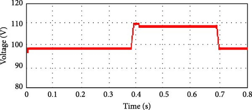
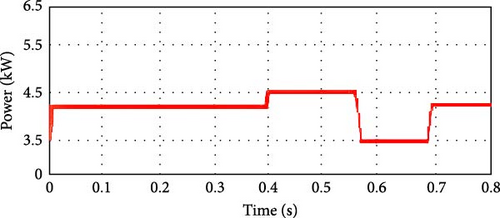
Table 4 shows theP–V data during the shaded state. Table 5 represents the variation of power and voltage of the SPV system during the mentioned state. Obviously, when switching from a shaded to a sunny state, the power is boosted up at various levels of potential, and thus the MPP is achieved at 99.98 V. The response of varying power and voltage by MGO-MPb&O is described in Figure 8. Comparing this one with Figure 7, the suggested algorithm’s fascination with less fluctuating convergence to the MPP, where the Pb&O method’s sharper responsiveness to voltage and power variation is more. It is also evident from the output that, incorporating MGO-MPb&O, the power inconstancy is mitigated as compared to conventional Pb&O which in turn results in superior tracking of accurate MPP. In Table 6 proposed hybrid MGO-MPb&O is compared to other two hybrid MPPT methods like PSO-MPb&O and CSA-MPb&O, in terms of acquired MPP, power/voltage, and duration of achieving the MPP.
| kW | Volts | kW | Volts | kW | Volts | kW | Volts |
|---|---|---|---|---|---|---|---|
| 1.321 | 102.5 | 6.410 | 102.7 | 5.567 | 103.6 | 6.351 | 103.3 |
| 1.448 | 105.7 | 5.097 | 99.0 | 4.862 | 101.3 | 5.214 | 101.1 |
| 4.342 | 105.7 | 4.876 | 101.7 | 6.345 | 104.3 | 6.513 | 102.4 |
| 2.324 | 100.3 | 6.543 | 101.2 | 3.765 | 101.1 | 5.427 | 99.8 |
| 4.897 | 105.9 | 4.167 | 99.6 | 4.891 | 103.3 | 7.011 | 101.3 |
| 2.345 | 101.7 | 6.695 | 101.9 | 6.015 | 102.8 | 6.324 | 100.01 |
| 3.345 | 104.6 | 5.824 | 99.4 | 3.132 | 99.9 | 7.214 | 102.3 |
| 5.364 | 105.4 | 6.125 | 101.9 | 5.456 | 103.5 | 7.531 | 102.8 |
| 2.545 | 101.2 | 7.315 | 101.4 | 4.178 | 99.98 | 6.375 | 99.7 |
| 5.865 | 105.1 | 5.945 | 99.5 | 6.088 | 102.5 | 6.696 | 99.6 |
| 2.739 | 101.9 | 6.129 | 101.1 | 4.761 | 100.1 | 7.100 | 99.9 |
| 3.142 | 104.1 | 6.010 | 100.09 | 3.961 | 99.2 | 7.343 | 92.0 |
| kW | Volts | kW | Volts | kW | Volts | kW | Volts |
|---|---|---|---|---|---|---|---|
| 5.521 | 102.4 | 7.465 | 101.4 | 6.765 | 101.8 | 4.895 | 103.1 |
| 1.142 | 108.5 | 6.765 | 101.8 | 6.352 | 101.6 | 5.796 | 101.1 |
| 6.898 | 103.5 | 6.856 | 99.5 | 7.320 | 103.9 | 5.796 | 100.0 |
| 6.675 | 101.8 | 6.564 | 100.0 | 6.876 | 101.6 | 6.034 | 100.0 |
| 6.354 | 107.9 | 4.076 | 106.4 | 6.087 | 102.3 | 7.135 | 100.0 |
| 6.675 | 101.7 | 6.233 | 101.2 | 6.934 | 102.1 | 6.013 | 101.3 |
| 3.243 | 101.8 | 5.768 | 101.1 | 7.232 | 102.4 | 6.244 | 101.3 |
| 6.898 | 102.6 | 5.768 | 100.0 | 6.896 | 103.9 | 5.465 | 101.0 |
| 6.675 | 101.3 | 6.434 | 104.5 | 6.976 | 101.3 | 6.689 | 101.7 |
| 7.122 | 101.0 | 7.343 | 101.4 | 7.027 | 101.5 | 7.345 | 101.6 |
| 3.654 | 106.8 | 6.768 | 101.9 | 7.656 | 102.2 | 6.675 | 101.9 |
| Sl. no. | MPPT methods | Power (kW) | Voltage (V) | Time for acquiring MPP (s) |
|---|---|---|---|---|
| 1. | PSO-MPb&O | 6.35 | 98.0 | 0.8 |
| 2. | CSA-MPb&O | 6.97 | 99.8 | 0.7 |
| 3. | MGO-MPb&O | 7.53 | 99.98 | 0.65 |
In Figure 9, the comparative analysis of the proposed algorithm with the aforementioned two algorithms is done on the basis of achieving the MPP (power/voltage) w.r.t time.
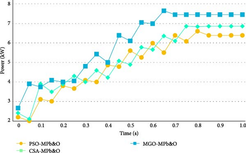
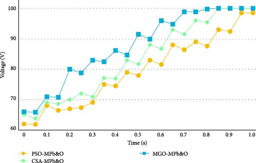
It is evident from the graphical representation that the proposed MGO-MPb&O acquires the global MPP is accomplished by the algorithm. Table 7 shows a comparative study between MGO-MPb&O, PSO-MPb&O, and CSA-MPb&O in terms of minimal settling time, less % overshoot, and a high degree of accuracy.
| Sl. no. | MPPT methods | Settling time (ms) | % Overshoot | Accuracy (%) | Rise time (ms) |
|---|---|---|---|---|---|
| 1. | PSO-MPb&O | 19.65 | 1.38 | 98 | 5 |
| 2. | CSA-MPb&O | 19.43 | 1.02 | 99.8 | 4.98 |
| 3. | MGO-MPb&O | 18.65 | 0.045 | 99.98 | 4.97 |
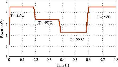
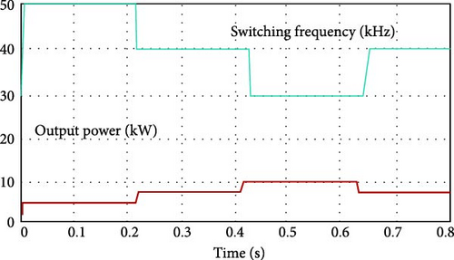
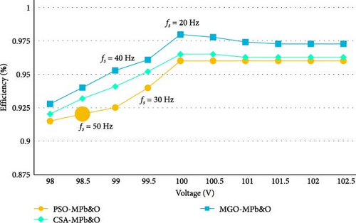
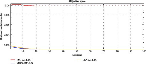
From Table 7, it is evidenced that the suggested hybrid algorithm (MGO-MPb&O) possesses the smallest settling time accompanied by the least % overshot and best accuracy compared to PSO-MPb&O and CSA-MPb&O. In Figure 10, the impact of thermal variation to achieve the accurate MPP is shown. Initially, the experiment starts with temperature 250C; then, it increases up to 550C and again comes back to the initial position. During every variation of temperature, the proposed MGO-MPb&O successfully and accurately tracks the true MPP, as furnished in the graph. The inverse proportional relation between the impact of switching frequency and the achievement of MPP of the PV system is studied in Figure 11. The suggested method’s possible output power decreases with increasing switching frequency because of increased switch loss. A comparative analysis of the efficacy of different hybrid MPPT methodologies (PSO-MPb&O) and (CSA-MPb&O) with the proposed one (MGO-MPb&O) is studied in Figure 12 due to the ever-changing switching frequency. It is evident that the efficacy of the suggested approach is superior to the other mentioned approaches w.r.t greater switching frequency. The convergence curve of the fitness function of MGO-MPb&O is showcased in Figure 13. It is observable that the proposed methodology converges in a lesser number of iterations as compared to other convetional methodologies mentioned in Table 7. Table 8 describes the optimal values of the controller gains followed by the minimum ITAE, IAE, and ISE.
| Sl. no. | MPPT methods | ITAE | ka | kb | kc | kd | ke | IAE | ISE |
|---|---|---|---|---|---|---|---|---|---|
| 1. | PSO-MPb&O | 0.059915 | 0.99976 | −0.006076 | 0.15268 | −0.10022 | 0.78675 | 2.4367e–3 | 1.0641e–6 |
| 2. | CSA-MPb&O | 0.055802 | 0.77596 | −0.78913 | 0.22918 | −0.33107 | 0.26571 | 2.4358e–3 | 7.5469e–7 |
| 3. | MGO-MPb&O | 0.051256. | 0.99998 | −0.6144 | 0.28939 | −0.08538 | 0.71229 | 2.4349e–3 | 7.5459e–7 |
5.3. Framework 3: Analysis of the Transient Response of the Proposed MGO-MPb&O MPPT Algorithm Under Various SF
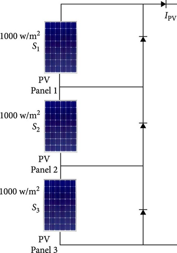
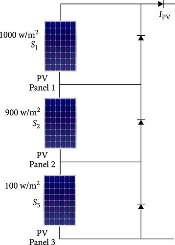
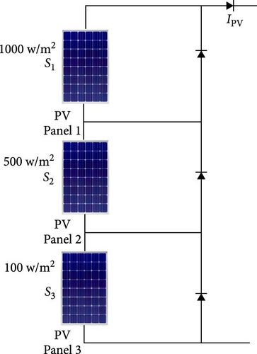
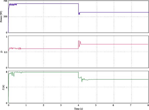
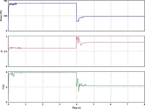
As this experiment shows, the suggested MGO-MPb&O-based MPPT can track the global MPP under both steady and transient shading patterns (SPs). We chose a few scenarios to demonstrate the tracking capability of the proposed MPPT approach because testing all nonuniform irradiance conditions is highly challenging. Table 9 and Figure 14 show the three SPs we examined. There is only one peak in the PV array’s P–I characteristic curve for SF1 since the irradiance on each PV panel is constant. There are several peaks for the remaining three SFs. Applying the MGO-MPb&O MPPT algorithm, the current in the PV string, average power, and actual power from the various shading configurations are measured and tabulated in Table 9. It demonstrates that the suggested MGO-MPb&O-based MPPT can follow the global MPP, ensuring that the power output is nearly identical to the optimal power in the three shading scenarios. This power output is based on the premise that there is no power leakage in the PV system due to wire connectivity power losses, DC–DC converter conversion efficiency, or other causes. Power cultivation will be lower than in this ideal scenario when this MPPT is used in a practical system. We looked at three scenarios to demonstrate the tracking capability of the suggested MGO-MPb&O-based MPPT algorithm in the presence of transient irradiance—Case 1: SF1–SF2, Case 2: SF switches from SF1 to SF3. For Cases 1 and 2, each PV string’s power transient characteristics, matching duty cycle, and current variable are displayed in Figures 15 and 16, respectively. These two performance figures for various transition instances demonstrate that the suggested MPPT algorithm can determine the global MPP for the new SP when it shifts from a uniform state to a partially shaded condition at 4 s (middle of the x-axis). For instance, when the case switches from SF1 to SF2 and SF1 to SF3, the power changes from 645 W to 480 W and 645 W and 344 W, respectively.
| Shading fashion | Solar irradiation (W/m2) | Theoretical value of power (W) | Measured value of power (W) | PV current at MPP (A) |
|---|---|---|---|---|
| SF1 |
|
645 | 645 | 7.8 |
| SF2 |
|
480 | 480 | 6.3 |
| SF3 |
|
344 | 344 | 4.2 |
6. Conclusion
In this manuscript, a novel combinatory hybrid algorithm is studied and validated by amalgamating a newly introduced meta-heuristic algorithm MGO with an MPb&O algorithm for sliding mode control topology for the superior tracking of the MPP in the PV generation system. Conventional Pb&O cannot keep track of a rapid ambiance change from sunny to shaded conditions. In the case of MGO, it alone obtains the local maximum point instead of keeping track of the global maximum. The shortcomings of the previously mentioned algorithms can be overcome by implementing the proposed MGO-MPb&O. This control topology is time-varying or nonlinear as they can respond to a sudden unpredicted perturbation in input parameters or dynamics of the system. From the point of view of efficacy, duration for convergence, and maximum obtainable power, the suggested algorithm proves to be the best compared to PSO-MPb&O and CSA-MPb&O. Also, the proposed methodology is the best among the other two mentioned regarding minimal settling time, less % overshoot, and accuracy. The proposed algorithm proves its superiority in partial shading conditions by analyzing the transient responses and considering three SFs. For future work, the performance of the proposed methodology can be tested and validated on some nonlinear systems considering unanticipated parameters. Many newly introduced meta-heuristic algorithms, like the meerkat optimization algorithm, osprey optimization algorithm, and transit search algorithm, can be employed with the suggested system.
Conflicts of Interest
The authors declare no conflicts of interest.
Funding
Open access funding is provided by Qatar National Library under the QNL–Wiley open access agreement. Further, this work is supported by the Qatar National Research Fund under Grant No. AICC05-0508-230001 for the project Solar Trade (ST): An Equitable and Efficient Blockchain-Enabled Renewable Energy Ecosystem – Opportunities for Fintech to Scale Up Green Finance for Clean Energy. Additional support from the Qatar Environment and Energy Research Institute (QEERI) is also gratefully acknowledged.
Open Research
Data Availability Statement
Data sharing is not applicable to this article as no datasets were generated or analyzed during the current study.


