Design of PVDF–g–PAA Binder Endowing High Sulfur Loading With Enhanced Performance of Lithium–Sulfur Batteries
Abstract
Lithium–sulfur (Li–S) batteries have received considerable attention as promising candidates for next-generation batteries because of their high theoretical energy density (≈2600 Wh kg−1). However, despite their abundant active material and high theoretical capacity, the commercialization of Li–S batteries has been hindered by several difficulties such as the shuttle effect of lithium polysulfides (LiPS). In this study, we designed poly (vinylidene fluoride)–graft–poly (acrylic acid) (PVDF–g–PAA) as a novel binder to realize high sulfur loading electrodes for Li–S batteries. The synthesis conditions of PVDF–g–PAA were controlled based on its chemical structure, mechanical properties, and electrochemical performance. The optimal structure of PVDF–g–PAA exhibited high LiPS adsorption ability compared to that of PVDF, which retained its mechanical properties. Therefore, the unit cell with a high sulfur loading of 5.7 mg cm−2 fabricated using PVDF–g–PAA yielded a high reversible capacity of 644.1 mAh g−1 after 100 cycles. Consequently, this study provides a useful approach to improve the cycling performance of Li–S batteries by modifying commercial binders, which demonstrates their practical potential for developing Li–S batteries.
1. Introduction
Lithium-ion batteries (LIBs) have rapidly gained popularity because of their superior energy densities compared to those of other existing batteries, such as Ni–MH batteries [1–6]. However, current LIBs have limitations in a wide range of applications requiring high energy densities, such as electric vehicles [7, 8]. Accordingly, researchers have focused on next-generation lithium batteries using new chemicals that deliver higher energy densities. Among them, lithium–sulfur (Li–S) batteries, which comprise a sulfur cathode and Li metal anode, have been highlighted as next-generation batteries because of their low cost, high theoretical specific capacity (1675 mAh g−1) of sulfur, and high theoretical specific energy density (≈2600 Wh kg−1) [9–16]. Despite these advantages, the commercialization of Li–S batteries presents several challenges. In particular, the shuttle effect caused by lithium polysulfides (LiPS) dissolved in an electrolyte leads to the severe corrosion of Li metal anodes and loss of active materials, which results in a rapid decrease in cycling performance [17–20].
Thus far, considerable efforts have been made to tackle these problems by improving various components of Li–S batteries. Numerous studies focused on sulfur cathodes that physically confine LiPS by infiltrating carbon hosts with different structures, including hollow carbon, porous carbon, and carbon nanotubes [21–24]. Manthiram et al. reported that a carbon-coated separator produced via the tape-casting method using super-P intercepted the diffusion of LiPS from the cathode to anode because LiPS was immobilized by carbon nanoparticles [25]. Further, from the perspective of the electrolyte, the migration of LiPS can be controlled by various factors such as the type of salt, solvent, and concentration [26]. These approaches have been used to affect the performance of Li–S batteries. Nevertheless, further improvements are still required.
Among the components of batteries, polymeric binders have received relatively less attention because they account for only a small fraction of the mass in the electrode. However, the binder plays a crucial role in maintaining the structure of the electrode with robust adherence to active materials, conductive agents, and current collectors [27, 28]. Poly (vinylidene fluoride) (PVDF) has been widely used in conventional batteries because of its numerous advantages, including excellent electrochemical stability, strong adhesion with active materials, conductive agents, and current collectors, homogeneous dispersion in an electrode slurry, and inertness against separators and electrolytes [29]. However, in Li–S battery systems, PVDF as a binder cannot sufficiently suppress the shuttle effect of LiPS because of its nonpolar fluorine atom [30, 31]. Binders containing polar functional groups such as carboxyl (−COOH), hydroxyl (−OH), and amino groups (−NH2) can interact with LiPS via strong chemical interactions in the electrode, effectively suppressing the shuttle effect of LiPS [32, 33]. Considering the various advantages of commercial binders such as electrode processability, it is necessary to modify the commercial PVDF binder with functional groups that can attract LiPS. In particular, for high sulfur loading electrodes, a large amount of dissolved LiPS is expected to increase the viscosity and concentration gradient of the electrolyte, resulting in a severe shuttle effect, which could lead to severe polarization and degraded reaction kinetics with poor cell performance [34]. Therefore, it is important to improve the performance of Li−S batteries by designing binders that can effectively absorb large amounts of LiPS.
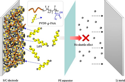
In this study, we designed a multifunctional binder by grafting poly (acrylic acid) (PAA) onto PVDF (PVDF−g−PAA) for a sulfur cathode. PAA has a carboxyl group on each monomer unit that can chemically interact with LiPS, which controls the shuttle effect during cycling [35]. Two stages of binder synthesis—dehydrofluorination and free radical polymerization—were controlled based on the mechanical properties, LiPS adsorption ability, and electrochemical performance. Consequently, 4 h of dehydrofluorination (dPVDF) and 12 h of PAA-grafting (PVDF−g−PAA (12 h)) displayed strong LiPS adsorption ability with reasonable mechanical properties comparable to those of PVDF. PVDF−g−PAA (12 h) exhibited improved cycling performance when applied to Li−S cells with a high sulfur loading of 5.7 mg cm−2, providing a discharge capacity of 644.1 mAh g−1 with a retention of 75.8% after 100 cycles at 0.3C.
2. Materials and Methods
2.1. Materials
Acrylic acid (AA), N,N-dimethylformamide (DMF, 99.8%), lithium bis (trifluoromethanesulfonyl)imide (LiTFSI, 99.95%), 1,2-dimethoxyethane (DME, 99.5%), 1,3-dioxolane (DOL, 99.8%), and lithium sulfide (Li2S, 99.98%) were purchased from Sigma–Aldrich. Potassium hydroxide (KOH), ethyl alcohol (EtOH), and N-methyl-2-pyrrolidone (NMP, 99.5% purity) were obtained from Daejung Chemicals. PVDF (KF9300, KUREHA, Japan), 2,2′-azobisisobutyronitrile (AIBN, Junsei, Japan), porous carbon (C-novel, Toyo Tanso), sulfur powder (SP 325, Midas), super-P (TIMCAL, Belgium), and lithium nitrate (LiNO3, Alfa Aesar) were used as received from the respective supplier.
2.2. Polymer Synthesis
PVDF−g−PAA was synthesized via a two-step process: dehydrofluorination, creating C═C bonds, and free radical polymerization, elongating the PAA side chains from the C═C bonds, as shown in Figure 1 [36]. In the dehydrofluorination step, 5 g of PVDF powder was added in 100 mL of 2.50 M KOH solution at 60°C, and 25 mL of EtOH was added rapidly while stirring for 1, 4, 8, 12, and 18 h, respectively. After the reaction, each powder was washed with deionized water until neutral pH, and then dried overnight at 80°C. In the free-radical polymerization step, 1 g of dehydrofluorinated PVDF (dPVDF) powder was added in 60 mL of DMF at 70°C under an N2 atmosphere, adding 0.02 g of AIBN and 1.2 g of AA monomer and stirring for 6, 12, and 24 h, respectively. After polymerization, the reaction product was washed three times with deionized water to remove residual impurities and dried in an oven for 48 h at 60°C to obtain the final products, which were called PVDF−g−PAA (6, 12, or 24 h).

2.3. Material Characterization
Fourier transform infrared spectroscopy (FT-IR, Bruker Vertex 70) was used to identify the functional groups of the polymers. 1H nuclear magnetic resonance (1H NMR, Bruker Avance III 600, 600 MHz) was employed using DMSO-d6 for analyzing the chemical structure and ratio of C═C bonds and carboxyl groups (−COOH) after the reactions at each step. Mechanical properties of the binders were measured using tensile testing (JSV-H1000, Coretech). Each polymeric binder specimen had identical dimensions: 1 cm (width) × 3 cm (length) × 100 μm (thickness). The LiPS adsorption ability was analyzed using ultraviolet–visible (UV–Vis) spectroscopy (Agilent Cary 60) at wavelengths ranging from 300 to 800 nm. The Li2S6 solution was prepared by heating a mixture of pure sulfur powder and Li2S at a molar ratio of 5:1 in a DME:DOL solution at a volume ratio of 4:1 [28]. After adding each binder to the Li2S6 solution and stirring at 25°C for 24 h, the supernatant was collected for UV–Vis measurements. The elemental composition and chemical bonding of Li metal anodes before and after cycling were analyzed using X-ray photoelectron spectroscopy (XPS, Thermo Scientific K alpha). The morphology of the sulfur cathode before and after cycling was observed by scanning electron microscopy (SEM, FEI Quanta 3D FEG and JEOL, JSM-7000 F).
2.4. Preparation of the S/C Cathode
The sulfur-infiltrated porous carbon (S-PC) was prepared in the same manner as reported in previous work [37]. Initially, sulfur powders and porous carbon were mixed in a weight ratio of 3.5:1 and subjected to ball-milling for 3 h. The mixture was placed in a teflon-lined stainless-steel autoclave and heat-treated under an Ar atmosphere at 155°C for 8 h. Then, a composite slurry for the electrode was prepared by mixing S-PC, super-P, and each binder in a weight ratio of 90:5:5 using NMP as the solvent. This slurry was homogeneously blended and uniformly coated on a carbon-coated aluminum foil current collector, and subsequently, it was dried overnight at 80°C. The sulfur loading levels of the electrodes with different types of binders were 5.7 mg cm−2. The dried S/C cathodes were roll-pressed and dried in a vacuum oven for 3 h to completely remove residual solvent and moisture.
2.5. Electrochemical Measurements
A 2032-type coin cell (NEBA, South Korea) was assembled in a controlled dry environment using cathodes, Li metal as the anode, and a carbon-coated separator. The electrolyte used in the cells was a solution containing 1.0 M LiTFSI and 0.4 M LiNO3, dissolved in a mixture of DME and DOL at a volume ratio of 4:1. A WBCS3000 automatic battery cycler (WonATech, South Korea) was used to determine the galvanostatic discharge/charge and cycle stability of each cell at voltages ranging from 1.7 to 2.6 V (versus Li/Li+). This measurement was performed at an initial rate of 0.1C three times and then cycled at 0.3C. The initial discharge capacity of the battery operating at 0.1C was used as a standard value, and the implemented initial discharge capacity was ~1200 mAh g−1, which was set as the 1C standard value. Electrochemical impedance spectroscopy (EIS) was performed to analyze the bulk resistance (Rb) of each cell before cycling and the overall resistance before and after cycling across a frequency range of 5 MHz to 100 mHz, utilizing an AC voltage amplitude of 10 mV using a VSP potentiostat (Biologic). The Rb of each cell containing different types of binders was evaluated by reducing the voltage by 0.1 or 0.2 V ranging from 3.0 to 1.6 V in the discharge process.
3. Results and Discussion
We prepared a series of dPVDFs with the dehydrofluorination time as a variable for regulating the ratio of C═C bonds, which could act as starting points for grafting. The chemical composition and structure of dPVDF were analyzed using FT-IR and 1H NMR after the first step. The FT-IR spectra in Figure S1 verify the existence of C═C bonds compared to PVDF. A series of dPVDF showed intense transmittance peaks at 1630 cm−1, representing the stretching vibration of the C═C bonds [36, 38]. The chemical structure was confirmed using 1H NMR analysis with DMSO-d6 as the solvent, as shown in Figure S2. The spectrum of PVDF showed two distinct peaks originating from the head-to-tail (htt, –CF2CH2–CF2CH2–, referred to as a peak) and tail-to-tail (ttt, −CF2CH2-CH2CF2−, referred to as a’ peak) bonds. These peaks appeared at 2.7−3.3 ppm and 2.2−2.7 ppm, respectively [39]. In a series of dPVDF spectra, a new peak (–CH═CF–, referred as b peak) at 5.5−6.5 ppm was shown, which resulted from the C═C bond formation after the elimination of HF during dehydrofluorination [40]. The increase in b peak intensity with reaction time indicates that the ratio of C═C bonds increased with prolonged dehydrofluorination time (1, 4, 8, 12, and 18 h) [36, 41]. Additionally, the quantitative analysis of the C═C bonds in dPVDF was conducted. Table S1 shows that the proton ratio of the b peak increased from 0.9% to 7.9% with a longer reaction time when comparing the proton ratio of PVDF (a and a’ peak) with that of C═C bonds (b peak) [41].
We verified the effect of the degree of dehydrofluorination on the electrochemical performance of a series of dPVDFs as binders in high-nickel cathode-based LIBs [29]. A detailed description of cathode fabrication is provided in Supporting Information. Figure S3 shows that cells with dPVDFs subjected to dehydrofluorination for up to 4 h demonstrated high capacity retention, with an average of over 90% after 100 cycles. In contrast, the other materials, including dPVDFs, which were dehydrofluorinated for more than 8 h, exhibited low capacity retention of less than 80%.
For clarifying the reasons for this result, tensile testing was performed to investigate the effect of the dehydrofluorination on the mechanical properties, and the correlation between the cycle stability and mechanical properties of the dPVDFs was confirmed. Figure S4 and Table S2 show that PVDF had the highest stress and strain values (17.7 MPa and 0.096, respectively). The increment in the C═C bond ratio of dPVDF induced a decline, with the stress values ranging from 17.4 to 9.2 MPa and the strain values varying from 0.091 to 0.033. Thus, the mechanical properties of the binders are affected by the existence of rigid C═C bonds, which lead to a reduction in stress and strain with an increase in the ratio of C═C bonds [42]. dPVDF (8 h) experienced a rapid decrease in stress and strain, which was markedly different from that of dPVDF (4 h). Therefore, the mechanical properties of dPVDF rapidly deteriorate when the reaction time exceeds 4 h in the dehydrofluorination step, thereby resulting in poor cycling performance. This indicates that 4 h of dehydrofluorination was the optimal condition.
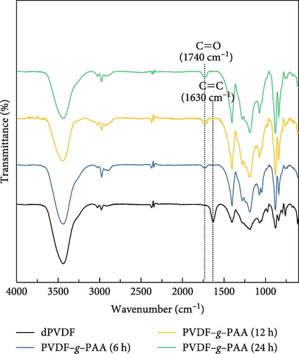
Linear PAA side chains were grafted onto the C═C bonds of dPVDF (6, 12, and 24 h) after 4 h of dehydrofluorination. The chemical compositions and structures of the binders were analyzed using FT-IR and 1H NMR, as shown in Figure 2. The FT-IR spectra reveal that the C═C bond peak at 1630 cm−1 was absent after PAA grafting, whereas the C═O peak of PAA at 1740 cm−1 emerged [36, 43]. This indicates that introducing PAA for 6 h was sufficient to break all C═C bonds, as illustrated in Figure 2a. Figure 2b shows the 1H NMR spectra of a series of PVDF–g–PAA with DMSO-d6. The C═C bond peaks (b peak) at 5.5−6.5 ppm disappeared, while the characteristic peaks of the carboxyl group (−COOH, denoted as d peak) appeared at 11.5−12.5 ppm [44]. The peaks at 1.4−1.6 and 1.7−1.85 ppm are attributed to methylene (−CH2, referred as c peak) and methine (−CH, referred as c’ peak) groups, respectively [45]. This also confirmed the successful production of PVDF–g–PAA as all C═C bonds were broken, which allowed PAA to enter the broken sites.
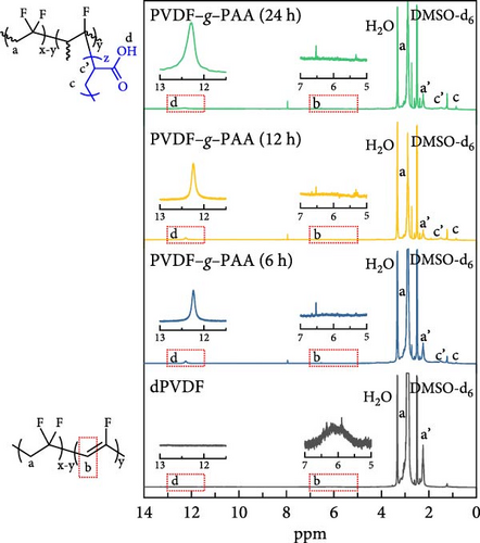
The proton ratio of a series of PVDF–g–PAA increased by 1.5%, 2.6%, and 4.0% compared to the backbone structure of PVDF depending on the PAA-grafting time (6, 12, and 24 h) (Table 1). This implies that the length of the PAA side chain increased.
| Ratio of integration area (%) | |||
|---|---|---|---|
| a (htt) and a’ (ttt) | b (C═C) | d (−COOH) | |
| dPVDF | 98.6 | 1.4 | — |
| PVDF–g–PAA (6 h) | 98.5 | — | 1.5 |
| PVDF–g–PAA (12 h) | 97.4 | — | 2.6 |
| PVDF–g–PAA (24 h) | 96.0 | — | 4.0 |
- Abbreviations: dPVDF, dehydrofluorinated poly (vinylidene fluoride); PVDF–g–PAA, poly (vinylidene fluoride)–graft–poly (acrylic acid).
Figure 3 shows an optical image and UV–Vis spectra following the LiPS adsorption test to evaluate the adsorption ability of PVDF–g–PAA. The inset image shows the LiPS solution after exposure to different binders for 24 h. Solutions with a series of PVDF–g–PAA became lighter in color than the PVDF-containing solution, and the color changed to light yellow with an increase in the PAA-grafting time. UV–Vis measurements were used to compare the concentration of LiPS present in each solution by analyzing the intensity of the absorbance peaks [28, 43]. According to the spectra, PVDF–g–PAA solutions have lower intensity than that of the PVDF solution, with a peak from the S42− species (420 nm) [47, 48]. Further, PVDF–g–PAA (24 h) exhibits the highest adsorption performance among the PVDF–g–PAA solutions, and the intensities of the peaks decrease with longer PAA-grafting time. This implies that PVDF–g–PAA has a stronger binding ability to LiPS than PVDF because of the presence of polar carboxyl groups [49]. These results suggest that the introduction of PVDF–g–PAA has the potential to effectively inhibit the shuttle effect of LiPS, which is among the main challenges of Li–S batteries, and it improves cell performance.
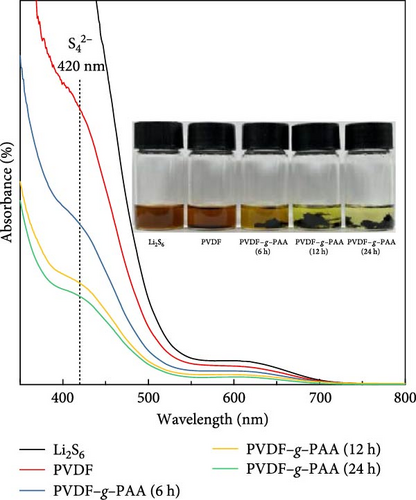
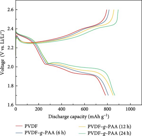
Figure 4 shows the results of an electrochemical analysis conducted to ascertain the effect of the LiPS adsorption ability on the cell performance using PVDF–g–PAA as a binder. The first galvanostatic charge/discharge profiles of the cathodes at 0.1 and 0.3C of the cathodes are presented in Figures S5 and 4a, respectively. The sulfur present in the S/C cathode underwent a multistage reaction during discharge process, with plateaus and slopes observed in the upper and lower voltage regions. This indicates sulfur conversion into high-order LiPS (Li2Sn, 4 ≤ n ≤ 8) and further reduction to the low-order LiPS (Li2Sn, 1 ≤ n ≤ 4) [23]. Regardless of the C-rate, when comparing the discharge profiles of the cells containing each binder, the polarization decreased in both regions with longer PAA-grafting times, thereby improving the total discharge capacity. The first discharge capacity at 0.3C increased in the following order: PVDF (790.6 mAh g−1)<PVDF–g–PAA (6 h, 817.2 mAh g−1)<PVDF–g–PAA (12 h, 849.9 mAh g−1)<PVDF–g–PAA (24 h, 865.0 mAh g−1). The cell with PVDF–g–PAA (24 h) exhibited the best performance, with the lowest polarization and highest discharge capacity. In Figure S6, the discharge capacity value (Qupper) in the upper region improved in the following order: PVDF (257.5 mAh g−1)<PVDF–g–PAA (6 h, 272.5 mAh g−1)<PVDF–g–PAA (12 h, 279.9 mAh g−1)<PVDF–g–PAA (24 h, 284.7 mAh g−1). This implies that the reduction of S8 to Li2S4 increased. Additionally, the values (Qlower) in the lower region increased in the same order. This implies a more efficient conversion of long-chain polysulfides to short-chain Li2S2/Li2S with an increase in the PAA ratio on the binder [50].
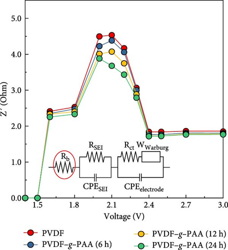
The bulk resistance (Rb) of the cells was measured using EIS for verifying the LiPS adsorption ability of each binder on the high sulfur loading electrode, as shown in Figure 4b. There was no significant difference in Rb in the voltage range of 3.0–2.4 V. In contrast, a significant increase in Rb was observed in the voltage range of 2.3–1.8 V because of the dissolution of LiPS in the electrolyte. When comparing the cells containing different PAA-grafting binders, the Rb decreased significantly with increasing PAA-grafting time within the voltage range of 2.3–1.8 V, which means a reduction in the concentration of LiPS in the electrolyte [51]. This result demonstrates that the high LiPS adsorption ability of PVDF–g–PAA alleviates the external diffusion of LiPS from the cathode and maintains more active sulfur species, which increases capacity with reduced shuttle effect.
Meanwhile, the affinity between the electrode and the electrolyte is also an important factor affecting the electrochemical performance. Contact angle measurements of the cathodes and EIS analysis before cycling were performed to determine the affinity between electrode and electrolyte, as shown in Figure S7a,b. The electrode containing PVDF–g–PAA showed a lower contact angle than that of PVDF indicating better affinity with the electrolyte. In Figure S7b, a series of PVDF–g–PAA showed reduced charge transfer resistance (Rct) with increasing grafting times. These findings prove that a series of PVDF–g–PAA enhanced the affinity between the electrode and electrolyte, which reduced the Rct. Consequently, high LiPS adsorption ability of PVDF–g–PAA as well as its affinity with the electrolyte could assist in improving the initial electrochemical performance, as shown in Figure S5.
The long-term stability of the cells with each synthesized binder and electrochemical analysis after 100 cycles are shown in Figure 5. The values of the discharge capacity and efficiency during 100 cycles at a current density of 0.3C are shown in Figure 5a, which compares the cycle stability of the cells. The values of the initial capacity increased from 790.6, 817.2, 849.9, and 865.0 mAh g−1 with an increased ratio of PAA, as shown in Figure 4a. After 100 cycles, the cathode using PVDF–g–PAA (12 h) exhibited better cycling performance with a capacity value of 644.1 mAh g−1 and capacity retention of 75.8% compared to that of the cathodes using PVDF (369.1 mAh g−1, 46.7%) and PVDF–g–PAA (6 h) (513.9 mAh g−1, 62.9%). When comparing the average coulombic efficiency of the cell for 100 cycles, the cathode with PVDF–g–PAA (12 h) showed the highest efficiency value (99.6%) compared to PVDF (96.7%) and PVDF–g–PAA (6 h) (98.7%), which showed the same trend as the capacity value and retention. When compared with other binders, PVDF–g–PAA (12 h) displays a satisfactory cycling performance with high sulfur loading and high current density, as shown in Table S3 and Figure S8.
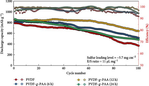
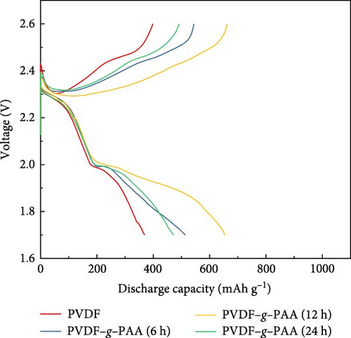
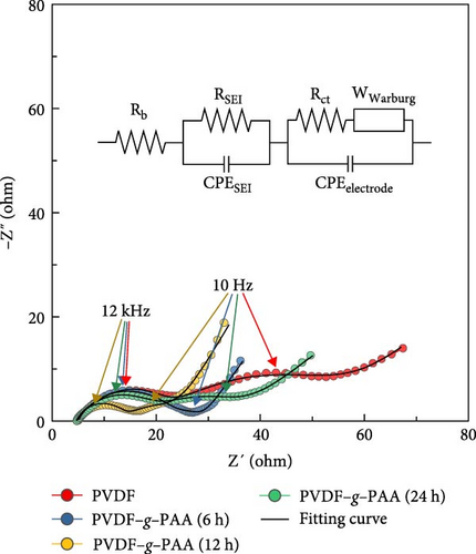
The cathode using PVDF–g–PAA (24 h) had the highest initial capacity value. However, after cycling, it showed a sharp capacity degradation, with the capacity value of 481.7 mAh g−1, relatively low average coulombic efficiency of 97.7%, and a poor retention of 55.7%. The voltage profiles of the 100th cycle were compared to investigate the cause of this phenomenon, as shown in Figure 5b. The polarization increased in the following order: PVDF–g–PAA (12 h)<PVDF–g–PAA (6 h)<PVDF–g–PAA (24 h)<PVDF. The slopes of the cells using PVDF–g–PAA (6 and 24 h) in the lower region became steep, similar to that of PVDF, resulting in severe polarization and lower capacity values. In contrast, the cell with PVDF–g–PAA (12 h) exhibited the lowest polarization with a gentle slope. For the cathode containing PVDF–g–PAA (24 h), the strong LiPS adsorption ability enabled effective sulfur utilization in the initial cell performance. However, it indicates severe polarization and rapid cell degradation during long-term cycling. This suggests that other factors could affect cycle stability besides the LiPS adsorption ability. Therefore, the overall resistance of the cells after 100 cycles was analyzed by EIS to determine factors affecting cycle stability, as shown in Figure 5c. The overall resistance of the cells containing different binders increased in the following order: PVDF–g–PAA (12 h)<PVDF–g–PAA (6 h)<PVDF–g–PAA (24 h)<PVDF. This trend was similar to that in Figures 5a,b, confirming that the significant increase in the total resistance was responsible for severe polarization, resulting in the deterioration of the cycle stability of PVDF–g–PAA (24 h).
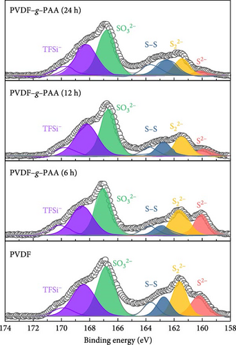
The cells operated for 100 cycles were disassembled and analyzed using XPS to examine factors that increased the overall cell resistance (Figure 6 and Figure S9). As shown in Figure 6, this allowed us to determine the surface composition of the Li metal anodes and the amount of LiPS deposited on the surface because of the LiPS shuttle effect over 100 cycles. The high-resolution S2p spectra of each anode with a series of PVDF–g–PAA binders showed lower peak intensities at 160 eV (Li2S) and 162 eV (Li2S2), which represent lithium sulfide species, than those of PVDF [52, 53]. The decrease in the intensities of the two peaks with longer grafting times suggests a reduction in the amount of Li2S2/Li2S present on the anode surface. The introduction of PVDF–g–PAA (24 h) resulted in a lower amount of Li2S2/Li2S deposition on the anode surface, even after cycling [49].
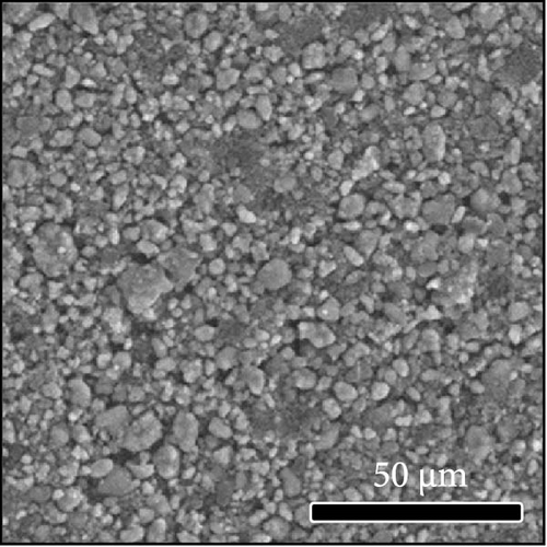
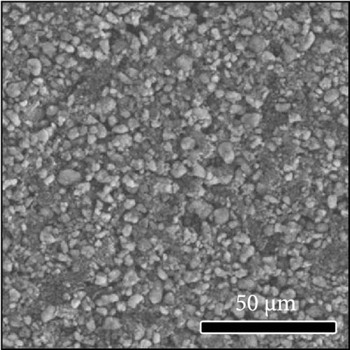
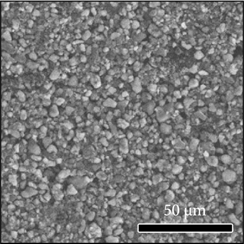
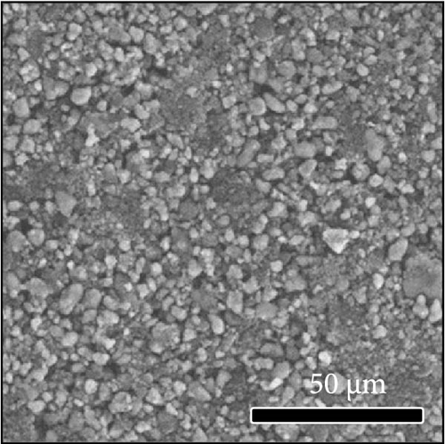
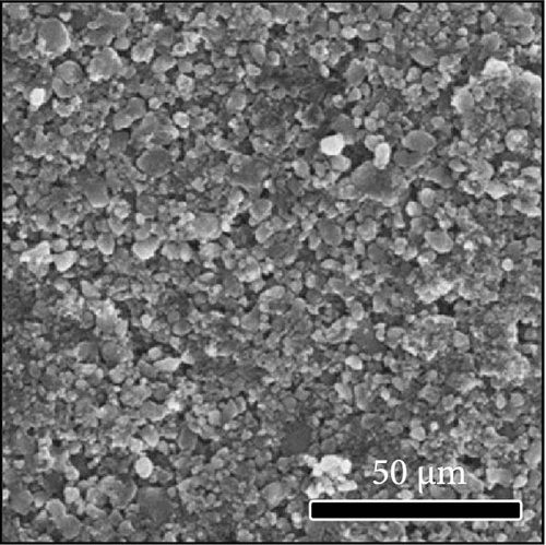
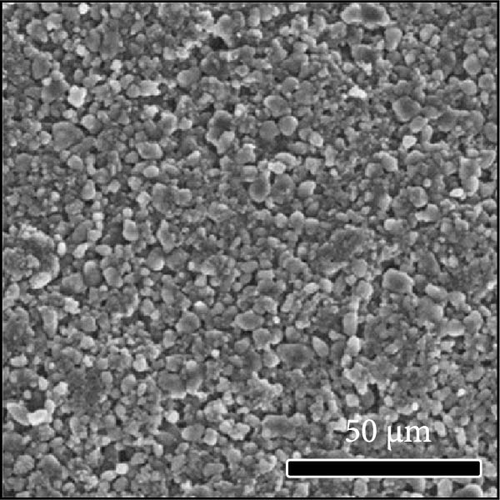
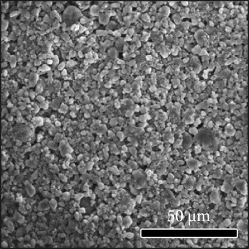
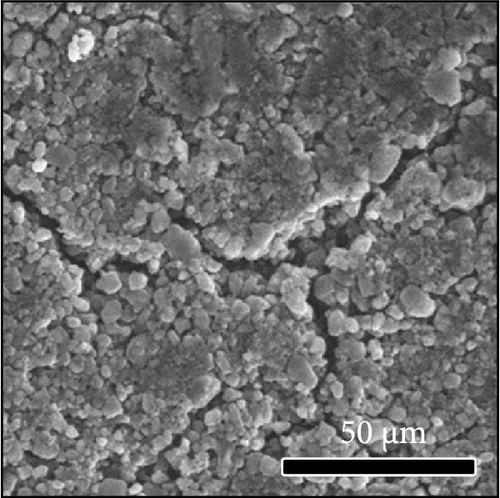
The morphologies of the cathodes before and after cycling were compared in Figure 7. There was no significant difference between the cathodes before cycling, regardless of the applied binder, as shown in Figure 7a−d. After 100 cycles, the structure of the cathodes using PVDF and PVDF–g–PAA (6 and 12 h) maintained similar characteristics to those before cycling, as shown in Figure 7e−g. However, the use of PVDF–g–PAA (24 h) resulted in a significant cracking of the cathode after cycling in Figure 7h [54]. This phenomenon was caused by the poor control of the volume change of the cathode by PVDF–g–PAA (24 h), which can be related to its mechanical properties.
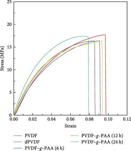
Tensile testing was conducted to measure the stress and strain values for investigating the effect of the mechanical properties of PVDF–g–PAA on the electrode degradation. As shown in Figure 8 and Table 2, the stress value (16.3 MPa) after PAA-grafting for up to 12 h was almost equivalent to that of dPVDF, whereas the strain value exhibited an increase from 0.085 to 0.093. The enhancement in elasticity can be attributed to the introduction of side chains, which remove the rigid traits of C═C bonds and change the structure from linear to branched, increasing the ratio of the amorphous phase [55, 56]. In the case of PVDF–g–PAA (24 h), a higher strength (stress value of 17.8 MPa) and lower elasticity (strain value of 0.077) were obtained compared to the other PAA-grafted binders. This may be attributed to the stiffness of the PAA moieties that affect the mechanical properties of the synthesized binder, leading to an increase in the overall resistance of the unit cell and rapid capacity fading during prolonged cycling [57, 58]. Consequently, PVDF–g–PAA (12 h) was an optimal binder structure that improves the cell performance because of its high LiPS adsorption ability while retaining its mechanical properties.
| Stress (MPa) | Strain (×10−2) | |
|---|---|---|
| PVDF | 17.7 | 9.7 |
| dPVDF | 16.3 | 8.5 |
| PVDF–g–PAA (6 h) | 16.3 | 9.2 |
| PVDF–g–PAA (12 h) | 16.4 | 9.3 |
| PVDF–g–PAA (24 h) | 17.8 | 7.7 |
- Abbreviations: dPVDF, dehydrofluorinated PVDF; PVDF, poly (vinylidene fluoride).
4. Conclusions
This study focused on the modification of a commercial PVDF binder by grafting PAA onto PVDF (PVDF–g–PAA) for an S/C cathode. PVDF–g–PAA was synthesized via a two-step process, wherein reactive C═C bonds were formed on the PVDF binder, and PAA was grafted sequentially. The synthesis conditions were evaluated based on the mechanical properties, LiPS adsorption ability, and electrochemical performance. The introduction of PAA into PVDF was effective for LiPS adsorption because of the strong LiPS adsorption ability of the carboxyl groups, and the LiPS adsorption capacity improved with the amount of PAA attached. Optical and electrochemical analyses revealed that the higher the content of grafted PAA, the more effective the suppression of the LiPS shuttling. However, in terms of the mechanical properties of binders, when the grafted PAA content exceeded a certain amount the elasticity was adversely affected, which resulted in a difficulty maintaining the structure of the electrode during long-term cycling. Considering these factors, an optimal structure of PVDF–g–PAA was developed while maintaining high LiPS adsorption and mechanical properties. Consequently, long-term cycling performance was achieved using a high sulfur loading cathode with the proposed optimal PVDF–g–PAA binder. This study highlights an approach to enhance the performance of high sulfur loading Li–S batteries with a small amount of binder and affirms the effect of binders on the cycling performance by optimizing the synthesis conditions. This series of experiments is expected to improve the performance of Li–S batteries by modifying the commercial PVDF binder and contribute to commercialization.
Conflicts of Interest
The authors declare no conflicts of interest.
Author Contributions
So-Young Nam: conceptualization, investigation, and writing–original draft. Hong Suk Kang: investigation and writing–review. Hyun-Seung Kim: supervision and writing–review and editing. Sang-Gil Woo: supervision and writing–review and editing. Je-Nam Lee: administration, supervision, and writing–review and editing.
Funding
This research was supported by the Nano-Material Technology Development Program through the National Research Foundation of Korea (NRF) funded by the Ministry of Science and ICT (Grant No. RS-2024–00455177). We acknowledge financial support from a National Research Foundation of Korea grant (NRF-2021M3H4A3A02086213).
Acknowledgments
This research was supported by the Nano-Material Technology Development Program through the National Research Foundation of Korea (NRF) funded by the Ministry of Science and ICT (Grant No. RS-2024–00455177). We acknowledge financial support from a National Research Foundation of Korea grant (NRF-2021M3H4A3A02086213).
Supporting Information
Additional supporting information can be found online in the Supporting Information section.
Open Research
Data Availability Statement
The data that support the findings of this study are included within the article and the Supporting Information and are also available from the corresponding author upon reasonable request.


