Performance Enhancement of Hybrid Energy Storage System for Electric Vehicle Using Intelligent-Based Controller
Abstract
Electric vehicles (EVs) are becoming increasingly popular, but their widespread adoption is still limited by issues such as short battery life and limited driving range. To address these challenges, this study proposes an intelligent current management strategy using a battery/supercapacitor hybrid energy storage system (HESS). The goal is to optimize current distribution, extend battery life, and improve overall energy efficiency. An algorithm is developed and tested using a hardware-in-the-loop (HIL) emulation platform. Two intelligent controllers—based on artificial neural networks (ANN) and adaptive neuro-fuzzy inference systems (ANFIS)—are designed and compared with a conventional rule-based controller and an EV system without a supercapacitor (SC). The ANN and ANFIS controllers are trained using data from the rule-based controller. The results show that the intelligent controllers, especially the ANFIS-based controller, significantly improve battery capacity reduction and energy management. In the Federal Test Procedure 75 (FTP-75) driving cycle, the ANFIS controller improved battery capacity by 13.27% at the 5000th cycle. In the European Driving Cycle (ECE-15) cycle, the improvement was 3.05%. For the Extra-Urban Driving Cycle (EUDC) cycle, the EV without a SC experienced 100% battery capacity loss by the 2000th cycle, while the ANFIS controller reduced this loss to 62.06% at the 5000th cycle. These findings confirm that the proposed ANFIS-based controller is the most effective in preserving battery life and enhancing driving range. This approach offers a practical and efficient solution to key limitations in EV performance, contributing to the development of more reliable and longer-lasting EVs.
1. Introduction
The growing concern over greenhouse gas emissions and air pollution from the transportation sector has spurred efforts to develop energy-efficient and environmental friendly vehicles [1]. In this context, electric vehicles (EVs) have emerged as a promising solution to reduce pollution and promote sustainability [2]. One of the key advantages of EVs lies in their regenerative braking technology, which enables them to convert kinetic energy into electrical energy during braking [3]. This recovered energy can be stored in the vehicle’s battery, making regenerative braking an efficient way to extend the battery’s charge and discharge cycle and improve overall energy utilization. This feature is particularly beneficial in urban areas with heavy traffic or hilly terrains [4].
To further enhance EV performance and increase battery life, researchers have explored the concept of hybrid energy storage systems (HESSs) [5]. By combining traditional batteries with supercapacitors (SCs), HESS can overcome the limitations of conventional batteries [6]. Additionally, EV batteries can be utilized for vehicle-to-grid (V2G) applications [7], enabling bidirectional energy transfers between EVs and the power grid. Effective energy management controllers are vital for scheduling these energy transfers and optimizing overall system performance.
The literature explores various control strategies for optimizing HESS performance, including dynamic programing (DP) [8], rule-based control, and model predictive control (MPC) [8, 9]. These strategies aim to achieve specific objectives, such as maximizing battery life, minimizing energy cycles for driving, and ensuring cost-effectiveness.
To find the global optimal solution, some researchers have applied optimization-based methods like linear programing (LP) and DP. However, these techniques require prior knowledge of the entire drive cycle and load demand profile, making them unsuitable for real time or online solutions [10]. While DP can serve as a benchmark for comparing the performance of other strategies, it lacks the capability of providing instantaneous responses for dynamic energy management.
An alternative online implementation strategy is MPC, where the optimization problem is formulated over a prediction horizon [11]. MPC can adjust its decisions based on real-time measurements and predictions, allowing for dynamic adaptation to changing driving conditions. However, for complex systems, MPC may entail heavy computational requirements, potentially impacting the energy management system’s response time. Dusmez and Khaligh [12] propose an intelligent energy management strategy for a battery/SC HESS in EVs. The study utilizes a fuzzy logic-based controller to dynamically allocate power between the battery and SC based on real-time driving conditions and load demands [13]. The fuzzy logic controller effectively optimizes energy usage, enhances battery life, and extends the driving range of EVs [14].
This article proposes ANFIS controller for HESS, which combines the advantages of neural networks and fuzzy logic to optimize the power distribution between the battery and SC. The controller adapts to varying driving conditions and load demands, ensuring efficient utilization of energy and enhancing battery life. Simulation results demonstrate the effectiveness of the proposed controller in achieving better energy efficiency and extended driving range compared to traditional control methods. The ANFIS controller is trained using rule-based controller to make it an effective online energy management system. The evaluation includes a comparison with NN-based controller and rule-based controller. Battery/SC HESS is tested using the Federal Test Procedure 75 (FTP-75) driving cycle which is used to simulate typical urban driving conditions in the United States. To show dynamic profile of the system, results are verified for European Driving Cycle (ECE-15) and Extra-Urban Driving Cycle (EUDC).
The research gap lies in the need for a real time, adaptive energy management strategy that optimally distributes power between the battery and SC while addressing the limitations of conventional energy management techniques such as DP and MPC, which are computationally intensive and unsuitable for real-time applications. The selected driving cycles—FTP-75, ECE-15, and EUDC—are chosen to evaluate the controller’s performance under diverse urban and extra-urban driving conditions, ensuring its adaptability to real-world scenarios. The novelty of this work lies in the development of an ANFIS-based controller trained using rule-based logic, enabling intelligent power distribution between the battery and SC. This approach reduces peak battery current, minimizes energy losses, extends battery life, and enhances EV efficiency compared to conventional rule-based and ANN-based controllers.
2. System Modeling
System modeling includes EV powertrain, HESS, and different controllers used for power sharing between battery and SC.
2.1. Electric Vehicle Powertrain
The powertrain control module (PCM) [15] uses a field-oriented control (FOC) system [16] with regenerative braking to manage the vehicle’s powertrain efficiently. The PCM employs FOC with PI regulators for current control, ensuring optimal machine flux and torque. An indirect FOC method calculates the rotor flux angle. The flux weakening method enables the rotor to exceed the base speed. Refer Table 1 for specification of the three-phase inverter.
| 3-Phase inverter parameters | Value |
|---|---|
| Nominal power | 175 kVA |
| Nominal voltage | 240 V |
| Nominal DC link voltage | 400 V |
The induction motor is loaded with variable torque. The specifications of motor are mentioned in Table 2.
| Type | Squirrel-cage induction motor |
|---|---|
| Nominal voltage | 400 V |
| Maximum power | 270 kW |
| Maximum RPM | 16,950 |
| Number of poles | 4 |
2.2. Modeling of Hybrid Energy Storage System
The HESS considered in this study consists of two main components: the battery and the SC. The equivalent circuit model of the energy storage devices is depicted in Figure 1. The open-circuit voltage Vb, oc represents the voltage of the battery when no load is connected, and Vsc, oc denotes the voltage of SC under the same condition.
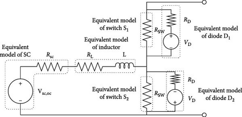
In this study, the open circuit voltage of Battery Vb, oc is assumed to remain constant throughout a single drive cycle. This assumption is based on the characteristics of the LiFePO4 battery used, which exhibits a flat discharge curve within the usable discharge range of 90% state of charge (SoC) to 30% SoC.
The energy storage system comprises a series-connected pack of high-capacity NCR18650B battery cells sourced from Panasonic, providing a total energy storage capacity of 102 kWh. The pack also includes 92 BCAP 3400 SCs and has a weight of 47 kg, while the battery pack alone weighs 430 kg. The SC pack has an energy storage capacity of 335 Wh. The battery pack with a capacity of 102 kWh occupies a volume of 150 L, while the SC pack occupies a volume of 50 L [17].
The estimated weight of the DC–DC converter is 30 kg. Considering a packing factor of 1.4, the total mass and volume of the battery-SC HESS are 668 kg and 280 L, respectively. For detailed specifications of the battery and SC cells, please refer to Table 3.
| Specifications | Battery | Supercapacitor |
|---|---|---|
| Nominal voltage (V) | 3.6 | 2.7 |
| Nominal capacity (Ah) | 3.25 | N/A |
| Rated capacitance (F) | N/A | 3400 |
| Weight (kg) | 0.0485 | 0.513 |
The SC connects to the system through a bidirectional DC–DC converter, enabling energy transfer between the SC and the EV. The converter operates in boost mode, supplying energy from the SC to the EV (Figure 2a,b), and in buck mode during regenerative braking, transferring energy from the EV to the SC Figure 2c,d. A rule-based controller triggers the Buck-boost converter.
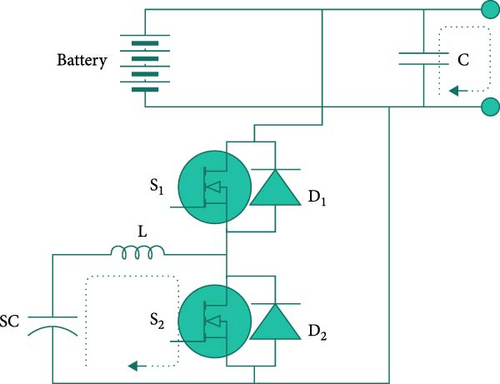
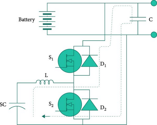
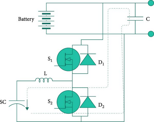
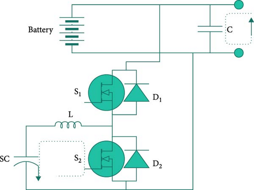
Figure 2 shows the equivalent circuit model of the Buck-Boost converter with inductor represented by L and winding resistance by RL. The MOSFET component is modeled with on-resistance RSW, and the behavior of the body diode is represented using resistance RD and voltage source VD. The state-space average model considers circuit parasitics, resulting in duty cycles DBoost and DBuck between 0 and 1 for the converter in boost and buck modes, respectively [20]. Table 4 provides the DC–DC Buck-Boost converter specifications.
| Parameter | Symbol | Value | Parameter | Symbol | Value |
|---|---|---|---|---|---|
| Inductor | L | 0.023 H | Inductor wing resistance | RL | 10 mΏ |
| D. C. link capacitor | C | 0.0215 F | Switch on resistance | RSW | 43 mΏ |
| Carrier frequency | F | 20,000 Hz | Body diode resistance | RD | 40 mΏ |
| Input voltage | Vin | 200 V | MOSFET rise-time | tr | 13 ns |
| Output voltage | Vout | 400 V | MOSFET fall-time | tf | 12 ns |
| MOSFET output capacitance | Coss | 1860 pF | Reverse Recovery charge | Qrr | 2 µC |
3. Controller Design for Energy Management
3.1. Rule-Based Controller
A rule-based controller operates on predefined rules and if-then statements to make decisions and control system behavior. It evaluates input variables against these rules to determine actions. While rule-based controllers are transparent and interpretable, they may struggle with complex and dynamic systems.
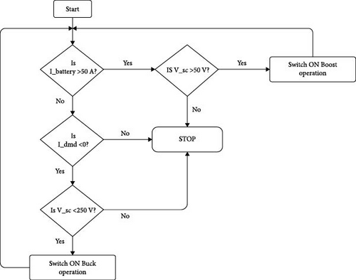
The flowchart in Figure 3 illustrates the rule-based control algorithm for the hybrid power system where I_battery is battery current, V_sc is SC voltage, and I_dmd is demand current of induction motor. It determines the power split between the battery and SC based on current requests and SC voltage. The controller ensures proper power supply to the EV’s motor depending on current conditions.
3.2. Artificial Neural Network-Based Controller
In this study, an artificial neural network (ANN) is used which is a powerful and versatile machine learning model inspired by the structure and function of the human brain. ANN consist of interconnected nodes (neurons) organized into layers. Each neuron receives input, processes it in hidden layer, and produces an output [21]. Through the training process, neural networks learn to make predictions and perform tasks based on the patterns and relationships within the training data.
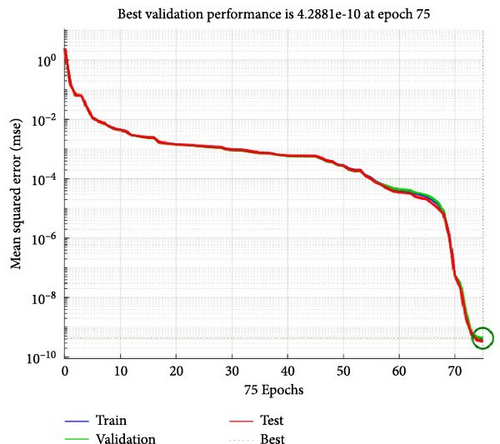
For this study, the ANN was trained using a substantial dataset consisting of 700,000 samples of input–output pairs. This large training dataset allowed the neural network to learn complex patterns and generalize well to unseen data, enhancing its predictive capabilities. Figure 4 shows the results obtained during the training and validation of the ANN-based controller.


During training, the gradient value was monitored, which measures the slope of the error curve concerning the network’s parameters. Figure 4a indicates gradient of 6.0827e-8 which indicates that the network was fine-tuning its parameters with precision, approaching the optimal values for better performance.
To prevent overshooting during the training process, learning rate denoted as Mu of 1e-12 was used, as shown in Figure 4b. The small learning rate ensures that the network’s weight updates are incremental and steady, enabling stable convergence during training.
In Figure 4c, validation fail is zero for all epochs. The validation fail represents how well the model fits new data. As the training progresses, the error decreases, indicating that the neural network is getting better at approximating the desired output as shown in Figure 4d. During validation, the performance of the network was evaluated using the mean squared error (MSE) metric, with a value of 5.4106e-12. A low MSE indicates that the network’s predictions are close to the validation target values, confirming its accuracy on data. The dotted vertical line represents the epoch at which the best validation performance was achieved. The dotted horizontal line may indicate the minimum validation error.
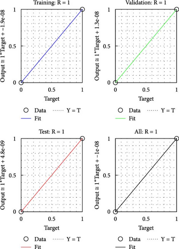
The training and validation R values both indicate 1, as depicted in Figure 4e, The neural network achieved a perfect correlation between its predictions and the actual target values for both the training and validation datasets. This high correlation reflects the network’s ability to capture underlying patterns effectively and generalize well to new data. At the 75th epoch, the R value for the test dataset was 0.99992, which is extremely close to 1. A value close to 1 suggests that the network’s predictions on the test dataset are highly accurate, with only a negligible difference from the true target values. A dotted line “Y = T” indicates the reference line where the output exactly matches the target.
Overall, our study demonstrates the effectiveness and strong performance of the neural network, showcasing its potential for making accurate predictions and solving complex tasks in various real-world applications.
3.3. ANFIS-Based Controller
The ANFIS controller is a powerful intelligent control logic that combines the strengths of ANNs and fuzzy logic, making it suitable for handling complex and dynamic control tasks.
ANFIS architecture consists of five layers with output is depicted by Oi,l where i is the node of l layer [22].
During the experimentation and evaluation phase, promising results are obtained as evidenced by the performance metrics of the ANFIS controller. The root mean square error (RMSE) value, which measures the accuracy of the controller’s output in relation to the desired output, was found to be 0.114729. This indicates that the ANFIS controller is capable of generating highly accurate control actions for the given system, ensuring improved efficiency and optimal energy utilization. Furthermore, the ANFIS controller exhibited a notable number of nodes, amounting to 91. The higher number of nodes in the ANFIS network indicates the complexity and adaptability of the controller, allowing it to handle intricate control tasks and effectively map inputs to desired outputs.
The proposed MATLAB/Simulink model of ANFIS-based power sharing between HESS controller is depicted in Figure 5a for boost operation and Figure 6a for buck operation. Battery current, SC voltage, and power demand are taken as the input training data set for the ANFIS. The ANFIS reference model gives out the crisp value of duty cycle. For boost operation, consider three inputs (battery current, SC voltage, and power demand) and for buck, inputs are 2 (SC voltage and power demand). To show relation between inputs and outputs, surface plots are drawn. For boost operation refer Figure 5b,c and for buck operation refer Figure 6b.
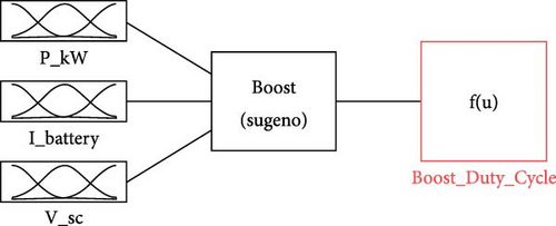
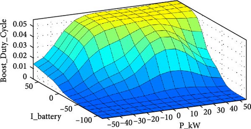
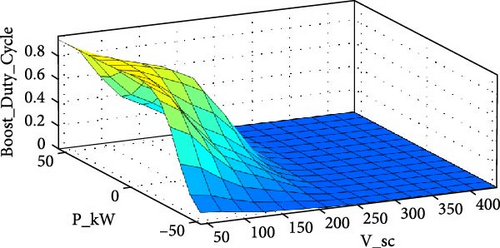
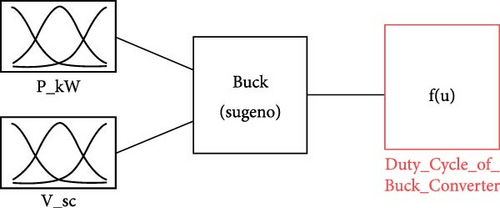

In addition, the ANFIS controller was governed by 91 fuzzy rules for boost operation and 30 for buck operation, which played a crucial role in defining the system’s behavior and generating appropriate control actions based on the linguistic descriptions of the input–output relationships. These fuzzy rules were determined during the training process, ensuring the ANFIS controller could effectively adapt to various scenarios and system conditions. For the training phase, utilized same data used to train ANN-based controller. This extensive training data allowed the ANFIS controller to learn and generalize well, enabling it to make accurate decisions even in the face of diverse and real-world operating conditions. The training process consisted of 100 epochs, during which the entire dataset was iteratively presented to the ANFIS controller. The numerous epochs allowed the controller’s parameters to be fine-tuned, leading to improved performance and enhanced control capabilities.
The impressive results obtained from this study highlight the potential and effectiveness of the ANFIS controller for optimizing the HESS in EVs. By providing this comprehensive data in article, we demonstrate the robustness and accuracy of the ANFIS-based control approach, paving the way for further research and implementation in real-world EV applications.
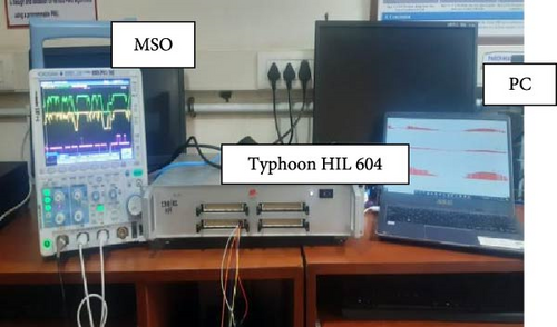
Figure 7 shows the Typhoon HIL604 hardware-in-the-loop (HIL) simulation system, offering a virtual vehicle environment for validating the proposed controller and testing the system performance. HIL systems allow testing controller behavior under various conditions, facilitating early detection and resolution of potential issues during development. The Typhoon HIL604 provides real-time emulation and precise testing of controllers with extensive interface options for signal modification and analysis.
4. Results
Figure 8 illustrates the SoC profiles for different controller configurations in the context of an EV undergoing the FTP-75 urban driving cycle, spanning 2475 s, which encompasses both acceleration and deceleration phases. The initial SoC is set at 80%. Analysis of the graph reveals that in the absence of regenerative braking, the battery’s SoC experiences a decline to 77.3%. In contrast, when regenerative braking capability is applied, the SoC reduction is mitigated to 78.4%. This observation highlights that the utilization of regenerative braking contributes to an enhancement in driving range.
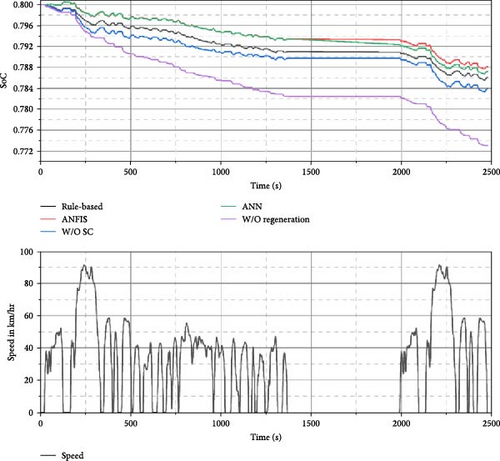
The diagram also portrays the influence of SC strategies on battery SoC. Employing a rule-based controller for both the battery and SC yields a SoC reduction to 78.6%, affording benefits in terms of extended driving range and amelioration in battery longevity due to the attenuation of peak current levels. The implementation of an ANN-based controller results in a slight reduction in battery SoC from 80% to 78.7% over a 2475-second driving cycle. While this variation may appear minimal, it holds significance for long-distance travel where energy efficiency is critical. In comparison, adopting an ANFIS-based controller yields a SoC decrease to 78.8%, markedly enhancing driving range and battery life compared to the rule-based and ANN-based counterparts. Remarkably, the ANFIS controller surpasses both the no-regeneration EV and the regenerative EV in terms of performance. This shows that maintaining SoC of the battery, the driving range of the EV can be improved; this is one of the concerns of this paper.
The graph further elucidates the SoC dynamics concerning vehicle speed. During speed acceleration instances, the battery’s SoC experiences a swift depletion in the absence of regenerative braking, unlike the regenerative and SC-assisted cases, where the reduction is less pronounced. During deceleration phases, the SoC of the battery witnesses increments in scenarios involving regenerative braking and SC, while it remains relatively steady without regenerative braking. To show dynamic profile of the system, SoC is verified for European driving cycle (ECE-15) and extra-urban driving cycle (EUDC) as shown in Table 5. The performance of ANFIS-based controller for ECE-15 and EUDC driving cycle is better compared to rule-based controller and ANN-based controller.
| HESS based on | SoC after driving cycle (%) | ||
|---|---|---|---|
| FTP-75 | ECE-15 | EUDC | |
| Without regeneration | 77.3 | 79.87 | 79.05 |
| Without SC | 78.4 | 79.93 | 79.16 |
| Rule-based controller | 78.6 | 79.953 | 79.58 |
| ANN-based controller | 78.7 | 79.94 | 79.579 |
| ANFIS-based controller | 78.8 | 79.96 | 79.65 |
Figure 9 illustrates the battery current over a 125-s interval to ensure optimal visualization. Extending the plot to cover the full 2475-s cycle would lead to visual compression, impeding clarity. Battery current exhibits fluctuations corresponding to alterations in vehicle speed for 125 s.
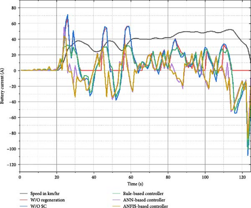
Figure 9 reveals a pattern wherein positive battery current during acceleration signifies power transfer from the battery to the motor. Conversely, negative current during deceleration denotes the operation of regenerative braking, wherein power flows from the motor back to the battery. The integration of rule-based, ANN, and ANFIS controllers in a HESS resulted in notable reductions in both average and peak current compared to a system without a controller. In terms of average current, for the FTP-75 cycle, the rule-based controller reduces the average current by 13.75%, while the ANN-based and ANFIS-based controllers achieve even greater reductions, with 20.48% and 21.22% reductions, respectively. This highlights that ANN and ANFIS controllers are more effective at minimizing current consumption compared to the rule-based controller. For the ECE-15 cycle, the rule-based controller offers a modest reduction, but the ANN-based controller performs worse than the rule-based method. On the other hand, the ANFIS-based controller shows the best performance, reducing the average current by 24.3%. The EUDC cycle, which tends to have higher average current demands, also sees the best results from the ANFIS-based controller, with a 48.5% reduction in average current, followed by the rule-based and ANN-based controllers with reductions of 31.1% and 32.1%, respectively. These results suggest that ANFIS adapts more effectively to the complexities of different driving cycles, especially when the demand for current is high.
When considering peak current, the reductions are more pronounced. For FTP-75, the rule-based controller reduces peak current by 53%, while the ANN and ANFIS controllers achieve even greater reductions, with 56.44% and 57.58% reductions, respectively. This demonstrates that the ANN and ANFIS controllers are particularly efficient in limiting peak current during high-demand scenarios. For the ECE-15 cycle, the rule-based controller reduces peak current by 24.8%, whereas the ANN-based controller slightly increases the peak current compared to the rule-based method. In contrast, the ANFIS-based controller outperforms the others, reducing peak current by 39.2%. Finally, for the EUDC cycle, the rule-based controller reduces peak current by 40.2%, while the ANN and ANFIS controllers achieve reductions of 44.1% and 45.4%, respectively, with ANFIS again leading the performance. These results further confirm that the ANFIS-based controller is most effective in managing peak current, particularly during demanding driving conditions as shown in Table 6. The average current increases in case of ANN-based controller compared to rule-based controller and decreases in ANFIS-based controller which shows that the performance of ANFIS-based controller remain stable for different driving cycle. In case EUDC driving cycle, ANFIS-based controller shows better results compared to other control strategy.
| HESS based on | Without SC | Rule-based | ANN-based | ANFIS-based |
|---|---|---|---|---|
| Average current (A) | ||||
| FTP-75 | 13.52 | 11.66 | 10.75 | 10.65 |
| ECE-15 | 7.756 | 6.9334 | 7.34 | 5.89 |
| EUDC | 26.73 | 18.43 | 18.18 | 13.69 |
| Peak current (A) | ||||
| FTP-75 | 200 | 93.83 | 87.12 | 84.83 |
| ECE-15 | 46.82 | 35.27 | 37.19 | 28.43 |
| EUDC | 106.70 | 63.658 | 59.65 | 58.36 |
Figure 10 depicts the power delivered by the battery under different conditions. Specifically, it illustrates the power consumption pattern as a function of changing vehicle speed. The power profile graph reflects positive values during acceleration (battery to motor transfer) and negative values during deceleration (regenerative braking). In scenarios without regeneration, deceleration power consumption remains at zero.
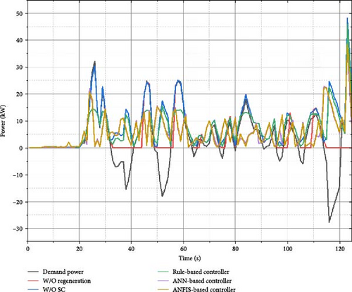
Furthermore, in the context of regenerative braking without the implementation of SC, the power flow is observed to shift from the motor to the battery during regenerative phases. In a HESS, employing different controllers, including rule-based, ANN, and ANFIS revealed varied power distribution dynamics.
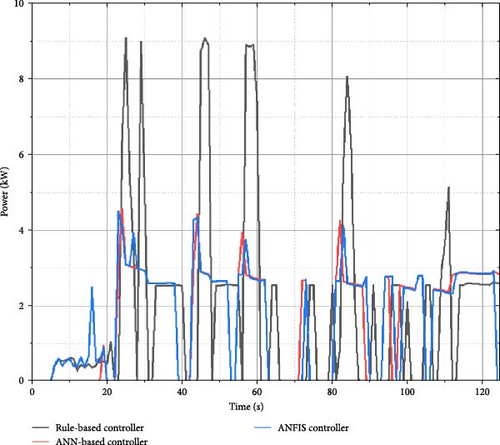
Figure 11 shows power delivered by SC. It shows that for rule-based controller, SC supplying 19.03% power whereas for intelligent-based controller, SC supplying 10.87%. Intelligent-based controller optimizes the power more precisely as compared to rule-based controller.
a = 1.226; λ = 0.2797; d = 9.263.
The pre-exponent parameter under different battery current profiles and current rates can be estimated dynamically based on Equation (6). Thus, the battery cycle life estimation model can be used under various current profiles
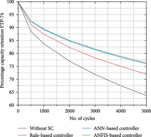
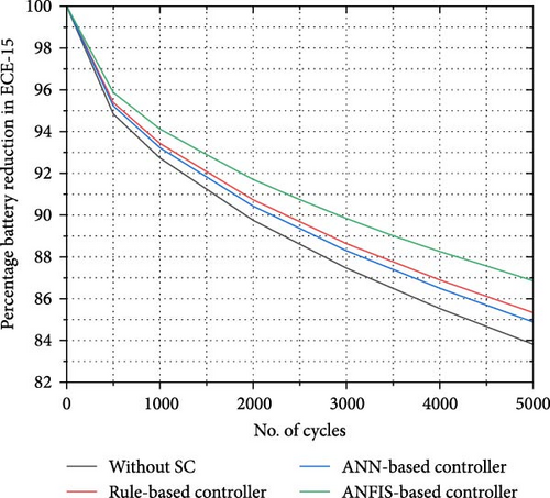
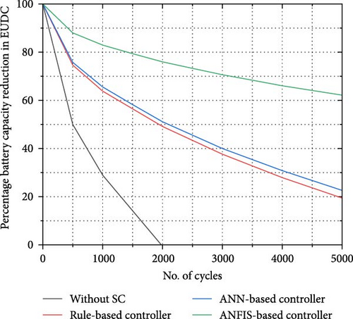
Utilizing different controllers in a system over a range of cycles (0 to 5000), the rule-based, ANN and ANFIS controllers consistently demonstrated reduced battery capacity reduction compared to the system without a SC as shown in Figure 12. Among them, the ANFIS-based controller exhibited the most efficient performance in preserving battery capacity across the entire cycle range as compared to rule-based controller and ANN-based controller, specifically the ANN and ANFIS controllers, exhibit superior performance in minimizing battery capacity reduction compared to the scenario without SC control. The ANFIS-based controller stands out as the most effective strategy among the ones evaluated across the specified FTP-75, ECE-15 and EUDC cycles. In case FTP-75 driving cycle, battery capacity increased up 13.27% at 5000th cycle, in ECE-15 driving cycle, increased to 3.05% and in case of EUDC driving cycle, 100% battery capacity reduced at 2000th driving cycle for without SC but in for ANFIS-based controller, battery capacity loss is 62.056% at 5000th driving cycle.
5. Conclusion
In conclusion, our study examined the dynamic interplay of various controller configurations on an EV HESS with different urban driving cycles such as FTP-75, ECE-15, and EUDC. Through a comprehensive analysis, significant insights into SoC profiles, battery current fluctuations, and power consumption patterns were studied.
Regenerative braking emerged as a pivotal factor, showcasing its potential to enhance driving range by mitigating SoC reduction. The integration of SC, particularly with rule-based strategies, demonstrated marked benefits in terms of extended driving range and battery longevity. ANFIS-based control, remarkable in its performance, yielded a substantial SoC improvement, surpassing both no-regeneration and regenerative EVs.
The article presents an in-depth investigation into enhancing EV battery performance through the implementation of an ANFIS-based controller for HESS. The study addresses critical challenges faced by EVs, such as declining battery life and limited operating range, proposing an optimal distribution of current within a battery/SC HESS to maximize battery life and extend driving range. Comparative evaluations against rule-based and neural network controllers reveal that the ANFIS-based controller significantly outperforms, demonstrating notable reductions in battery current, improved SoC dynamics, and efficient power distribution, showcasing its potential to address key EV challenges and contribute to the advancement of EV technology. To check dynamic performance of the system, experiment is performed on different driving cycles using hardware in loop system.
This research emphasizes the critical role of regenerative strategies and intelligent supervisory control in optimizing EV performance, driving range, and battery life. These findings provide valuable insights for advancing sustainable and efficient electric mobility systems.
Conflicts of Interest
The authors declare no conflicts of interest.
Funding
No funding was received for this manuscript.
Open Research
Data Availability Statement
The data that support the findings of this study are available from the corresponding author upon reasonable request.


