Numerical Analysis of the Thermal Performance of a Novel Dual-Purpose Solar Air-Water Heater
Abstract
Flat plate solar water heaters (SWHs) are well-known thermal systems for their simplicity and efficiency in heating water. Enhancing their functionality, dual-purpose solar air-water heaters (SAWHs) integrate both water and space heating, thereby reducing energy costs while maintaining minimal installation complexity. These systems harness solar energy to efficiently transfer heat to both air and water, presenting a versatile solution for sustainable energy applications. This research investigates the thermal performance of a new design of dual-purpose SAWH under solar irradiation of 1100 W/m. In this innovative design, the water tubes feature a semi-circular cross-section to maximize contact area with the absorber. The study examines the effect of varying inlet water temperatures (32, 37, and 42°C) on heat transfer, temperature distribution, and thermal efficiency. Additionally, the effects of different air mass flow rates have been investigated. Results indicate that as the inlet water temperature increases, the heat transfer rate on the waterside decreases from 788 to 695 W due to the reduced temperature difference between the water tubes and the absorber. Conversely, the air-side heat transfer rate increases from 120 to 157.6 W, benefiting from enhanced heat transfer facilitated by higher temperature difference. Thermal efficiency shows a slight decline, dropping from 82.5% to 77.5% with higher inlet water temperatures. The effect of air mass flow rates (0.01–0.026 kg/s) and water mass flow rates (0.015–0.06 kg/s) on thermal efficiency were investigated, showing a 1.77% improvement in efficiency for air and a 5.13% increase in water flow rates. These findings emphasize the advantages of dual-purpose solar air water heater systems, achieving an average thermal efficiency of about 80%, which is significantly higher than the 77.6% and 27.8% efficiency of a comparable single-purpose solar air heater (SAH) and solar water heart, respectively.
1. Introduction
As the population continues to grow, so does energy consumption. Since a significant portion of energy production still relies on the consumption of fossil fuels, which are the primary contributors to environmental hazardous such as COx and NOx emissions, the demand for clean and renewable energy sources has become increasingly urgent [1–3]. Solar energy is one of the most promising alternatives to fossil fuels, widely adopted today due to its abundant availability and minimal environmental impact. It offers a versatile range of applications, from providing thermal energy for heating water and air. With advancements in technology, solar energy systems have become more efficient and cost-effective, making them increasingly accessible for both residential and industrial use. Additionally, solar power contributes significantly to reducing greenhouse gas emissions, further enhancing its role in sustainable energy solutions [4–7].
A substantial amount of energy in buildings, including commercial centers, hospitals, residential areas, and some processes in industries, is consumed to produce hot water. Cao et al. [8] revealed that in buildings, ~60% of energy use is dedicated to space heating and cooling. Also, Treichel and Cruickshank [9] reported that conventional heating systems account for 62% of greenhouse gas emissions from water heating and 21% from space heating. Solar water heaters (SWHs), which harness solar thermal energy, can be employed to produce hot water or steam for different applications. Specifically, SWH offers a clean, reliable, and economical solution to utilize solar energy effectively, meeting 50%–80% of hot water demands. SWH systems can be successfully implemented in various geographical locations and climatic regions around the world; however, the heat generated by these systems primarily depends on the amount of solar radiation available in the specific region or location [10–13].
Flat plate SWHs are recognized as one of the most prevalent technologies in solar thermal water heating. Their widespread use is largely attributed to their straightforward design, which efficiently meets heat demand at low and medium temperatures, in addition to their user-friendly operation, low maintenance needs, and cost-effectiveness. Improving the thermal efficiency of SWH units is essential for the development of economically viable solar water heating systems. The efficiency of flat plate solar collectors (FPSCs) is low and often limited to around 60%, largely because of the inadequate thermophysical properties of the heat transfer fluid and considerable heat loss from the system. Also, a common issue that diminishes the performance of FPSC over time is the accumulation of dust, which necessitates regular cleaning to maintain optimal efficiency [14–16].
Recently, many researchers have focused on various methods to enhance the thermal performance of SWHs. Pandey and Chaurasiya [17] provide a comprehensive review of various strategies aimed at improving the efficiency of flat plate collectors (FPCs). It examines the impact of utilizing nanofluids as heat transfer fluids, modifying absorber plate designs to enhance radiation absorption, and implementing techniques to reduce heat loss. Additionally, it explores the use of polymers, mini channels for fluid flow, and phase change materials (PCMs) for nighttime heat delivery without storage tanks. The paper also discusses the effects of enhancement devices, such as inserts and reflectors, on performance. In the study by Zamzamian et al. [18], an experimental investigation was carried out to assess the impact of copper nanoparticles on the efficiency of an FPSC. The experiments were conducted using various volumetric flow rates of the nanofluid, ranging from 0.016 to 0.050 kg/s. The findings revealed that increasing the weight fraction of the nanoparticles, specifically at levels of 0.2% and 0.3% with an average diameter of 10 nm, resulted in improved efficiency of the collector.
Tong et al. [19] experimentally investigated the energy and exergy efficiencies of an FPSC utilizing water, Al2O3 nanofluid, and CuO nanofluid as working fluids. The results demonstrated that incorporating Al2O3 and CuO nanofluids significantly enhances the thermal efficiency compared to using water. Notably, the collector achieved its highest efficiency with Al2O3 nanofluid, which was 21.9% greater than that achieved with water. Additionally, the optimal exergy efficiency of the solar collector was observed with a 1.0 vol% concentration of Al2O3 nanofluid.
Zhou et al. [20] developed a 3D numerical model to analyze the performance of a flat-plate solar collector incorporating transparent insulation material (TIM). Their study explored the effects of TIM transmittance, fluid flow rate, and collector tilt angle. Results indicated that when the TIM transmittance dropped below 0.8, the collector’s efficiency was lower than that of a collector without TIM. Additionally, greater heat losses occurred at lower mass flow rates, and the tilt angle significantly impacted the collector’s performance, especially when TIM was used. Ammar et al. [21, 22] conducted studies focused on enhancing the design and efficiency of innovative facade solar collectors using TIM with parallel slats (TIM-PS). In the first study, a 3D numerical model was used to assess the thermal and efficiency performance of a solar air collector, analyzing factors such as slat quantity, height, material, and tilt angle. The optimal configuration achieved 81% thermal efficiency with a 45° tilt and six slats. The second study examined a FPC that operates through natural convection, incorporating perforated and inclined TIM-PS. The findings identified a cost-effective setup using seven slats inclined at +45°, which achieved about 60% thermal efficiency while remaining lightweight and economical.
Various researchers have explored different methods to enhance the efficiency of flat-plate solar collectors, including the use of PCMs and enhancement devices, such as fins, to increase the heat transfer area and absorber coating [23, 24]. Wang et al. [25] presented a novel dual-PCM FPC incorporating PCMs with different melting temperatures. Their study showed that the efficiency of the dual-PCM collector increased by 24.1% when the low-melting PCM was placed beneath the high-melting PCM and by 19.6% when the arrangement was reversed. Bharathiraja et al. [26] investigated an FPSC with hybrid nano-enhanced PCM, achieving improved thermal efficiency (71.7%), sustained hot water output (up to 70°C), and CFD validation with under 3.5% error. In a study by Zhou et al. [27], a PCM-enhanced FPCs was proposed to prevent freezing, demonstrating effective operation at daily average temperatures between 0 and 5°C, unlike conventional systems, which freeze below 5°C.
Wang et al. [28] investigated the effect of fin geometry in a square SWH using paraffin as PCM, showing that adding fins significantly reduced melting time—by up to 71% with three fins and 74% with a 5 cm fin height. In a study by Vengadesan et al. [29], rectangular tubes with continuous and discontinuous V-corrugated fins were introduced on the absorber surface of a solar air heater (SAH), achieving heat transfer coefficients of 79.2 and 67.5 W/m2 K, and energy efficiencies of 82.5% and 79%, respectively, while another study by the same author [30] proposed a novel flat surface receiver with staggered square cross-sectioned tubular fins, enhancing heat transfer and achieving peak thermal and exergy efficiencies of 71% and 8.11%, with a 46.2% reduction in the cost per kWh of useful energy compared to coal power plants.
Balaji et al. [31] experimentally showed that using copper rods and tubes as thermal enhancers in FPSCs improved performance, reducing key convection parameters and achieving evaluation factors of 1.38 and 1.29, respectively. In an experimental work, Kanimozhi et al. [32] examined a SWH featuring a porous medium made of pebble stones combined with an agitator to enhance the heat transfer area. The results revealed that the use of the porous medium improved thermal efficiency to 63.8%, in contrast to 56.6% without it.
A cost-effective and straightforward way to increase the thermal efficiency of a flat-plate solar collector is to use it as a dual-purpose device, where heat is simultaneously transferred to both air and water. The dual-purpose systems, known as solar air-water heaters (SAWHs), have been shown to effectively reduce energy costs related to water and space heating while requiring minimal installation efforts. These systems capture solar energy through the collector and transfer the absorbed heat to both air and water. The use of these two working fluids as heat transfer media allows for the concurrent heating of air for space heating and water for domestic or industrial applications. Studies have demonstrated that this combination enhances energy efficiency by optimizing the use of solar radiation throughout the day [33–35]. Only a limited number of studies have investigated the thermal performance of SAWHs, and most of these focus on experimental approaches rather than numerical modeling [36–39]. Experimental studies provide valuable insights but can be limited in scope, often constrained by setup costs and environmental variables.
The absorber tube profile plays a crucial role in determining the efficiency of an SWH by influencing heat transfer between the absorber plate and the working fluid. Conventional FPSCs commonly use circular tubes, but studies have shown that alternative tube geometries, such as semi-circular, rectangular, and triangular profiles, can enhance thermal performance by increasing the surface area in contact with the absorber plate. The contact area between the tube and the absorber plate directly affects heat transfer efficiency, as higher surface contact reduces thermal resistance and improves heat conduction to the working fluid.
In this study, a novel SAWH is numerically modeled to gain a deeper understanding of its performance and explore design modifications to enhance its efficiency. A key innovation of the proposed design is the use of water tubes with a semi-circular cross-section, which significantly increases the surface contact area between the tubes and the absorber plate. By incorporating this semi-circular tube design, the SAWH aims to outperform conventional tube geometries, offering improved efficiency in dual-purpose solar heating systems.
Additionally, the study examines the effect of water inlet temperature on the SAWH’s thermal performance and mass flow rates of air and water, as these parameters directly influence heat transfer rates and overall system efficiency. Various inlet temperatures are tested to identify optimal operating conditions that would maximize efficiency under different environmental conditions. The heat transfer rate and efficiency of the designed SAWH are then compared with those of a conventional single-purpose SAH. The results indicate a substantial increase in both parameters for the SAWH, demonstrating the effectiveness of dual-purpose heat exchange with air and water in improving overall thermal performance. This study highlights the potential of using dual-purpose solar collectors to achieve higher efficiencies.
2. Physical Model
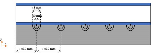
A three-dimensional schematic of the simulated SAWH, including the glass cover, air channel, absorber (consisting of the absorber plate and water tubes), and insulation layer, is shown in Figure 1. As illustrated, five water tubes are installed beneath the absorber plate, each with a semi-circular cross-section. For a clearer illustration of the water tube configuration, a two-dimensional cross-sectional view of the SAWH in the xy-plane is presented in Figure 2. As shown in Figure 2, the water tubes have inner and outer diameters of 40 and 48 mm, respectively, and their centers are spaced 166.7 mm apart. These tubes are designed to provide a large surface area between the water flow and the elements. Key geometric parameters are listed in Table 1.

| Physical/thermal properties | Insulation layer | Glass sheet | Absorber plate | Water tubes |
|---|---|---|---|---|
| Length (mm) | 1000 | 1000 | 1000 | — |
| Thickness (mm) | 40 | 4 | 4 | 4 |
| Surface emissivity | — | 0.9 | 0.95 | 0.98 |
| Reflectivity | — | 0.03 | 0.03 | — |
| Transmissivity | 0 | 0.95 | 0 | 0 |
| Conductivity (W/m K) | 0.04 | 0.8 | 390 | 390 |
In this setup, water flows through tubes oriented perpendicularly to the direction of air convection. The reasoning behind this is that when the water and air flows are parallel in a SAWH, the majority of the heat transfer from the absorber is directed to the water. However, when the flows are perpendicular, the heat transferred to both the water and the air becomes more balanced and comparable.
The water enters the tubes with an inlet velocity of 1 cm/s, corresponding to a total mass flow rate of a 0.03 kg/s and a Reynolds number of ~290. Forced convection airflow enters the duct, which has a height of b = 4 cm, with a Reynolds number (defined as ) of 2088. This corresponds to an average inlet air velocity of 0.42 m/s, or a mass flow rate of = 0.02 kg/s, used consistently across all test cases. The outer surfaces of the SAWH are exposed to convection and surface radiation, represented by an equivalent heat transfer coefficient, heq, which accounts for both radiation and convection effects [40].
2.1. Governing Equations
As mentioned in the previous section, the Reynolds numbers for both air and water flows (2088 and 290, respectively) are below 2300, indicating a laminar flow regime. Note that for accurate and reliable numerical results, all thermophysical properties of air are considered temperature-dependent. The governing equations for the three-dimensional incompressible, steady cross flows of air and water, including continuity, momentum, and energy equations, are as follows:
Here, Qw and Qa represent the rates of heat transfer to the water and air, respectively, while qsun denotes solar irradiation, which is maintained at a constant value of 1100 W/m2 in this study. Arad represents the cross-sectional area receiving incident solar radiation, which, in this study, corresponds to the area of the glass.
2.2. Mesh Study and Validation
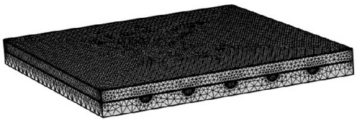
To ensure the reliability of the numerical findings, the results must be independent of grid size within the discretized computational domain, which necessitates determining the optimum number of elements. Since unstructured meshes offer flexibility in handling complex geometries and allow better control over element distribution, especially around critical regions with high temperatures or flow gradients. As shown in Figure 3, in this study, for modeling the SAWH an unstructured mesh is utilized. The grid independence study results are presented in Table 2, where the maximum absorber temperature values for five different grids, ranging from 45,026 to 228,390 elements, are reported. Among these, the grid with 22,440 elements, as given in Table 2, is identified as the optimum grid configuration.
| Number of elements | Tmax(C) | Error |
|---|---|---|
| 45,026 | 58.9 | 5.18 |
| 68,519 | 57.29 | 2.29 |
| 123,024 | 56.53 | 0.93 |
| 228,390 | 56.01 | — |
- Note: The bold values are the selected mesh for further study.
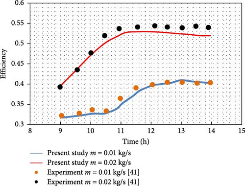
Simulations were conducted on a flat plate SAH and a SWH based on studies by Chabane et al. [41] and Alwan et al. [42]. The results from these simulations were then compared with experimental data from these references. The smooth duct SAH with a rectangular shape, studied in [41], was evaluated over a sunny day from 9 AM to 2 PM. Its efficiency, plotted in Figure 3, shows that collector efficiency increases with higher air mass flow rates. A comparison between the numerical results and experimental data in Figure 4 demonstrates good consistency, confirming the accuracy of the numerical model.
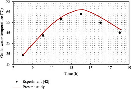
In the study by Alwan et al. [42], a novel-designed flat-plate SWH was introduced, featuring a galvanized steel plate with 30 copper tubes affixed to its surface. This solar collector was analyzed using both theoretical and experimental approaches to evaluate its thermal performance. In this system, solar irradiation is absorbed by the galvanized plate, which then transfers the heat to the copper tubes mounted on its surface. As water flows through these tubes, it absorbs thermal energy by forced convection, effectively heating the water as it circulates through the system. As shown in Figure 5, our numerical simulation results closely align with the experimental data with a high level of accuracy.
3. Results
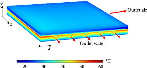
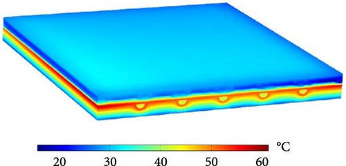
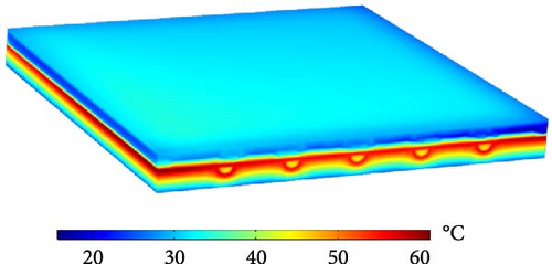
In this section, the numerical results for the simulated SAWH are presented under an incident radiation of 1100 W/m2, with constant air and water mass flow rates of 0.02 and 0.03 kg/s, respectively. The inlet water temperature (Tw in) significantly affects the thermal behavior of the solar collector; therefore, its performance is analyzed at three different inlet temperatures: 32, 37, and 42°C. Figure 6 illustrates the isotherm plots across the solar collector domain. The maximum temperature is observed near the absorber plate, where the incident radiation is directly absorbed, while the minimum temperature is located within the insulation. The glass cover exhibits a relatively high temperature due to the surface-to-surface radiation from the heated absorber. A comparison of the isotherm plots in Figure 6 highlights the strong influence of Tw in on the thermal behavior of the SAWH, particularly near the water tubes. While the overall temperature distribution pattern remains consistent, a significant increase in the temperature throughout the SAWH is observed as the Tw in rises.
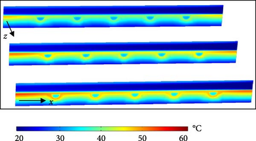
The temperature distributions at different y–z planes along the x-axis are presented in Figure 7. These temperature slices illustrate the thermal behavior of the SAWH in detail. A high-temperature region is observed near the absorber plate due to its direct exposure to incident solar radiation. This region shows a progressive temperature increase along the water flow direction inside the solar collector, with the maximum temperature occurring at the axial plane z = L, where the water has absorbed the most heat. Figure 7 also emphasizes the significant impact of Tw in on the overall thermal performance of the SAWH. As depicted, the temperature around the water tubes rises notably as Tw in increases from 32 to 42°C. This increase is particularly evident in areas adjacent to the water tubes, where heat transfer between the absorber plate and the flowing water is most intense.
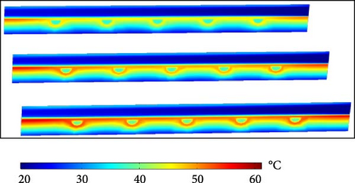
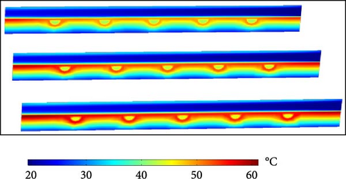
As the absorber plate is the main component of a solar collector, its temperature distribution, including the attached water tubes, is illustrated in Figures 8 and 9 from the top and bottom views, respectively. Figures 8 and 9 show two high-temperature zones near the corners of the absorber plate at the outlet section (z = L), with the highest temperature occurring near the air inlet section (x = 0). Figures 8 and 9 also highlight that an increase in the inlet water temperature leads to a considerable rise in the absorber’s temperature. Moreover, variations in the outlet water temperature across the five water tubes are observed. As shown in Figure 8, the highest outlet water temperature is recorded in the first tube, while the lowest is in the middle tube. A notable observation from Figures 8 and 9 show the relatively low maximum temperature of the absorber plate, ~60°C, in the designed solar collector. This is a desirable feature, as it prevents excessive heating of the glass cover, thereby reducing energy losses to the environment. Maintaining a lower glass cover temperature ensures better system efficiency by minimizing heat dissipation.
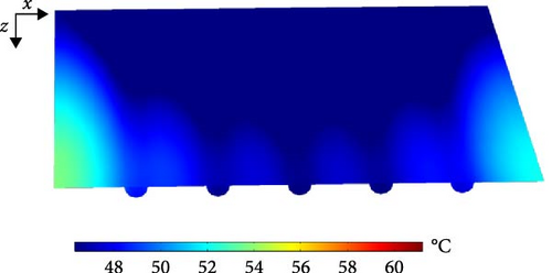
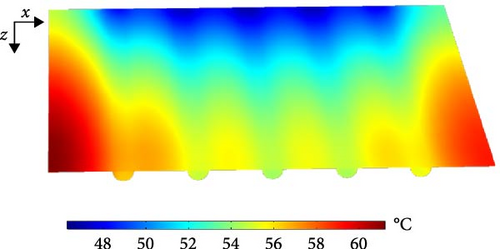
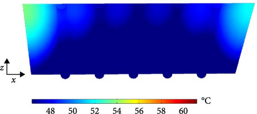
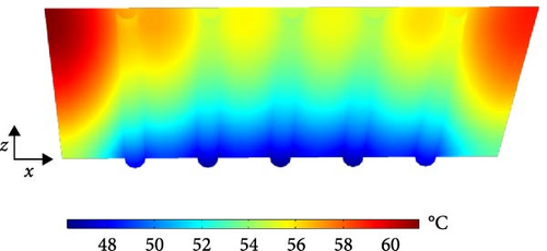
Figure 10 illustrates the temperature distribution of water along the length of the tubes for three different inlet temperatures. As shown, the temperature of water in all five tubes increases progressively along their length, while the first and last tubes absorb more heat than the others. That is because the first and last tubes exchange heat with the insulated walls on one side and with adjacent tubes on the other side. In contrast, the middle tubes exchange heat with adjacent tubes on both sides. As a result, the first and last tubes are likely at a higher temperature than the middle tubes, which are surrounded by other tubes on both sides.
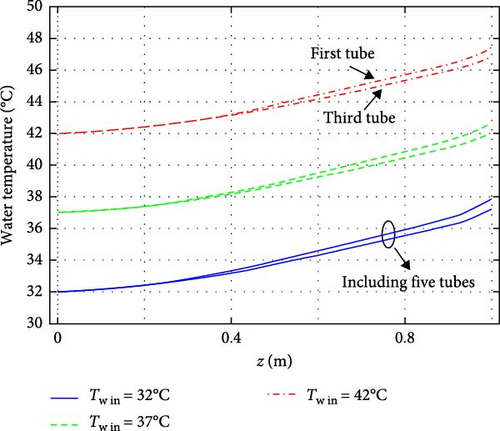
Additionally, the amount of temperature increase in water flow from the inlet to the outlet section decreases as the inlet temperature rises from 32 to 42°C. More precisely, the outlet temperatures corresponding to inlet temperatures of 32°C, 37°C, and 42°C are 38.25°C, 42.88°C, and 47.5°C, respectively, resulting in temperature gradients of 6.4, 6.03, and 5.65°C. This slight reduction in the rate of heat gain by the flow of water occurs because the higher inlet temperatures reduce the temperature difference between the tubes and the absorber, leading to a lower rate of heat transfer.
For better visualization of the heat gain in the water tubes, Figure 11 presents the temperature contours along the tube lengths for different inlet temperatures. As observed, the tube temperatures increase from inlet to outlet, reaching their maximum at the outlet. Additionally, the temperature rise in the middle tubes is lower compared to the first and last tubes for all three inlet temperatures. Figure 12 illustrates the temperature variations over the glass cover and absorber plate at the mid-plane z = L/2 along the x-axis. Except for the two ends at x = 0 and x = L, where local temperature minima are observed, the glass cover maintains an almost uniform temperature. Additionally, an increase in glass temperature is observed as Tw in gets to a higher value. Figure 9b shows a wavy variation in the absorber plate temperature caused by the presence of water tubes, with the minimum temperature occurring at the center of the plate.
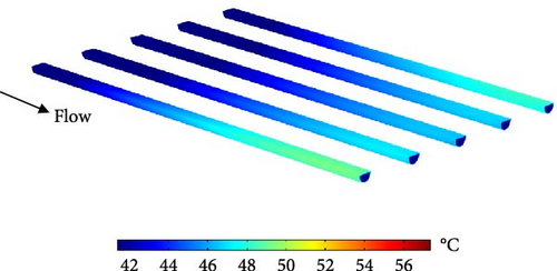

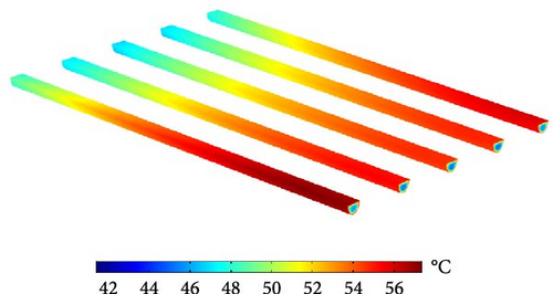
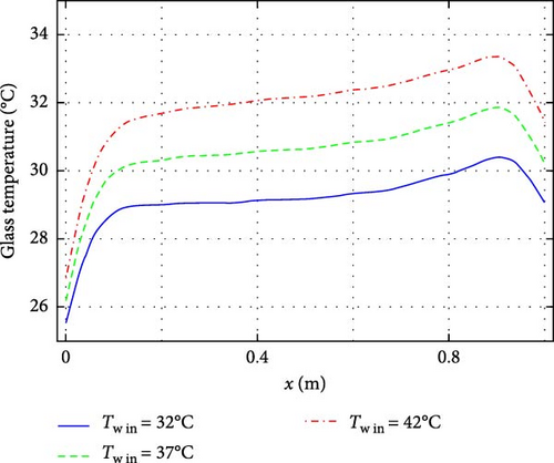
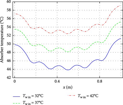
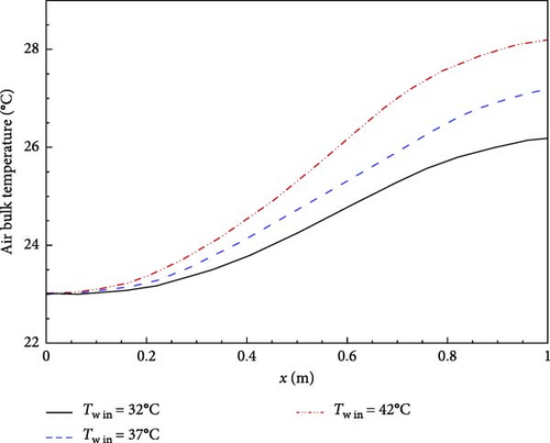
Figure 13 shows the variation of air bulk temperature along the SAWH for three different inlet water temperatures. The air bulk temperature increases gradually from the inlet to the outlet, along the airflow direction, such that the maximum air outlet temperature belongs to the one with Tw in = 42°C.
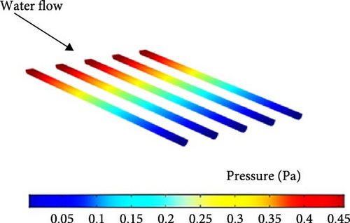
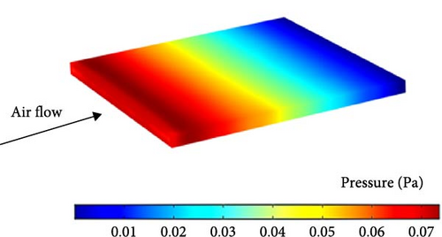
To assess the pumping power and pressure drop in the present SAWH system, pressure contours for both the water tubes and the air passage at mass flow rates of 0.03 kg/s for water and 0.02 kg/s for air are presented in Figure 14. As shown in Figure 14a, the pressure drop along the water tubes is less than 1 Pa (Figure 14b), indicating that the semi-circular cross-section of the tubes contributes to this low-pressure drop, facilitating smooth water flow while maintaining efficient heat transfer. On the air side, the pressure drop is below 0.1 Pa. These results demonstrate that the overall pressure drop in the SAWH system is very low, suggesting minimal resistance to fluid flow.
The amounts of heat gained by the air and water flows at different values of the water inlet temperature are studied in Figure 15. Figure 15 also shows the variation of thermal efficiency with water inlet temperature for the SAWH operating under a solar irradiation of 1100 W/m2. As illustrated, the heat transfer rate for the waterside decreases from ~788 to 695 W as the water inlet temperature gets to a higher value. This decrease is due to the reduction of temperature difference between the water flow and the heated surface. Conversely, the heat transfer rate on the air side increases from 120 to 157.6 W as the water inlet temperature rises. The thermal efficiency of the SAWH was also evaluated for different water inlet temperatures, by the results shown in Figure 15 on the left y-axis. The efficiency decreases from 82.5% to 77.5% as the inlet temperature increases, highlighting the significance of the heat transfer rate on the waterside.

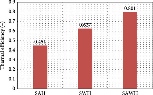
For comparison, the thermal efficiencies of a single-purpose SAH and a SWH with similar geometries, operating under the same conditions (air mass flow rate of 0.02 kg/s for SAH and water mass flow rate of 0.03 kg/s for SWH) are computed, and the results are shown in Figure 16. The results shown in Figure 16 highlight the superiority of the present SAWH, which has a thermal efficiency of 0.801, the highest compared to both the SAH and SWH. Specifically, the SAWH exhibits 77.6% higher efficiency than the SAH and 27.8% higher than the SWH.
In previous sections, the mass flow rates of air and water were considered constant at 0.02 kg/s and 0.03 kg/s, respectively. In this section, the effects of varying these mass flow rates on the thermal efficiency of the SAWH at a water inlet temperature of 37°C are investigated, and the results are presented in Figure 17. To study the effect of air mass flow rate, the water mass flow rate was fixed at 0.03 kg/s, and vice versa; to study the effect of water mass flow rate, the air mass flow rate was fixed at 0.02 kg/s.
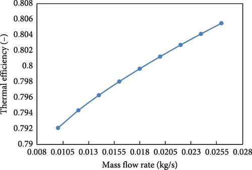
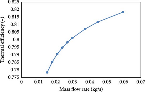
As shown in Figure 17, increasing both air and water mass flow rates enhances the thermal efficiency of the SAWH. Specifically, Figure 17a shows that increasing the air mass flow rate from 0.01 to 0.026 kg/s raises thermal efficiency from 0.792 to 0.806, a 1.77% improvement. Similarly, as shown in Figure 17b, increasing the water mass flow rate from 0.015 to 0.06 kg/s improves thermal efficiency from 0.78 to 0.82, a 5.13% increase. The more pronounced effect of water mass flow rate on thermal efficiency is primarily due to water’s higher thermal capacity and convective heat transfer coefficient. As a result, increasing the water mass flow rate has a stronger impact on overall system efficiency.
4. Conclusion
- 1.
The absorber plate exhibited the highest temperatures near the air inlet and outlet sections, with a maximum of ~60°C. This relatively low-temperature regulation minimizes excessive heating and energy losses.
- 2.
The water temperature increased progressively along the tube length, with the outlet temperature rising from 38.25 to 47.5°C as Tw in increased from 32 to 42°C. However, higher inlet temperatures resulted in reduced temperature gradients, leading to a decrease in heat transfer rates on the waterside.
- 3.
The average absorber temperature in the designed solar collector is relatively much lower than that of the conventional type due to the high rate of convection heat transfer from the heated surface into the working fluids. This behavior effectively decreases the rate of heat loss from the thermal system.
- 4.
The heat transfer rate on the waterside decreases as the inlet temperature rises, attributed to the reduced temperature difference between the water tubes and the absorber plate. In contrast, the heat transfer rate on the air side increases with higher inlet water temperatures.
- 5.
The thermal efficiency of the SAWH is 77.6% higher than that of a comparable single-purpose SAH and 27.8% higher than that of a SWH.
- 6.
Increasing air and water mass flow rates improve thermal efficiency, with water having a greater impact due to its higher thermal capacity. A rise in the water mass flow rate from 0.015 to 0.06 kg/s enhances efficiency by 5.13% while increasing the air mass flow rate from 0.01 to 0.026 kg/s improves it by 1.77%.
Nomenclature
-
- b:
-
- height (m)
-
- V:
-
- average velocity (m/s)
-
- Dh:
-
- hydraulic diameter (m)
-
- Arad:
-
- area of receiving incident solar radiation (m2)
-
- :
-
- mass flow (kg/s)
-
- V:
-
- velocity (m/s)
-
- P:
-
- pressure (Pa)
-
- Qwater:
-
- rate of heat transfer in waterside (W)
-
- Qair:
-
- rate of heat transfer in air side (W)
-
- qsun:
-
- sun irradiation (W/m2)
-
- V:
-
- velocity (m/s)
-
- T:
-
- temperature (K)
Greek Letters
-
- µ:
-
- dynamic viscosity (Pa.s)
-
- ρ:
-
- fluid density (kg/m3)
-
- ηth:
-
- thermal efficiency (-)
-
- β:
-
- coefficient of thermal expansion (1/K)
Subscript
-
- w:
-
- water
-
- a:
-
- air
-
- abs:
-
- absorber
-
- w in:
-
- water inlet
-
- th:
-
- thermal.
Conflicts of Interest
The authors declare no conflicts of interest.
Funding
The authors received no specific funding for this work.
Open Research
Data Availability Statement
Data sharing is not applicable to this article as no datasets were generated or analyzed during the course of this study.


