Enhancing Lifetime and Reliability in WSNs: Complementary of Dual-Battery Systems Energy Management Strategy
Abstract
Wireless sensor networks (WSNs) are often deployed in remote environments where battery maintenance is infeasible, making energy efficiency and system longevity critical. Traditional single-battery systems in WSNs suffer from performance degradation due to deep discharges, fluctuating loads, and lack of redundancy. This paper presents a novel hybrid energy management system that integrates dual LiFePO4 batteries with a supercapacitor, controlled through an adaptive state-of-charge (SoC)-based switching algorithm. The proposed architecture distributes charge–discharge cycles across two batteries and offloads transient peak demands to the supercapacitor, significantly reducing battery stress and extending operational lifespan. Unlike previous approaches, this system enables simultaneous charging and load powering and is specifically optimized for energy-harvesting WSN environments. Simulation results in MATLAB/Simulink demonstrate that the system improves battery lifespan by up to 25% compared to conventional single-battery configurations, while ensuring stable voltage regulation and improved reliability under variable loads. This strategy offers a scalable, resilient, and cost-effective power management solution for next-generation WSN deployments.
1. Introduction
Wireless sensor networks (WSNs) are becoming ever more utilized across a broad variety of applications, such as environmental monitoring, precision agriculture, industrial control, and smart infrastructure systems [1–3]. Typically, such networks are comprised of geographically dispersed sensor nodes that must function autonomously for long periods of time—often in inaccessible or remote areas where routine maintenance and battery replenishments become infeasible. For this reason, energy efficiency and system reliability have become key design considerations in the creation of sustainable WSNs. WSN nodes usually employ single lithium-based batteries as the only power supply because of their energy density, compact size, and commercial availability [4]. The battery will experience degradation with the passage of time, particularly under operating scenarios of high charge–discharge cycle rates, deep discharge, and varying load profiles [5]. These degradations have a direct impact on the operational lifetime and reliability of sensor nodes, ultimately limiting the scalability and robustness of the network as a whole. While energy-harvesting approaches, such as photovoltaic, thermal, or kinetic sources, have been proposed to remedy these issues, their dependence on environmental conditions introduces variability and typically requires complex power management circuitry [6]. To overcome these constraints, contemporary studies have investigated hybrid energy storage systems that integrate batteries with supercapacitors, thereby utilizing the advantageous characteristics of both [7, 8]. Among the diverse range of battery chemistries, lithium iron phosphate (LiFePO4) has attracted considerable interest due to its extended cycle life, elevated thermal stability, and intrinsic safety features, rendering it especially appropriate for prolonged, unattended deployments in WSNs [9]. At the same time, supercapacitors exhibit excellent power density and rapid charge–discharge capability and are best suited for managing transient loads and alleviating high-power requirements from batteries, thus minimizing stress and enhancing their operational lifespan [10]. In this paper, we propose a novel energy management technique that couples dual LiFePO4 batteries with a supercapacitor in a complementary arrangement for WSN applications. Unlike previous works that primarily adopt either a single-battery [7] or basic dual-battery setups with static control [8], our approach introduces a dynamic switching mechanism that integrates two LiFePO4 batteries and a supercapacitor, enabling real-time state-of-charge (SoC)-based load balancing. This configuration is uniquely tailored for WSNs under variable environmental conditions, allowing for simultaneous energy harvesting and delivery. The proposed system mitigates deep discharges, absorbs transient loads, and improves average node lifespan by 25%, demonstrating a novel and practical advancement over state-of-the-art systems. This configuration not only balances the discharge cycles between batteries but also offloads peak current demands to the supercapacitor, thereby minimizing degradation and enhancing energy reliability.
To the best of our knowledge, this is the first time such a hybrid configuration is applied to WSNs with dynamic switching logic tailored for real-time load profiles. The suggested framework incorporates a high-performance control system that continuously tracks the SoC for each individual battery and adaptively switches among them according to predefined threshold levels. A supercapacitor is utilized as a buffer with a quick response to inhibit power fluctuations and aid in transient peak loads, which enhances the entire system’s energy efficiency and robustness.
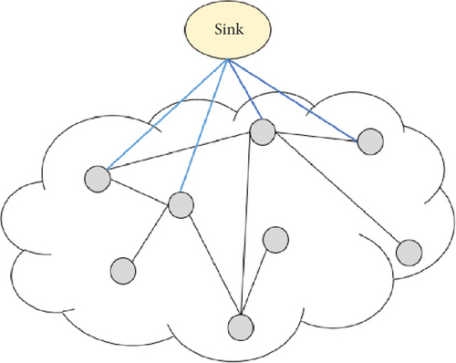
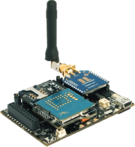
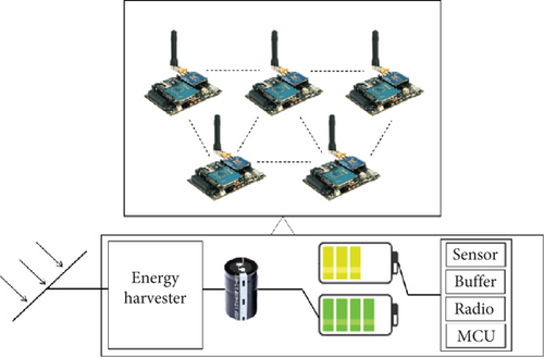
The configuration of the system is illustrated in Figure 1, in which the integration of batteries and supercapacitor and the control unit are represented. The SoC level-based and load-based switching approach is also illustrated in more detail in Figure 2, providing a graphical representation of the decision-making logic utilized within the controller.
- •
Design and integration of a dual-battery–supercapacitor hybrid power system for WSNs;
- •
The design of SoC-based control algorithm for intelligent energy management and switching;
- •
An exhaustive measure of performance exhibits high reliability and noteworthy prolongation of operational life. This work presents an affordable and scalable approach to power management in resource-constrained WSN environments, with applicability to a wide range of real-world deployments.
The rest of the paper is organized as follows: Section 2 examines recent research on strategies for extending the lifespan of WSN nodes, with a special emphasis on battery-related studies. While energy-efficient routing and battery management in WSNs have been discussed in Section 2, most of the effective energy management strategies have yet to consider dynamic environmental conditions for practical adaptation. Section 3 introduces our new approach to filling this gap by using dual-battery systems. Section 3 describes the specific solution under investigation, as well as relevant information and supporting research. Section 4 presents a detailed explanation of our solution as well as the simulations that support it. Finally, Sections 5 and 6 present our findings and compare them to previous research.
2. Related Works
Energy efficiency remains a central concern in the design of WSNs, particularly due to the high energy demands of wireless data transmission compared to local data processing. Since sensor nodes are typically battery-powered and deployed in remote or inaccessible areas, reducing energy consumption at every layer of operation is vital to prolonging the network’s lifetime. Consequently, numerous energy-aware strategies have been proposed, particularly in the domains of routing protocols, data aggregation, and energy harvesting. In the realm of energy-efficient routing, many works have focused on minimizing redundant transmissions and optimizing communication paths. Studies such as [12] have explored temporal and spatial data aggregation to reduce energy waste, while [13] proposed robust routing protocols designed to counteract attacks that deplete node energy. Various approaches—ranging from hierarchical and data-centric routing [14] to location-based and clustering schemes—have been investigated to optimize data flow and reduce transmission costs. Novel data dissemination methods based on distributed hash tables (DHTs) and Chord-inspired protocols have also been explored in [15, 16], aiming to reduce communication overhead. In parallel, artificial intelligence techniques [17], genetic optimization methods [18], and machine learning algorithms [19] have been increasingly applied to predict node behavior and optimize energy consumption dynamically. Beyond communication protocols, considerable attention has been given to power architecture and energy storage optimization. For instance, [9] introduced a supercapacitor-assisted single-battery system to improve transient response, although it relied on static threshold-based switching and lacked adaptability to fluctuating loads. Similarly, [10] proposed a dual-source system, but without dynamic coordination, which limited its effectiveness in reducing deep discharge cycles. Work [19] further advanced hybrid storage by incorporating supercapacitor buffering, yet did not implement intelligent load balancing or real-time SoC-based switching logic.
More recent work has shifted toward practical hardware and control-level power management in resource-constrained environments. Bathre and Das [20] presented a fuzzy logic–based smart energy controller for self-powered WSNs, implemented using Arduino and Proteus simulations. While their work demonstrates software-level adaptivity, it does not address hardware-level energy distribution or hybrid storage scalability. Similarly, Kirubakaran et al. [21] developed a WSN-IoT-based monitoring system for coal mines, highlighting the importance of fault-tolerant power design in inaccessible deployments. These studies reinforce the need for integrated, intelligent power architectures in modern WSNs.
In contrast to prior methods, our proposed system introduces a coordinated dual-battery energy management strategy enhanced with a supercapacitor buffer and an adaptive SoC-based switching algorithm. This approach dynamically distributes energy delivery across two LiFePO4 batteries and offloads high-frequency load fluctuations to the supercapacitor. Unlike static control schemes in [9, 10], our controller adjusts switching logic in real time based on load and SoC conditions. The resulting system enhances both long-term battery resilience and transient response, making it especially suitable for energy-harvesting WSNs, low-maintenance deployments, and variable-load environments.
3. Materials
- →
First condition: The model will not function properly if the energy transfer time from the harvester to the charging battery exceeds the time it takes to recharge the sensors before complete discharge. This failure occurs when the battery powering the sensors discharges completely before the charging battery receives adequate energy, causing the fully charged battery to transition from charging to supplying power to the sensors.
- →
Second condition: The model may fail if the time it takes to transfer energy from the energy harvester to the battery is shorter than the time it takes to fully charge the sensors and discharge. In this scenario, the battery connected to the energy harvester will be fully charged before the battery powering the sensors is completely depleted. As a result, until the sensor-connected battery is completely discharged, the status of both batteries remains unchanged. During this time, despite being fully charged, the battery connected to the energy harvester must continue drawing energy from it, reducing its lifespan.
In conclusion, this concept can only be effectively implemented if we ensure that the charging time for the battery connected to the energy harvester closely matches that of the battery connected to the sensors. However, in practice, such certainty is elusive due to environmental variables; changes in weather and ambient conditions cause varying energy yields from the harvester at different times of day and night.
3.1. Lead–Acid Batteries
Lead–acid batteries are some of the oldest types of batteries still in use today. Invented in 1859 by French physicist Gaston Plante, this traditional technology has been widely used due to its reliability and relatively low cost. Lead–acid batteries are typically found in automobiles, backup power systems and renewable energy storage. One of the most distinguishing features of lead–acid batteries is their weight and size in comparison to other types of batteries. They have a lower energy density, indicating that they can store less energy per unit of weight. For example, a typical lead–acid battery could weigh anywhere from 15 to 30 kg. The electrolyte in these batteries is sulfuric acid, and the battery operates through a chemical reaction between the lead plates and the acid. Lead–acid batteries have a cycle life of approximately 300 cycles and require routine maintenance. They are also less efficient, with approximately 80% of the energy put into the battery being retrievable.
3.2. Lithium Batteries
Lithium batteries are a more advanced, high-performance technology. They were first introduced in the 1970s and have undergone significant evolution. Lithium batteries are known for their high energy density, lightweight design, and long lifespan. The advantages of lithium batteries over lead–acid batteries are higher energy density, longer lifespan, faster charging, and less maintenance. Lithium batteries are used extensively in consumer electronics, electric vehicles, and renewable energy systems. They can last from 1000 to 2000 cycles, which is significantly longer than lead–acid batteries. Their higher efficiency (around 90%) means that more of the energy stored in the battery can be used.
3.3. LiFePO4 Batteries
LiFePO4 batteries, also known as lithium iron phosphate batteries, are an advanced type of lithium battery. They use LiFePO4 as a cathode material, which provides several advantages over other lithium batteries. The advantages of these types of batteries are mentioned in Table 1.
| Safety | Compared to other lithium-ion batteries, they are more stable and less likely to cause thermal runaway or fire |
| Long lifespan | LiFePO4 batteries have a long lifespan, allowing for thousands of charge–discharge cycles |
| Wide temperature range | They perform well across a broad range of temperatures |
| High discharge rates | These batteries provide high-power output for demanding applications |
LiFePO4 batteries have a long cycle life, often exceeding 2000 cycles, and can maintain up to 80% capacity even after extensive use. They can withstand high discharge rates and operate in extreme temperatures ranging from −20°C to 75°C. Their efficiency is the highest of the discussed types, reaching up to 95%. LiFePO4 batteries are commonly used in applications that require safety and longevity, such as electric vehicles, energy storage systems, and marine and RV batteries.
3.3.1. Damaging and Overloading
If a lithium-ion battery is damaged, crushed, or subjected to a higher electrical load without overcharge protection, problems can occur. External short circuits can cause a battery explosion [23]. Such incidents can occur when lithium-ion batteries are not properly disposed of and are thrown away alongside other waste. Recycling companies’ handling of them can cause damage and fires, resulting in large-scale conflagrations. Twelve such fires were reported in Swiss recycling facilities in 2023 [24]. Li-ion batteries can overheat or overcharge, resulting in thermal runaway and cell rupture [25]. During thermal runaway, internal degradation and oxidation processes can keep cell temperatures above 500°C, potentially igniting secondary combustibles and resulting in leakage, explosion, or fire [26]. To mitigate these risks, many lithium-ion cells (and battery packs) include fail-safe circuitry that disconnects the battery when the voltage exceeds the safe range of 3–4.2 V per cell, or when it is overcharged or discharged. Lithium battery packs that lack effective battery management circuits, whether built by a vendor or an end user, are vulnerable to these issues. Poorly designed or implemented battery management circuits can also cause issues; it is difficult to determine whether any specific battery management circuitry is properly implemented.
In conclusion, understanding the distinctions between these types of batteries is critical for selecting the best battery for your requirements. Many traditional applications benefit from lead–acid batteries, which are dependable and affordable. Lithium batteries provide superior performance and longer life, making them ideal for modern electronic devices and electric vehicles. LiFePO4 batteries provide superior safety and durability, ideal for high-demand and critical applications. Lithium-ion batteries, particularly the LiFePO4 variety, are widely used in modern devices. While this type of battery has many advantages, including high power and energy density, a large number of charge and discharge cycles, and low self-discharge, it also has significant drawbacks. In particular, there is a significant risk of cell damage due to excessive discharge or overcharging. The study seeks to determine the potential risk of cell damage caused by differences in their initial SoC. It also looks into whether successive charge and discharge cycles help to reduce or exacerbate differences in energy storage between individual cells in the pack. The investigated LiFePO4 batteries are primarily used in low-power portable devices like mine-laying and mine-clearing equipment, as well as WSNs.
3.3.2. Charging Mode
3.3.3. Discharge Mode
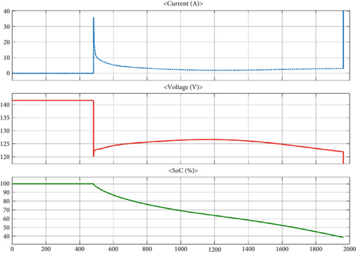
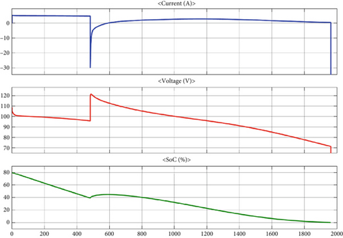
A LiFePO4 battery charging and discharging with SoC control is simulated in MATLAB in Figures 3 and 4.
The most common battery charging methods include constant current–constant voltage (CC-CV) charging, multistage constant current (MCC) charging, pulse charging, and constant temperature–constant voltage (CT-CV) charging [27]. CC-CV charging is the most commonly used method. Nevertheless, high currents during the constant current phase can cause lithium deposition on the graphite electrode, resulting in a significant reduction in battery capacity [28]. In the case of lithium-ion batteries, the upper limit for current intensity during constant current charging is typically set to a low value [29]. Yang et al. [30] proposed an asymmetric temperature modulation technique in which the self-heating battery configuration can increase the battery temperature by 0.8°C/s. This method rapidly preheats the lithium-ion battery to 60°C during charging, allowing it to reach a SoC of 80 in less than 10 min at a current of 6C. The increased temperature improves the battery’s kinetics and transport properties while preventing lithium plating. To critically evaluate and compare the effects of conventional constant current charging and the UAD-MPC charging method on battery capacity degradation over multiple cycles, two batteries were charged and discharged over 600 times at ambient temperature (25°C). As the battery’s actual capacity decreases in the later stages of the aging test, charging at the rated capacity will inevitably result in lithium plating. Furthermore, the battery model contains inherent inaccuracies. Taking into account both battery aging and model accuracy limits, a charging capacity of only 80% is chosen for the algorithm’s performance evaluation in this study. The discharge process begins when the lower limit voltage is reached, and achieving a charge capacity equal to 80% of the original battery capacity is referred to as SoC = 80%. The charging capacity is determined using the ampere-hour integration method.
For batteries charged with constant current, both the charge and discharge currents are set at 1C. For batteries charged with the UAD-MPC charging technique, the simulated operating conditions generated by this method determine charge levels while maintaining a discharge current rate of 1C. In the experimental battery cycle aging framework, each charge and discharge cycle are separated by a 10-min interval, with an additional 10-min pause in between. To accurately determine the available capacity, the batteries are fully charged and discharged every 50 cycles. The model’s parameters are determined by conducting extensive battery charge and discharge experiments. The simulation inputs for the battery model include current rates of 0.1C, 0.5C, and 1C, with a simulation temperature of 25°C.
The verification experiment was carried out in a temperature-controlled chamber at a constant ambient temperature of 25°C. At constant currents of 0.1C, 0.5C, and 1C, the root mean square errors for predicted terminal voltage values during the model’s charging simulation were 0.018, 0.022, and 0.012 V, respectively. The mean square errors for the predicted terminal voltage values during the model’s discharge simulation were 0.041, 0.016, and 0.012 V, respectively. The ultrasonic tests using both the conventional constant current charging method and the UAD-MPC charging technique at a temperature of 15°C yielded remarkable results. Initially, the two batteries subjected to these different charging methods appeared nearly identical, with no visible signs of lithium plating. However, when the battery reached an 80% SoC using the constant current method, the ultrasonic signal showed significant changes. This lithium plating caused significant gas formation within the battery, resulting in the complete loss of the ultrasonic reflection signal from the back of the battery. Even at a temperature of 10°C, ultrasonic tests comparing both charging methods yielded results comparable to those at 15°C. Without lithium plating, both batteries appeared to be nearly identical. However, when using the constant current method to achieve SoC = 80%, significant changes in the ultrasound signal were observed, with the reflection signal almost completely disappearing. In contrast, no significant changes in the ultrasonic signal were observed in the battery charged using the UAD-MPC method at SoC = 80%.
Gas formation occurred in this battery during continuous charging, but it was much less pronounced than under constant current conditions. The main reason for this discrepancy is the low consistency of the chemical reactions that occur at high SoC values and result in local gas production. However, when compared to constant current charging, gas formation was significantly reduced, as were the side reactions associated with lithium plating. At ambient temperatures of 10°C and 15°C, the UAD-MPC charging method could charge more than 80% (16 Ah) of the battery capacity before lithium plating, whereas the constant current method could only charge about 50% (10 Ah) before lithium plating. Throughout the charging process, the battery capacity remained relatively stable using the UAD-MPC method. The method proposed here is extremely important for improving the safety and reliability of battery systems.
3.3.4. Comparative Analysis of Battery States
In Equation (5), Cn represents the nominal battery capacity, I denotes the charge or discharge current, t represents the time, and T denotes the charging or discharging duration. It is important to note that for battery packs connected in series, this method cannot determine the level of SoC variation between individual cells because the current flowing through all cells remains constant. The energy distribution between the individual cells in the battery pack can be calculated by measuring the current and voltage on each cell during the charging and discharging process.
The energy provided or extracted by the batteries is then calculated using Equation (6). In this equation, EB represents the energy supplied or extracted by the battery, UB denotes the voltage measured at the battery terminals, I represents the charge–discharge current of the battery pack, t denotes the time, and T is the charge–discharge time. Ideally, the energy drawn while charging should match the energy delivered to the load during discharge. However, it is clear that battery efficiency is not 100%, with internal resistance playing an important role. According to a widely accepted Li-ion battery equivalence model, the series resistance is significantly influenced by the SoC and tends to rise as the SoC decreases. This phenomenon causes significant differences in energy storage between batteries with various SoC values. Based on the preceding analysis, voltage (UB) and energy (EB) measurements were taken to determine the degree of SoC deviation between the batteries in the tested pack. The objective of this study was not to determine an exact SoC value, but rather to look at how the individual batteries differed from one another after multiple charge and discharge cycles. A comparison of the UB at the end of the charge and discharge cycles was conducted.
The energy EB for each individual cell is calculated by numerical integration using the rectangular method, as shown in Equation (7) above. In this expression, represents the energy either supplied by or taken from battery Bn, while represents the voltage recorded at the terminals of battery Bn. The variable I denotes the charging or discharging current of the battery, t denotes the time, T represents the total duration of charging or discharging, and Δt denotes the interval between successive measurements, where m = T/Δt [32].
3.4. Techniques for SoC Estimation
There are two techniques for estimating SoC: battery voltage translation and battery current integration (Coulomb counting). Both techniques are useful, but neither can accurately estimate SoC in a Li-ion battery.
3.4.1. Voltage Translation
In most uses of energy storage, a simple voltmeter is adequate for a SoC indication since the battery voltage falls off rather linearly with discharge. Of course, this behavior depends upon the specific chemistry of the battery. For lead acid, there is a more pronounced drop in voltage as discharge occurs, so a good correlation exists between voltage and SoC. This relationship allows the calibration of voltmeters to provide an estimated SoC by translating the measured voltage levels. However, this approach suffers from serious drawbacks due to the fact that battery voltage is affected by factors such as fluctuations in ambient temperature and the magnitude of discharge or charge current. These deviations can be compensated for using various algorithms in order to make the voltage-based estimation of SoC more reliable across different conditions. Lithium-ion batteries, however, are particularly challenging for this type of approach. The voltage of a Li-ion cell remains fairly constant within a large portion of its SoC range, and hence, voltage translation cannot be practically applied as a continuous SoC estimation method. Despite this limitation, Li-ion batteries actually have quite extreme voltage variations at the limits of their charge cycle: At full charge, voltage rapidly increases; when nearing full depletion, the voltage falls strongly. Therefore, voltage translation can be quite effective for SoC estimation, majorly at very high or very low levels of charge. These simple voltage measurements have been significantly extended by more sophisticated techniques, such as Coulomb counting, Kalman filtering, and machine learning–based predictive models, in order to arrive at an SoC estimation. Coulomb counting measures the net charge in and out of the cell, while Kalman filtering increases accuracy by estimating internal states based on observed and modeled behavior. Additionally, EIS has been one of the advanced techniques to determine SoC and SoH based on the examination of battery impedance at different frequencies. Contemporary BMS integrates these complementary techniques along with voltage-based SoC estimation for more accurate and reliable performance in a wide range of applications, from electric vehicles to renewable energy storage systems.
3.4.2. Battery Capacity
The capacity of a battery is the amount of energy that can be stored and delivered under specified conditions. It is conventionally given in ampere-hours or watt-hours. Ampere-hour defines the current that a battery can provide over a certain period, while watt-hour considers both current and voltage, and therefore, it is a more complete measure of energy storage. A 10 Ah battery, for example, could theoretically supply 10 amps for 1 h or 1 amp for 10 h under ideal conditions. Real-life performance, however, depends on a range of factors, including discharge rate, temperature, and aging. The capacity of a battery is measured through specific standardized tests so that exactitude and reliability can be maintained. One of the most common ways is the 20-h rate test. It is done by the complete discharge of the fully charged battery at constant current down to a predefined cutoff voltage, which generally is 1.75 V/cell in the case of lead acid and 2.5 V/cell for lithium-ion systems. The rated capacity is obtained as the ampere-hours delivered before this cutoff voltage reaches it. Other test methods include C-rate testing, a way to define how fast the battery will charge or discharge with respect to its capacity: A 1C rate means discharging a battery at its full capacity in 1 h, while a 0.5C rate would discharge the same battery in 2 h. Peukert’s law has described how the capacity falls off at higher discharge rates due to internal resistance and inefficiencies that are very specific to lead acid and most other battery chemistries. The more complex internal resistance analysis and degradation, with EIS-informed insights, has been made not only on the SoC but also on the state of health [33]. A number of factors affect battery capacity beyond its rating in ampere-hour. Temperature is important because both high temperatures and extreme lows have massive impacts on battery performance. The lithium-ion battery, for example, has its capacity loss when exposed to cold temperatures and shows accelerated degradation at higher temperatures. The depth of discharge (DoD) influences life because the more the cycle of discharge is deeper, the smaller the general lifespan and effective capacity within the lead–acid and lithium-based chemistries [34]. Besides, there are also several more concerns about battery age and cycle life since, with time, chemical degradation leads to capacity fade. Thus, a lithium-ion battery, depending on usage conditions, generally loses 10%–20% of its capacity after 500 cycles. The efficiency depends on the charge and discharge rates. Thus, higher discharge currents result in voltage drops and heat generation, hence decreasing the available capacity. With aging, internal resistance increases, leading to greater energy loss as heat and lower usable capacity [35]. The modern concept of BMS has implemented multiple techniques to perform active thermal management, intelligent algorithms for charging techniques like pulse charging or trickle charge to optimize the charge cycle of the battery, and cell balancing for multicell batteries to ensure that cells are charged up uniformly [36]. Additionally, predictive maintenance through AI and machine learning methods can estimate the degradation and enable the optimization of battery usage for maximum capacity and life. With an understanding of battery capacity in greater detail, there comes better energy storage design, improvement in battery performance, and also more reliable applications in electric vehicles, renewable energy storage, and portable electronics.
3.4.3. Battery Voltage
Battery voltage refers to the electrical potential difference between a battery’s positive and negative terminals. It is measured in volts. The voltage of a battery influences its ability to provide power to a load. Higher voltage batteries can generate more power, making them ideal for high-power applications. The typical voltage levels for batteries vary according to their type and application. For example, lead–acid batteries are commonly available in 12 V configurations, whereas lithium-ion batteries are available in a variety of voltages, including 12, 24, 36, and 48 V. The voltage also influences the battery’s efficiency and performance, which affects its overall run time.
3.4.4. Battery Efficiency
Battery efficiency is the percentage of energy stored in the battery that can be recovered during discharge. Different batteries have varying levels of efficiency. Lead–acid batteries, for example, have an efficiency of around 80%, which means that 80% of the energy stored in the battery can be recovered. Lithium-ion batteries typically achieve 90% efficiency, while LiFePO4 batteries can reach up to 95%. Efficiency is an important factor in determining how well a battery will power a load. High-efficiency batteries waste less energy, resulting in more usable power and longer battery life.
3.4.5. Load Power
Load power is the amount of power used by the device or system that is connected to the battery. It is measured in watts (W). Load power has a direct impact on the battery’s discharge rate and, thus, its run time. A higher load power depletes the battery more quickly, whereas a lower load power allows the battery to last longer. The lead acid, lithium, and LiFePO4 battery run time calculator takes into account battery capacity, voltage, efficiency, and load power to estimate battery life under a given load. The importance of each factor in estimating battery performance is summarized in Table 2.
| Battery capacity | Determines the total energy available for the load |
| Battery voltage | Affects the power delivery and compatibility with the load |
| Battery efficiency | Influences the amount of usable energy and overall performance |
| Temperature coefficient | Adjustment factor based on the temperature |
| SoC | State of charge (as a decimal, e.g., 0.8 for 80% SoC) |
| Load power | Dictates the rate at which the battery is discharged |
| Discharge rate factor (DRF) | Adjustment factor based on the discharge rate |
This equation provides an estimated run time based on the input values. t represents time (hour); C denotes the capacity (ampere-hour); V represents the voltage (volt); E is the efficiency; T represents the temperature coefficient (T); SoC represents the current charge level of the battery, expressed as a fraction of total capacity; L denotes the load power (watts); and D represents the discharge rate factor.
- 1.
No charging and discharging at the same time.
- 2.
Switching within the mentioned range.
The effects of incorporating a supercapacitor into the physical structure of the nodes—along with managing battery charge and discharge cycles within the specified SoC interval and considering battery efficiency—are analyzed in this work [40].
4. Proposed Method
4.1. Energy Storage Buffering, Supercapacitor Integration
Fluctuations in input power: Variations in input power can pose significant challenges when the energy supply source is directly connected to the batteries, as these rapid fluctuations can significantly shorten their operational life. To address this issue, the use of a capacitor as an energy buffer between the power source and the batteries is proposed. Notably, supercapacitors have a longer lifespan than traditional batteries, which alleviates concerns about the supercapacitor failing before the batteries. A supercapacitor is a high-speed energy buffer that can quickly absorb and release energy. This feature is critical for managing short bursts of energy from an energy harvester (such as solar panels or piezoelectric devices). When the energy-harvesting conditions are optimal, the supercapacitor charges quickly. A detailed breakdown of the benefits of integrating a supercapacitor into the WSN node is presented in Table 3.
| Fast response | Supercapacitors provide fast charging and discharging, making them ideal for intermittent energy supply applications. Supercapacitors can absorb energy quickly, shortening the charging time of the battery. This aspect can help to reduce inefficiencies |
| Longevity | They have a longer lifecycle than batteries, lowering maintenance and replacement costs |
| Reduction of charge and discharge cycles | Supercapacitors reduce charge and discharge cycles by storing and releasing energy quickly. This means that the battery has fewer deep charge and discharge cycles, which is a major contributor to battery degradation |
| Temperature management | Supercapacitors perform better at higher temperatures and can serve as a cooling system for batteries. Reducing extreme temperatures and temperature fluctuations can help extend battery life |
| Reduction of electrical stress | Smoother voltage and current control reduce electrical stress on the battery when transferring energy from the supercapacitor |
| Load support for sudden loads | Supercapacitors can support sudden loads, reducing battery stress and ensuring stability |
| Discharge rate factor (DRF) | Adjustment factor based on the discharge rate |
The main battery only charges when the supercapacitor reaches a specific voltage level, preventing the battery from being subjected to rapid input fluctuations. Supercapacitors have the remarkable ability to be charged and discharged hundreds of thousands of times with little loss in performance or quality. Their lifespan is significantly extended, ranging from 10 to 20 years. After a decade of operation, their capacity has decreased from 100% to 80%. Because of their lower equivalent series resistance (ESR), charging and discharging times are significantly shorter. They have higher power and current capabilities than conventional capacitors. Furthermore, they can withstand both high temperatures and extreme cold, down to −40°C.
When we incorporate a supercapacitor into the sensor’s physical structure, the batteries continuously supply energy through these capacitors. Otherwise, the batteries would have to receive it while solar energy is being converted into electrical energy. Unfortunately, this energy is not constantly available, and the connection between the batteries and the energy converter may be disconnected and reconnected several times throughout the day.
However, this will now occur with the supercapacitor, and because the supercapacitors have a much longer lifespan than the batteries, we will no longer be concerned about the capacitors failing before the batteries. The capacitor absorbs energy from the converter, and when one of the batteries reaches about 20% of its SoC, it begins charging it continuously. As shown in Figure 5, Battery I is being replenished by the solar energy collector, while Battery II is simultaneously discharging to meet the sensor node’s operational requirements, such as functionality and energy consumption during data transmission. It is also worth noting that a battery’s capacity decreases when only partially charged. This necessitates careful control over the conditions under which the roles of charging and discharging are switched between the two batteries. As a result, the batteries should only switch roles when one is fully charged and the other is fully discharged to ensure peak performance and longevity [9]. A significant challenge in the development of electronic devices is the careful selection of an appropriate power source. This issue is especially important for portable devices that must function in a variety of environments, such as military equipment, to delve deeper into the proposed solution for battery charging and discharging, with a focus on the integration of supercapacitors, threshold-based switching, and cell balancing system methods.
4.2. Threshold-Based Switching/Switch off
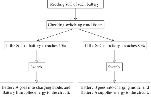
The intelligent power management strategy will help in extracting the maximum life from the battery with optimum energy efficiency in energy-harvesting systems. If the charge falls to about 20%, the system should start extracting energy from the harvesting source to maintain a constant energy supply and prevent deep discharging, which, over time, degrades the performance of the battery. On the other hand, it should stop energy harvesting whenever the battery’s charge level falls within an optimum range, for instance, from 80% to 90%, to prevent overcharging because it may speed up aging, which reduces the cycle life of a battery. For automated regulation of energy, the battery management system should also incorporate a sensor-actuated switch. The sensor is always monitoring the SoC of the battery and, based on a predefined threshold of SoC, sends a real-time command to the switch. At the top limit of the SoC threshold between 80% and 90%, the sensor signals the switch to disconnect the energy harvester from the battery in order not to have redundant charge cycles. Similarly, when the battery drains to 20% charge, the sensor triggers the switching mechanism to switch back the battery to the energy harvester. In such a way, this automatic switching allows for smooth transitions between energy sources and prevents wastage of energy. To refine this further, voltage thresholds should also be defined so that the charging–discharging process is well regulated. Energy transfer should occur only in cases when its voltage exceeds the specified level; energy is merely transferred if the excess is available within the supercapacitor/secondary energy storage unit. Also, power supplies from the major battery to sensor nodes are not called for, but until it attains a severe value of its SoC, the need for preserving remaining energy resources can easily be saved by employing very essential operations there. Adaptive power management algorithms, such as model-predictive control or reinforcement learning, can be integrated to further optimize energy distribution. These algorithms analyze historical energy usage patterns, predict future energy availability, and dynamically adjust switching thresholds for optimal performance. Integration of supercapacitors with rechargeable batteries will enhance system stability through rapid charge–discharge cycles, reducing stress on the primary battery and extending its operational lifespan. All these advanced energy management strategies are implemented in the proposed system for efficient energy harvesting, reduced unnecessary power losses, and an increased overall lifetime and reliability of the EH-WSNs.
4.3. Required Components and Circuit Design
- •
Two lithium batteries to store and supply energy.
- •
A charger circuit for recharging the batteries from the energy harvester.
- •
A switching circuit—such as a relay or MOSFET—that can quickly alternate between the two batteries based on control logic.
- •
Voltage and current sensors for each battery. Voltage sensors help estimate the SoC by measuring terminal voltage.
4.4. Control Algorithm
The switching mechanism between the batteries should be designed such that, based on the conducted research, the most optimal state is achieved. It is not necessary that switching occurs only when a battery gets near to its depletion; rather, it should switch within the targeted SoC range. The algorithm of this switching is presented in Figure 6.
To compare the working time of the batteries after implementing the proposed methods, based on Formula (8), it was shown that by adding the supercapacitor between the EH and the batteries and by compressing the battery charging range from [0, 100] to [20, 80] using the mentioned switch [33], the battery efficiency will increase. At the same condition, we have t ∝ E, so the run time of the battery would increase. By increasing the run time of the battery, the number of charging/discharging of the batteries will be decreased so that the lifetime of the batteries will be higher. To demonstrate that the battery’s lifespan increases, we can examine some technical and mathematical features and apply formulas.
- →
DoD: The percentage of battery capacity that can be discharged without damaging the battery.
- →
Cycle life: The number of times the battery can be fully charged and discharged.
- →
Discharge current: High discharge currents can lead to a reduction in battery lifespan.
- →
Reduced DoD: The DoD for the battery will be lower.
- →
Increased cycle life: Since the battery operates under more favorable conditions, its number of cycles increases.
By using a supercapacitor, the battery experiences less stress and undergoes less DoD, ultimately leading to an increased lifespan. This mathematical and technical analysis highlights the advantages of using supercapacitors in renewable energy systems.
5. Performance Evaluation
To simulate energy systems, including supercapacitors and WSNs, several simulation software tools are available. In this study, we used MATLAB 2022b for our simulations and extracted data using the Simscape Electrical and Simulink Powertrain Blockset libraries. In these simulations, we used capacitors with specifications very close to those of commercial Maxwell Technologies supercapacitors. This brand is widely used in energy simulations and modeling, particularly in research and industrial environments, due to its defined characteristics and precise technical documentation. In various simulations conducted with tools such as MATLAB, Simulink, and other simulation software, supercapacitor models with general features (such as capacitance, voltage, ESR, and cycle life) are often used, and ours is mentioned in Table 1. The simulation parameters for the supercapacitor used in this study are listed in Table 4.
| Capacitance | Supercapacitors typically have capacitances ranging from 10 to 5000 F. For WSN applications, capacitances between 10 and 500 F are suitable, as this range can store enough energy to handle the variable loads of the network |
| Voltage | The operating voltage of supercapacitors usually falls between 2.5 and 5.5 V. The voltage of the supercapacitor must be compatible with the voltage requirements of the system and the network batteries |
| Equivalent series resistance (ESR) | Low internal resistance is essential to ensure fast charge and discharge cycles. For use in wireless sensor networks, supercapacitors with an ESR of less than 100 milliohms are recommended |
| Cycle life | Cycle life is an important factor indicating how many charges and discharge cycles a supercapacitor can undergo before its capacity decreases. Supercapacitors with high cycle life (more than 500,000 cycles) are ideal for long-term and continuous use in sensor networks |
| Temperature range | Supercapacitors must operate optimally in the environmental temperature range of the sensor network, which may vary from −40°C to +70°C |
| Size | The size should be compatible with the available space in sensor devices and network nodes. Smaller supercapacitors with sufficient energy storage capability are desirable |
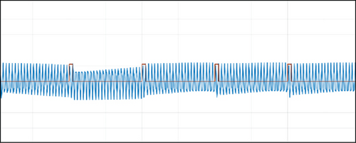
The red pulses indicate when the key is opened. In fact, when the batteries are directly connected to the energy converter, a large number of disconnections and connections will occur, disrupting the continuous process of battery charging. Now that the supercapacitor has been added to the circuit, the voltage across the battery terminals becomes significantly more stable, as it smooths out fluctuations caused by the energy converter and prevents frequent disruptions in the charging process.
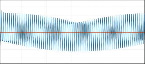
The voltage waveform across the battery terminals without a supercapacitor is shown in Figure 7, highlighting fluctuations caused by direct connection to the energy converter. As illustrated in Figure 8, integrating a supercapacitor smooths out voltage fluctuations and stabilizes the energy supply. It is clear that opening and closing the key for a brief period of time has no effect on the potential difference between the two battery ends. The input distortions will be removed once the supercapacitor is connected between the energy converter and the battery. The effectiveness of the supercapacitor in filtering input distortions is presented in Figure 9.
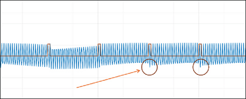
In the two cases mentioned, in the presence and absence of the supercapacitor, we checked the node lifetime twice: once with a small number of nodes and once with a large number of nodes. The first state occurs when the nodes are operating normally, and the aforementioned strategy has not yet been implemented on them.
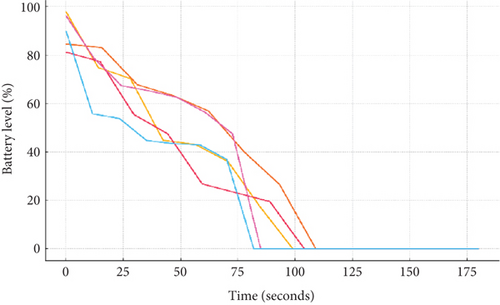
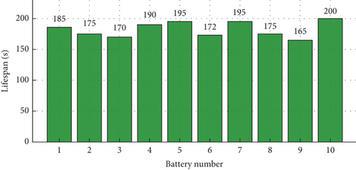
Baseline battery lifespans for five WSN nodes prior to optimization are shown in Figure 10. A comparative summary of node lifespans for 10-node scenarios is provided in Table 5.
| Number of nodes | Lifespan for dual-battery scenario | Lifespan for optimized dual battery |
|---|---|---|
| 1 | 129 | 198 |
| 2 | 152 | 180 |
| 3 | 78 | 168 |
| 4 | 200 | 200 |
| 5 | 171 | 200 |
| 6 | 182 | 169 |
| 7 | 200 | 200 |
| 8 | 92 | 181 |
| 9 | 80 | 153 |
| 10 | 200 | 200 |
| Avg | 148.4 | 184.9 |
- Note: Bold values indicate the average lifespan (in seconds) across all nodes.
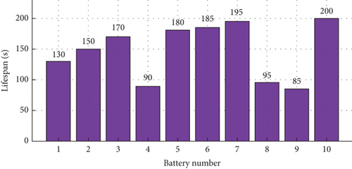
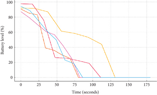
A comparison of battery lifespans for 10 nodes without optimization is provided in Figure 11. In this case, which was simulated on 5 sensor nodes, the sensors’ average working time in a short-term simulation was 148.4 s. The second case involves the simultaneous use of two batteries and a supercapacitor, which helps manage input power fluctuations more effectively and reduces strain on the batteries. The improved performance of the five-node system after implementing the proposed method is depicted in Figure 12. The enhanced battery lifespans of 10 nodes using the dual-battery and supercapacitor system are shown in Figure 13.
6. Data Analysis and Comparison
In this case, the sensors’ average working time during a short-term simulation is 184.9 s. Although the nodes work under the same and equal conditions, the length of their operation varies depending on the amount of activity they perform, the amount of data they process and send, and so on. It shows a 24.59% growth in the lifetime of WSN nodes at a scale of 10 nodes. We repeated this experiment and simulation for additional nodes.
The battery lifespan of 70 nodes under conventional configuration is illustrated in Figure 14, and as shown in Figure 15, the optimized system significantly increases battery lifespan in a large-scale deployment. In the future, energy management algorithm optimization for more extensive networks is also a promising direction to develop better performance of more complex dynamic environments. Regarding supercapacitors, new material and technology could be explored for higher energy storage capacity and lifespan, making these devices more long-term effective. Further studies must be performed to study the performance in various environmental conditions and to develop an adaptive algorithm by which the system can be tuned according to the varying environmental conditions. Additionally, testing the proposed models in larger networks with more nodes will be crucial in identifying potential limitations and challenges, guiding future improvements for more resilient and efficient WSNs.
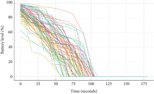
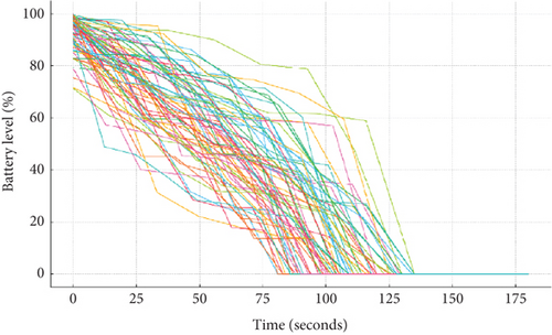
The observed improvement in battery lifespan—up to 25% compared to conventional single-battery configurations—can be attributed to two main factors. First, the dual-battery structure distributes charge and discharge cycles, reducing the DoD per cycle, which is known to significantly enhance lithium battery longevity. Second, the supercapacitor absorbs high-frequency, transient load spikes, preventing short, high-current events from being handled directly by the batteries. This mitigates voltage sag and thermal stress, both of which contribute to accelerated battery degradation.
- 1.
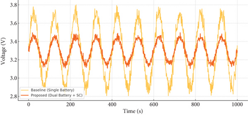
Voltage stability: The proposed system maintained a more stable voltage output throughout the simulation period compared to the single-battery baseline. As shown in Figure 16, the voltage fluctuation range was limited to ±0.15 V under variable-load conditions, whereas the baseline exhibited fluctuations up to ±0.45 V. This confirms the effectiveness of the supercapacitor in absorbing transient peaks and smoothing power delivery to the node. Figure 16 illustrates the voltage stability of the proposed system, showing significantly reduced voltage fluctuations (±0.15 V) compared to the baseline (±0.45 V) under dynamic loads.
- 2.
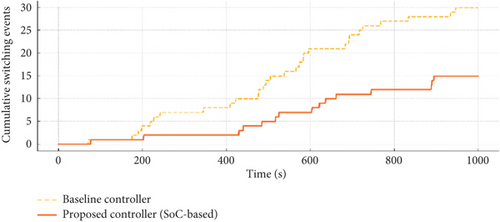
Switching frequency: The number of battery switch transitions over a 1000-s interval was measured for both control approaches. The adaptive SoC-based controller executed 12–16 switches, while a fixed threshold controller (used in [9, 10]) resulted in over 30 transitions. This reduction reflects the improved load-balancing logic of the proposed method, reducing unnecessary toggling and associated control overhead. Figure 17 presents the cumulative switching events over a 1000-s interval, demonstrating that the adaptive SoC-based controller significantly reduces switching frequency (12–16 transitions) compared to the fixed threshold method used in prior works (over 30 transitions).
7. Conclusion
This study investigated novel strategies for increasing the lifespan and reliability of WSNs by combining dual-battery systems and supercapacitors. Using supercapacitors as energy buffers reduces stress on the main batteries, lowers the DoD, and increases battery cycle life. We optimized energy management using a threshold-based switching mechanism to ensure batteries operate in stable charge ranges, reducing inefficiencies and extending component lifespans. Simulations revealed that our proposed method increased the operational lifetime of WSN nodes by about 25%, highlighting its practical benefits. This study helps to develop sustainable and resilient WSNs for applications such as environmental monitoring, smart agriculture, and industrial automation by addressing critical challenges in energy storage and power management. The integration of dual-battery systems and supercapacitors is a promising step toward long-term and cost-effective WSN deployments. Future research could concentrate on refining the proposed models for larger scale networks and investigating adaptive algorithms to improve energy management under dynamic environmental conditions.
The results of this work, while showing a significant improvement in operational lifetime and reliability for WSNs, also indicate that integrating dual-battery systems with supercapacitors could enable cost savings and increased sustainability in practical applications. This would be very useful in practical deployment, especially in applications that require either remote or energy-limited environments, such as environmental monitoring stations, smart agriculture, and industrial automation, where energy efficiency and long-term reliability are of great concern. Moreover, the proposed energy management strategy can be easily adapted for other IoT systems that require low-power operation and long battery life. Future studies would, therefore, concentrate on developing new adaptive algorithms to save energy in highly dynamic environments and finding any way to integrate WSNs with renewable sources, which will finally create a totally autonomous system.
8. Future Directions
In this regard, the future direction of research will be to advance and adapt such energy management algorithms for EH-WSNs, which could dynamically regulate with changeable environmental parameters. While the techniques of dual batteries and supercapacitors have already been effective in improving node lifetime, more refinement in power allocation is required by adopting machine learning–based and artificial intelligence–based techniques for power allocation in sensor nodes. The predictive models, based on energy-harvesting patterns and sensor power consumption, will further help in optimizing the switching mechanisms between primary and secondary storage units for efficient energy distribution without losses. Furthermore, research into new materials and technologies for supercapacitors will contribute to better energy storage capacity, lifetime, and charging efficiency, thus enhancing overall system stability. Other possible directions for research include hybrid energy-harvesting sources, like thermoelectric and piezoelectric generators, which may provide alternative energy inputs and make EH-WSNs more resilient in diverse operational environments. Another key research direction is the large-scale deployment and real-world validation of EH-WSN architectures to assess the performance of different applications, including precision agriculture, environmental monitoring, and industrial automation.
While simulations have exhibited very remarkable improvements in sensor network lifetimes, the use of practical implementations in diverse geographic and climatic regions can bring to light other opportunities for optimization. It will be important to investigate the implications of energy-harvesting variability on communication protocols, network congestion, and transmission reliability for stable network operations in unforgiving environments. Future works will also focus on the design of self-healing network architecture capable of adapting routing paths with real-time energy availability and battery health, which will make WSNs robust and adaptable. Further research directions should be targeted toward investigating the possibility of embedding blockchain-based energy management frameworks into WSNs for decentralized control in power distribution and ensuring secure and transparent energy transactions among sensor nodes. These will bring us closer to realizing fully autonomous, long-lived, and intelligent WSNs able to support critical applications with infrequent human intervention.
Conflicts of Interest
The authors declare no conflicts of interest.
Funding
No funding was received for this manuscript.
Open Research
Data Availability Statement
The data that support the findings of this study are available from the corresponding author upon reasonable request.


