Experimental Investigation and Multi-Response Optimization of Drilling and Milling Parameters for Sisal/Bamboo Fiber-Reinforced Hybrid Composites
Abstract
This study investigates the machining behavior of a sisal/bamboo fiber reinforced polyester matrix hybrid composite (10%/20%/70% weight ratio, unidirectional 0° orientation) through drilling and milling operations. Taguchi methods and Gray Relational Analysis (GRA) were employed to optimize machining parameters (spindle speed, feed rate, tool diameter, and depth of cut) while considering delamination, surface roughness (Ra), and material removal rate (MRR). ANOVA (analysis of variance) was utilized to analyze the influence of the parameters. Drilling results showed that spindle speed influenced entry delamination, while tool diameter significantly impacted exit delamination. Optimal drilling parameters (A1B3C3: 380 rpm, 0.25 mm/rev, 10 mm) minimized delamination (DFentry = 1.10, DFexit = 1.50) while maximizing MRR (19.63 mm3/min). In milling, feed rate was the dominant factor influencing both delamination and Ra. Higher feed rates led to increased delamination and Ra. Higher spindle speeds reduced Ra. The optimal milling parameters (S3F3d2: 1180 rpm, 0.06 mm/rev, 3 mm) minimized delamination (1.41) and Ra (0.17) while maximizing MRR (2548.8 mm3/min). Although feed rate showed the largest influence on MRR, none of the factors were found to be statistically significant in influencing MRR based on ANOVA. This study provided valuable insights for optimizing machining parameters to enhance performance and reduce defects in processing the biocomposite.
Summary
- •
Studied machining of sisal and bamboo fiber-reinforced polyester composite.
- •
Applied Taguchi method, Gray Relational Analysis (GRA), and ANOVA (analysis of variance) techniques.
- •
Optimized machining parameters to minimize delamination and roughness while maximizing material removal.
- •
Drilling: Optimal parameters minimized delamination and maximized material removal.
- •
Milling: Optimal Parameters reduced delamination and roughness while boosting removal rate.
1. Introduction
As an alternative to synthetic fiber reinforced polymer (FRP) composites, natural fiber reinforced, bioresourced, and sustainable composite materials are being produced in response to current environmental and economic worldwide concerns [1–7]. Benefits compared to synthetic fibers like glass, aramid, carbon, and steel fibers, natural fiber reinforce polymer composites (NFRPCs) are less dense, more readily available, completely biodegradable, renewable, and inexpensive [8–13]. Among many natural fibers like kenaf, jute, oil palm, cotton, flax, banana, and hemp, sisal is gaining attention due to its abundance, affordability, good thermal and acoustic insulation properties, high toughness, abrasion resistance, and comparable mechanical properties to hemp, banana, and jute. Sisal accounts for roughly two-thirds of global hard fiber production. Its primary application lies in agricultural twine, consuming about three-quarters of all sisal produced [14, 15]. Sisal plant thrives in harsh conditions, flourishing in drought-stricken areas and a wide range of soils and climates [16, 17]. Sisal fiber needs to be chemically treated to improve its mechanical and moisture resistance before it can be used in composites. These chemical processes eliminate the hemicellulose and lignin found in the natural fiber, which enhances the interfacial bonding between the hydrophilic natural fiber and the hydrophobic polymer matrix [18, 19]. Currently, sisal fiber-reinforced epoxy composites are being investigated as potential replacement materials for electrical automotive applications through heat and alkali treatments [20].
Bamboo fiber shares several characteristics with hardwood fiber. Compared to hardwood, bamboo fiber is longer-lasting and more environmentally friendly. While the mechanical characteristics of bamboo fibers approach those of synthetic fibers, their mechanical strength is significantly influenced by factors, such as fiber orientation, length, and the extent of treatment [21]. Despite exhibiting superior mechanical performance compared to most natural fibers, bamboo fibers tend to be more brittle than others due to the presence of higher lignin content, which surrounds and stiffens the fibers [21, 22]. Therefore, hybridizing bamboo is crucial for overcoming its inherent weaknesses and expanding its applicability in various green applications [23, 24]. Mosisa and Batu [25] studied bamboo-sisal fiber reinforced epoxy composites. They found that a 20/15% sisal-to-bamboo ratio exhibited the highest compression strength, while a 15/20% ratio demonstrated the best hardness. Mamo [26] investigated the mechanical properties of Sisal/Bamboo/Polyester composites and demonstrated that hybridization significantly enhanced their overall performance. A 10/20/70 weight ratio of Sisal/Bamboo/Polyester exhibited superior performance compared to composites utilizing individual fibers. The combined fibers demonstrate enhanced performance due to their interaction, effectively overcoming the individual limitations of each component. This underscores the importance of hybridization in improving the properties of bio-based materials.
While the hybridization of sisal and bamboo fibers enhanced the mechanical performance of the resulting composites, machining remains a critical step in shaping and ensuring the structural integrity of these materials. Machining of FRP composites, regardless of whether they incorporate natural or synthetic fibers, presents unique challenges. Unlike conventional materials, these composites exhibit distinct machining behaviors, leading to issues, such as high tool wear, surface defects, and poor processing efficiency. These challenges can significantly hinder the widespread application of sisal-bamboo hybrid composites [27]. Furthermore, the inherent nonhomogeneity and anisotropic nature of these materials intensifies the issue, frequently resulting in serious material defects, such as matrix cracking, delamination damage, matrix burning, fiber breakage, fiber pull-out, and fiber-matrix deboning [28]. Drilling holes in fiber-reinforced polymer composites is an essential and unavoidable machining step in the assembly process [29, 30]. Process variables (feed, cutting speed, and tool geometry) are crucial in determining the quality of the hole and the rate of removal of natural fiber-reinforced polymer (NFRP) composites [30–32]. Delamination is primarily characterized as a key failure mode in fibrous composites, where the layers or laminates separate along their interfaces. It can appear as a crack between adjacent plies, often occurring as an interface crack between two anisotropic and heterogeneous materials [33]. Numerous studies have identified that higher feed rates lead to increased delamination, while greater cutting speeds tend to decrease it [34, 35]. High speed steel (HSS) drills are widely used due to their accessibility, low cost, and exceptional toughness, which makes them the preferred choice for tooling materials [36, 37]. Material removal rate (MRR), the amount of material removed per unit time, is also a frequent focus in many machining studies [38]. The MRR is increased as the speed of the machining process is increased [39].
Milling is also a crucial machining process widely employed to create precise pockets, slots and high dimensional accuracy. Spindle speed, feed rate, and depth of cut are the three main independent factors that have a significant influence on determining the quality of the milled surface, such as delamination and surface roughness [32, 40]. A milling cutter with more flutes, such as an end milling cutter, can be used to provide a smoother milled surface when milling completely biodegradable green composites [41]. Surface roughness (Ra) is significantly affected by the cutting parameters, specifically the feed rate and spindle speed. Ra generally increased with increasing feed rate and decreased with increasing spindle speed [42]. Design of experiments (DOE), specifically the Taguchi method, is employed to assess the influence of input parameters on performance characteristics [43]. This method utilizes a loss function to quantify the deviation between the desired and actual experimental outcomes. Furthermore, this loss function is transformed into a signal-to-noise (S/N) ratio, a metric that provides a standardized measure of pserformance consistency [44].
Treatments and hybridization techniques significantly enhanced the mechanical and water resistance properties of sisal and bamboo fibers within the composite matrix, thereby broadening their application potential [45–47]. However, research on the drilling and milling behavior of biodegradable green composites remains in its early stages. The machining characteristics of bamboo and sisal fiber-reinforced hybrid composites have not yet been extensively studied. This study experimentally investigates the drilling and milling behavior of sisal/bamboo fiber-reinforced polyester matrix hybrid composites. The composites were fabricated using the hand lay up method, incorporating a polyester matrix with optimal proportions of bamboo and sisal fibers. Taguchi’s analysis was employed to optimize drilling parameters (spindle speed, feed rate, and tool diameter) with the objectives of minimizing the delamination factor (DF) and maximizing the MRR. Similarly, for milling, Taguchi’s analysis was used to optimize parameters (feed rate, spindle speed, and depth of cut) with the objectives of minimizing delamination and Ra while maximizing MRR. Furthermore, GRA was employed for multi-response optimization. Analysis of variance (ANOVA) was conducted to determine the relative significance of each input parameter.
2. Materials and Experimental Method
2.1. Materials
Sisal plant leaves were sourced from the outskirts of Mekelle city, Tigray, Ethiopia. Bamboo fiber was provided by ADAL Industrial plc in Addis Ababa, Ethiopia. The densities of sisal and bamboo fibers are 1.33 and 1.1 g/cm3, respectively. Unidirectional (0°) orientation was used for both fibers, and both were cut to a 30 cm length for the hybrid composite fabrication. Polyester resin, with a density of 1.2 g/cm3, and its hardener, sourced from local composite manufacturers, served as the matrix material. Sodium hydroxide, procured from local suppliers, was utilized for the chemical treatment of both sisal and bamboo fibers.
2.2. Alkali Treatment
In order to improve the interfacial adhesion between the resin and the fiber, natural fibers are routinely treated [11]. Thus, the sisal and bamboo fibers were subjected to an alkaline treatment, which is the most cost-effective method [11]. The fibers were immersed in a 6% by weight aqueous solution of sodium hydroxide for 3 h, following the study by Yahaya et al. [48] Subsequently, the fibers were thoroughly washed with water to remove any residual NaOH and then allowed to air-dry at room temperature for 72 h.
2.3. Hybrid Composite Fabrication
Hybrid composites were fabricated using a combination of hand layup and compression molding techniques. Polyester resin, mixed with 2% hardener according to manufacturer instructions, was used to impregnate the fiber layers. Unidirectional bamboo and sisal fibers, oriented at 0°, were placed in a flat mold and impregnated with the resin. This unidirectional arrangement (0°) demonstrated superior mechanical properties compared to cross-ply (0°/90°) configurations [47, 49]. The resin-saturated laminates were then compressed using a cylindrical wooden rod to ensure complete resin penetration, remove air bubbles, and eliminate excess resin. A 10/20/70 weight percentage of Sisal/Bamboo/Polyester was selected for this study based on its superior strength compared to other ratios as reported in previous research [26]. The laminate configuration employed two layers of bamboo sandwiching a single layer of sisal, taking advantage of bamboo’s superior mechanical and water resistance properties to enhance the overall composite performance [50, 51]. The mold was closed and cured under a constant 2 kN load for 24 h at room temperature.
2.4. Drilling and Milling Techniques
After the development of sisal/bamboo fiber reinforced hybrid composite, samples were cut into the required dimensions of 40 mm × 250 mm × 7.5 mm for drilling operation and 100 mm × 100 mm × 7.5 mm for milling operation. For both operations, nine experiments were prepared. HSS drill bits with three different diameters were used to conduct the drilling operations, with five trials performed for each drill bit. Milling experiments were conducted using a four-fluted HSS end mill with a diameter of 12 mm on the developed hybrid composite samples. All drilling and milling operations were conducted dry using conventional machines available at Mesfin Industrial Engineering (MIE) in Mekelle, Ethiopia. At least five tests were performed for each experiment, and all tests were conducted under ambient conditions.
2.5. Delamination of Drilled Holes
2.6. MRR of Drilled Hole
2.7. Delamination of Milled Surface
2.8. Ra of Milled Surface
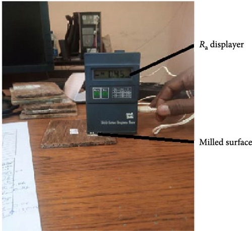
Ra significantly impacts both the production cost and the performance of machined components. In this study, the Ra of the milled hybrid composite material was characterized according to ASTM E429. Measurements were conducted using a TR100 Ra tester, as illustrated in Figure 1.
2.9. MRR of Milled Surface
2.10. Taguchi Method and DOE
Testing and statistical analysis were conducted using the L9 orthogonal array [56]. Taguchi analysis was employed to optimize the results by identifying the optimal combination of input factors [43, 57]. This method aims to achieve the best outcome with the minimum number of experiments [58]. The examination of the S/N ratio can be categorized into three types of quality characteristics: higher-the-better, nominal-the-best, and lower-the-better [44]. The process parameters considered in this study are spindle speed, feed rate, and tool diameter for drilling operations and spindle speed, feed rate, and depth of cut for milling operations, as shown in Tables 1 and 2. The milling process parameters (feed rates, depths of cut, and spindle speeds) and their respective ranges were selected based on existing research, ensuring a suitable optimization window. The initial values chosen for optimization, which fall within the optimal ranges reported in previous studies [59–62], were adopted as starting points. Similarly, the initial drilling parameters were selected to align with optimal ranges found in previous literature [52, 63–65]. This approach allows us to utilize established research to efficiently explore and further optimize these parameters for this specific composite material.
| Factors (process parameters) | Symbol | Low level | Middle level | High level | |
|---|---|---|---|---|---|
| — | Spindle speed (rpm) | A | 380 | 660 | 1220 |
| — | Feed rate (mm/rev) | B | 0.10 | 0.16 | 0.25 |
| — | Tool diameter (mm) | C | 6 | 8 | 10 |
| Numerical notation of levels | — | — | 1 | 2 | 3 |
| Factors (process parameters) | Symbol | Low level | Middle level | High level | |
|---|---|---|---|---|---|
| — | Spindle speed (rpm) | S | 475 | 750 | 1180 |
| — | Feed rate (mm/rev) | F | 0.02 | 0.04 | 0.06 |
| — | Depth of cut (mm) | D | 2 | 3 | 4 |
| Numerical notation of levels | — | — | 1 | 2 | 3 |
| Experimental run | Process parameters | ||
|---|---|---|---|
| A | B | C | |
| 1 | 1 | 1 | 1 |
| 2 | 1 | 2 | 2 |
| 3 | 1 | 3 | 3 |
| 4 | 2 | 1 | 2 |
| 5 | 2 | 2 | 3 |
| 6 | 2 | 3 | 1 |
| 7 | 3 | 1 | 3 |
| 8 | 3 | 2 | 1 |
| 9 | 3 | 3 | 2 |
| Experimental run | Process parameters | ||
|---|---|---|---|
| S | F | D | |
| 1 | 1 | 1 | 1 |
| 2 | 1 | 2 | 2 |
| 3 | 1 | 3 | 3 |
| 4 | 2 | 1 | 2 |
| 5 | 2 | 2 | 3 |
| 6 | 2 | 3 | 1 |
| 7 | 3 | 1 | 3 |
| 8 | 3 | 2 | 1 |
| 9 | 3 | 3 | 2 |
2.11. Multi-Response Optimization Using Gray Relational Analysis(GRA)
The Taguchi technique, while effective, does not inherently provide a comprehensive solution for finding effective parameters for multiple objective functions simultaneously. Therefore, GRA is a suitable approach for optimizing multiple objective functions by considering the relative importance of various quality characteristics (responses) [66–68]. In this study, GRA was employed in conjunction with the Taguchi method to optimize multiple responses, aiming to minimize DF and Ra while maximizing MRR. For GRA, the ’smaller-the-better’ equation was applied for DF and Ra, while the ’higher-the-better’ equation was used for MRR, as described in Equations (7) and (8), respectively.
GRA consists of the following steps:
Step 1: Gray relational generation
The initial stage in GRA involves normalizing the experimental data based on the performance response type. If the target value is maximum, the ’higher-the-better’ equation is used. Conversely, if the target value is minimum, the ’smaller-the-better’ equation is applied.
Step 2: Gray relational coefficient
Step 4: Gray relational ordering
In this step, the ranking of different parameter combinations is performed based on their overall performance across sssmultiple objectives.
2.12. ANOVA
ANOVA was performed using MINITAB software. This analysis, which employs a computational technique, aims to estimate each control factor’s proportional contribution to the overall response. The contributions are presented as percentages. In statistical analyses, a significance level of α = 0.05 is generally used, corresponding to a 95% confidence level [58, 69, 70]. In this study, ANOVA was utilized to analyze the influence of parameters (spindle speed, feed rate, tool diameter, and depth of cut) on DF and MRR for drilling operations, as well as on DF, Ra, and MRR for milling operations.
3. Results and Discussion
3.1. Taguchi Analysis
3.1.1. Delamination of Drilled Holes
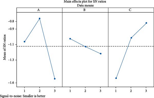
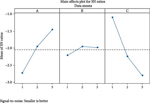
The optimal conditions for each response are indicated by the design parameter levels with the highest S/N ratios. The optimal conditions for minimizing delamination at entry are spindle speed of 660 rpm, feed rate of 0.16 mm/min, and tool diameter of 10 mm, with a minimal value of 1.050, as depicted in Figure 2a. The optimal conditions for minimizing delamination at exit are spindle speed of 1220 rpm, feed rate of 0.16 mm/min, and tool diameter of 6 mm, with the minimal value of 1.06, as shown in Figure 2b. The optimal drilling parameters for minimizing delamination at the exit in this study are consistent with those reported by Rajmohan et al. [32] (0.1 mm/rev feed rate, 1200 rev/min spindle speed, 3 mm drill diameter) for Sisal-banana composites. As the diameter of the drill bit increased (from 6–10 mm), the DF at entry decreased. This may be attributed to an increase in thrust force developed on the drill bit during drilling operations. Therefore, a slightly larger tool diameter might be preferable for minimizing delamination at entry [71]. Moreover, feed rate is observed to decrease delamination while increasing the tool diameter while keeping the spindle speed constant. However, higher feed rates lead to increased delamination damage at the exit. This increase in delamination is primarily attributed to the higher torque exerted on the composite material by increased feed rates and larger tool diameters [72]. Consistent with previous research on natural fiber reinforced composites (NRFCs)[32, 34], the results indicate that drilling-induced delamination increases with feed rate but decreases with higher spindle speeds, primarily attributed to the increased thrust force during drilling. Furthermore, an increase in spindle speed results in reduced delamination, as shown in Table 5. The lowest delamination damage at exit was observed at higher speed, medium feed, and lower tool diameter. In most of the experiments, delamination at the exit was observed to be more severe than at entry. This can be attributed to a combination of factors. As the drill bit approaches the exit surface, the material experiences a sudden release of constraint, potentially leading to localized stresses. Additionally, chip formation and removal become more complex at the exit, potentially leading to increased stresses and a higher risk of delamination.
| Run | Response (target functions) | S/N ratio for various responses | ||||
|---|---|---|---|---|---|---|
| DFentry | DFexit | MRR (mm3 /min) | DFentry | DFexit | MRR | |
| 1 | 1.167 | 1.25 | 2.82 | −1.341 | −1.938 | 9.005 |
| 2 | 1.125 | 1.37 | 8.04 | −1.023 | −2.734 | 18.105 |
| 3 | 1.10 | 1.50 | 19.63 | −0.827 | −3.521 | 25.858 |
| 4 | 1.062 | 1.32 | 5.02 | −0.522 | −2.411 | 14.014 |
| 5 | 1.050 | 1.35 | 12.56 | −0.423 | −2.606 | 21.978 |
| 6 | 1.167 | 1.10 | 7.06 | −1.341 | −0.827 | 16.976 |
| 7 | 1.150 | 1.30 | 7.85 | −1.213 | −2.278 | 17.897 |
| 8 | 1.250 | 1.06 | 4.52 | −1.938 | −0.506 | 13.102 |
| 9 | 1.187 | 1.20 | 12.56 | −1.489 | −1.583 | 21.979 |
3.1.2. MRR of Drilled Holes
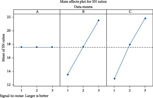
As presented in Table 5, MRR of the drilled hole is observed to depend primarily on the drill bit diameter, spindle speed, and feed rate. MRR increases as both the diameter of the drill bit and the feed rate increase. Since maximizing the MRR is the main objective of this analysis, this study is concentrated on the “larger-the-better” quality characteristic based on the S/N ratio classification. Therefore, spindle speed of 380 rpm, 0.25 mm/min feed rate, and 10 mm tool diameter are the optimal conditions for maximum MRR value of 19.63 mm3/min, as shown in Figure 3. From this study, it was observed that the MRR of the drilling process increases as the feed rate and tool diameter are increased.
3.1.3. Delamination of Milled Surface
For delamination, the “lower-the-better” quality characteristic was used based on the S/N ratio classification since the primary objective of the analysis is to minimize the DF of the milled surface of the bamboo/sisal fiber reinforced polyester matrix hybrid composite. The system’s optimal conditions are indicated by the design parameter levels with the highest S/N ratio. Therefore, spindle speed of 475 rpm, feed rate of 0.02 mm/rev, and depth of cut of 3 mm are the process parameters that are found to yield the best values for minimum DF of the milled surface, as depicted in Figure 4. DF values of the milled sisal/bamboo fiber reinforced hybrid composite increased as spindle speed increased. This may be attributed to progressive tool wear, which can cause fibers to be pushed outside at the top edge of the slot [73]. Similar investigations were reported in previous research [40]. Similarly, delamination damage of the milled surface of the sisal/bamboo fiber reinforced composite is observed to decrease as the feed rate decreases, as shown in Table 6.
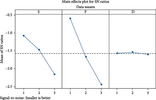
| Run | Response (target functions) | S/N ratio for various responses | ||||
|---|---|---|---|---|---|---|
| DF | Ra (µm) | MRR (mm3/min) | DF | Ra | MRR | |
| 1 | 1.01 | 0.063 | 228 | −0.08643 | 24.01319 | 47.1587 |
| 2 | 1.15 | 0.21 | 684 | −1.21396 | 13.55561 | 56.70112 |
| 3 | 1.25 | 0.34 | 1368 | −1.9382 | 9.370422 | 62.72172 |
| 4 | 1.05 | 0.04 | 540 | −0.42379 | 27.9588 | 54.64788 |
| 5 | 1.2 | 0.15 | 1440 | −1.58362 | 16.47817 | 63.16725 |
| 6 | 1.32 | 0.22 | 1080 | −2.41148 | 13.15155 | 60.66848 |
| 7 | 1.16 | 0.015 | 1132.8 | −1.28916 | 36.47817 | 61.08306 |
| 8 | 1.29 | 0.11 | 1132.8 | −2.21179 | 19.17215 | 61.08306 |
| 9 | 1.41 | 0.17 | 2548.8 | −2.98438 | 15.39102 | 68.12672 |
3.1.4. Ra of Milled Surface
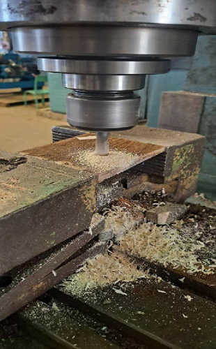
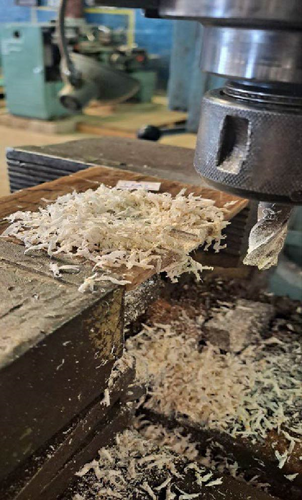
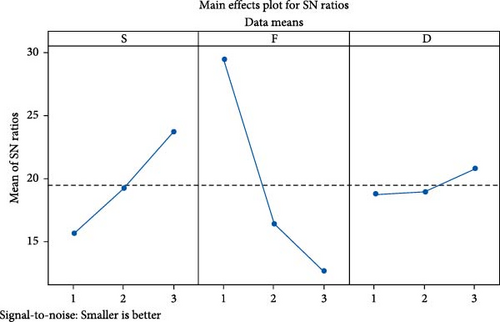
Optimal Ra conditions, determined by the design parameter levels with the highest S/N) ratio, were achieved at a spindle speed of 1180 rpm, a feed rate of 0.02 mm/rev, and a depth of cut of 4 mm. These parameters yielded a minimum roughness of 0.015 μm, as shown in Figure 5. Feed rate significantly influences chip formation, with higher feed rates resulting in coarser, larger chips, and consequently, increased Ra. Conversely, lower feed rates produced finer chips and improved surface finishes for the sisal/bamboo fiber reinforced hybrid composites. This relationship is attributed to the abrasive action between the larger chips and the machined surface at higher feed rates [73]. As illustrated in Figure 6, increasing feed rate leads to thicker chip formation, as more material is forced into the cutter per unit time, directly correlating with increased Ra. The abrasive action of these thicker chips contributes to the observed roughness. Conversely, thinner chips formed at lower feed rates result in better surface finishes. Additionally, experimental observations revealed a decrease in Ra at higher spindle speeds. This reduction is likely due to thermal softening of the polyester matrix, a consequence of increased heat generation. Elevated stress and temperatures at higher speeds induce thermal deformation (softening) of the matrix [73]. When NFRCs are machined at higher spindle speeds, heat is generated at the cutting zone [37]. In polymer matrix composites, high temperatures cause matrix softening and differential thermal expansion between the matrix and fibers, generating interfacial stress and potential debonding. At high spindle speeds, rapid chip shear deformation results in thinner, more fragmented chips, which contribute less to Ra [74]. Conversely, lower spindle speeds lead to increased chip thickness, subsequently increasing the roughness of the milled surface.
3.1.5. MRR of Milled Surface
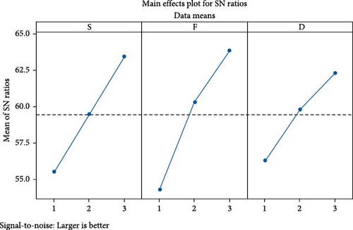
For MRR, the “larger-the-better” quality characteristic was employed based on the S/N ratio classification, as the primary goal of the target function is to maximize MRR. Therefore, as seen in Figure 7, the optimum conditions for maximum MRR are spindle speed of 1180 rpm, feed rate of 0.06 mm/rev, and depth of cut of 4 mm. As mentioned in Equation (4), MRR is directly proportional to feed rate and depth of cut. This is supported by the experimental observations, which clearly demonstrate an increase in MRR values with increases in both feed rate and depth of cut as shown in Table 6.
3.2. Multi-Response Optimization With GRA
3.2.1. GRA for Drilling Optimization
The primary focus of this investigation was to minimize the DF and maximize the MRR. To achieve this, the “smaller-the-better” approach was applied to reduce DF, while the “larger-the-better” approach was applied to maximize MRR within the framework of Taguchi-based GRA. The gray relational coefficient for the normalized data was determined using Equation (9), and subsequently, the gray relational grades (GRGs) were obtained through Equation (13). Both the grades and their respective rankings were utilized to optimize the multi-response parameters. A higher GRG value indicates a stronger correlation between the experimental and normalized values, signifying a closer proximity to the optimal conditions. From Table 7, the largest GRG value (0.801) corresponds to the optimal conditions for minimizing DF and maximizing MRR in drilling a hole in the bamboo/sisal fiber reinforced polyester matrix hybrid composite. The best process parameter setting for optimizing multiple performance characteristics was identified as A1B3C3, which translates to a spindle speed of 380 rpm, a feed rate of 0.25 mm/rev, and a tool diameter of 10 mm.
| Experiment number | Normalized values of S/N ratios | Gray relational coefficient | GRG | Order | ||||
|---|---|---|---|---|---|---|---|---|
| DFentry | DFexit | MRR | DFentry | DFexit | MRR | |||
| 1 | 0.605 | 0.474 | 0 | 0.560 | 0.487 | 0.333 | 0.460 | 8 |
| 2 | 0.396 | 0.738 | 0.540 | 0.452 | 0.657 | 0.520 | 0.543 | 5 |
| 3 | 0.267 | 1 | 1 | 0.405 | 1 | 1 | 0.801 | 1 |
| 4 | 0.065 | 0.631 | 0.297 | 0.348 | 0.575 | 0.415 | 0.446 | 9 |
| 5 | 0 | 0.696 | 0.769 | 0.333 | 0.622 | 0.684 | 0.546 | 4 |
| 6 | 0.605 | 0.106 | 0.472 | 0.560 | 0.358 | 0.486 | 0.468 | 7 |
| 7 | 0.521 | 0.587 | 0.527 | 0.510 | 0.548 | 0.514 | 0.524 | 6 |
| 8 | 1 | 0 | 0.243 | 1 | 0.333 | 0.397 | 0.577 | 3 |
| 9 | 0.703 | 0.357 | 0.770 | 0.627 | 0.437 | 0.684 | 0.583 | 2 |
3.2.2. GRA for Milling Optimization
In milling operations, the primary objective is to minimize the DF and arithmetic average roughness (Ra) while simultaneously maximizing the MRR. To achieve this, the “smaller-the-better” approach was applied to reduce DF and Ra, while the “larger-the-better” approach was applied to maximize MRR within the framework of Taguchi-based GRA. The gray relational coefficient for the normalized data was determined using Equation (9), and subsequently, the GRGs were obtained through Equation (13). Both the GRG values and their corresponding rankings were utilized to determine the optimal parameter combination. A higher GRG value indicates a stronger correlation between the experimental and normalized values, signifying a closer proximity to the optimal conditions. According to Table 8, the highest GRG value of 0.897 was identified. This value corresponds to the optimal condition for achieving minimal DF and Ra while simultaneously maximizing MRR in the milling of the bamboo/sisal fiber reinforced polyester matrix hybrid composites. The optimal process parameter setting was determined to be S3F3d2, corresponding to a spindle speed of 1180 rpm, a feed rate of 0.06 mm/rev, and a depth of cut of 3 mm.
| Experiment number | Normalized value of S/N ratios | Gray relational coefficient | GRG | Order | ||||
|---|---|---|---|---|---|---|---|---|
| DF | Ra | MRR | DF | Ra | MRR | |||
| 1 | 0 | 0.460 | 0 | 0.333 | 0.480 | 0.333 | 0.382 | 9 |
| 2 | 0.389 | 0.845 | 0.455 | 0.450 | 0.764 | 0.478 | 0.564 | 6 |
| 3 | 0.638 | 1 | 0.742 | 0.580 | 1 | 0.660 | 0.746 | 2 |
| 4 | 0.116 | 0.314 | 0.357 | 0.361 | 0.421 | 0.437 | 0.406 | 8 |
| 5 | 0.516 | 0.737 | 0.763 | 0.508 | 0.655 | 0.678 | 0.614 | 4 |
| 6 | 0.802 | 0.860 | 0.644 | 0.716 | 0.781 | 0.584 | 0.694 | 3 |
| 7 | 0.415 | 0 | 0.664 | 0.460 | 0.333 | 0.598 | 0.464 | 7 |
| 8 | 0.733 | 0.638 | 0.664 | 0.652 | 0.580 | 0.598 | 0.610 | 5 |
| 9 | 1 | 0.778 | 1 | 1 | 0.692 | 1 | 0.897 | 1 |
3.3. ANOVA Analysis
3.3.1. Delamination of Drilled Holes
Tables 9 and 10 present ANOVA results for delamination on entry and exit, respectively, during drilling of a sisal/bamboo fiber-reinforced hybrid composite. For entry delamination (DF on entry), spindle speed contributed most to variation (50.77%), followed by tool diameter (45.40%) and feed rate (2.99%). The highest F-value (60.49) for spindle speed suggests a significant effect. For exit delamination (DF on exit), tool diameter contributed most (62.24%), followed by spindle speed (35.35%) and feed rate (0.99%). The highest F-value here (43.59) for tool diameter also suggests a significant effect. However, in both cases, feed rate was statistically insignificant (p > 0.05) in influencing delamination at entry and exit.
| Source | DF | Adj SS | Adj MS | Contribution (%) | F-value | p-Value |
|---|---|---|---|---|---|---|
| A | 2 | 0.016184 | 0.008092 | 50.77 | 60.49 | 0.016 |
| B | 2 | 0.000954 | 0.000477 | 2.99 | 3.56 | 0.219 |
| C | 2 | 0.014470 | 0.007235 | 45.40 | 54.08 | 0.018 |
| Error | 2 | 0.000268 | 0.000134 | 18.07 | — | — |
| Total | 8 | 0.031876 | — | 100 | — | — |
| Source | DF | Adj SS | Adj MS | Contribution (%) | F-value | p-Value |
|---|---|---|---|---|---|---|
| A | 2 | 0.053356 | 0.026678 | 35.35 | 24.75 | 0.039 |
| B | 2 | 0.001489 | 0.000744 | 0.99 | 0.69 | 0.591 |
| C | 2 | 0.093956 | 0.046978 | 62.24 | 43.59 | 0.022 |
| Error | 2 | 0.002156 | 0.001078 | 1.43 | — | — |
| Total | 8 | 0.150956 | — | 100 | — | — |
3.3.2. MRR of Drilled Holes
The ANOVA results in Table 11 show the influence of tool diameter, feed rate, and spindle speed on the MRR during drilling of the sisal/bamboo fiber-reinforced hybrid composite. Tool diameter contributed the most to MRR variation (50.44%), followed by feed rate (42.93%) and spindle speed (3.32%). Although the high F-value (15.10) for tool diameter suggests a significant effect, all p-values exceeded 0.05, indicating that none of the factors significantly affected MRR.
| Source | DF | Adj SS | Adj MS | Contribution (%) | F-value | p-Value |
|---|---|---|---|---|---|---|
| A | 2 | 7.247 | 3.623 | 3.32 | 1.00 | 0.500 |
| B | 2 | 93.739 | 46.87 | 42.93 | 12.96 | 0.072 |
| C | 2 | 110.137 | 55.069 | 50.44 | 15.23 | 0.062 |
| Error | 2 | 7.233 | 3.646 | 3.34 | — | — |
| Total | 8 | 218.391 | — | 100 | — | — |
3.3.3. Delamination of Milled Surface
Table 12 presents the results of the ANOVA analysis concerning the DF of the sisal/bamboo fiber reinforced hybrid composite after milling operations. The analysis revealed that feed rate had the most significant influence on delamination, contributing 73.41% to the total variation. Spindle speed contributed 26.35%, while the contribution of depth of cut was negligible at 0.02%. This negligible influence of depth of cut is further supported by the p-value of 0.929, which is greater than the significance level of 0.05, indicating that depth of cut does not significantly affect delamination. The largest F-value of 334.46 for feed rate indicates that variations in feed rate have a statistically significant impact on the DF.
| Source | DF | Adj SS | Adj MS | Contribution (%) | F-value | p-Value |
|---|---|---|---|---|---|---|
| S | 2 | 0.034689 | 0.017344 | 26.35 | 120.08 | 0.008 |
| F | 2 | 0.096622 | 0.04831 | 73.41 | 334.46 | 0.003 |
| d | 2 | 0.000022 | 0.000011 | 0.02 | 0.08 | 0.929 |
| Error | 2 | 0.000289 | 0.000144 | 0.22 | — | — |
| Total | 8 | 0.131214 | — | 100 | — | — |
3.3.4. Ra of Milled Surface
Table 13 presents the results of the ANOVA analysis related to the Ra of the sisal/bamboo fiber reinforced hybrid composite. The analysis revealed that feed rate had the most significant influence on Ra, contributing 74.54% to the total variation. Spindle speed contributed 20.48%, and depth of cut contributed 2.7%. The largest F-value of 32.69 for feed rate indicates that variations in feed rate have a statistically significant impact on Ra. However, the ANOVA results showed that depth of cut and spindle speed were statistically insignificant in influencing Ra (p > 0.05).
| Source | DF | Adj SS | Adj MS | Contribution (%) | F-value | p-Value |
|---|---|---|---|---|---|---|
| S | 2 | 0.017284 | 0.008642 | 20.48 | 8.98 | 0.100 |
| F | 2 | 0.062894 | 0.031447 | 74.54 | 32.69 | 0.030 |
| D | 2 | 0.002278 | 0.001139 | 2.70 | 1.18 | 0.458 |
| Error | 2 | 0.001924 | 0.000962 | 2.28 | — | — |
| Total | 8 | 0.084380 | — | 100 | — | — |
3.3.5. MRR of Milled Surface
The significance and percentage contribution of each factor (feed rate, spindle speed, and depth of cut) to the MRR during milling operations on the sisal/bamboo fiber-reinforced hybrid composite were evaluated using ANOVA (Table 14). Feed rate had the highest percentage contribution to MRR (45.50%), followed by spindle speed (31.83%), and depth of cut (12.76%). While feed rate showed a high F-value of 4.59, suggesting a potential significant effect on MRR, the ANOVA results indicated that none of the factors were statistically significant (p > 0.05 for all factors).
| Source | DF | Adj SS | Adj MS | Contribution (%) | F-value | p-Value |
|---|---|---|---|---|---|---|
| S | 2 | 1,123,278 | 561,639 | 31.83 | 3.21 | 0.237 |
| F | 2 | 1,605,728 | 802,864 | 45.50 | 4.59 | 0.179 |
| D | 2 | 450,272 | 225,136 | 12.76 | 1.29 | 0.437 |
| Error | 2 | 349,568 | 174,784 | 9.91 | — | — |
| Total | 8 | 3,528,846 | — | 100 | — | — |
4. Conclusion
This study investigates the drilling and milling behavior of sisal/bamboo fiber-reinforced polyester composites, utilizing Taguchi, GRA, and ANOVA to optimize process parameters and evaluate their influence on machinability. In drilling, the optimal process parameters for enhancing multiple performance characteristics are identified as a spindle speed of 600 rpm, a feed rate of 0.25 mm/min, and a tool diameter of 6 mm. This combination effectively minimizes delamination, with an entry DF of 1.167 and an exit DF of 1.10, while maximizing the MRR to 7.06 mm3/min. For milling, the best parameter setting includes a spindle speed of 750 rpm, a feed rate of 0.02 mm/rev, and a depth of cut of 3 mm. This combination minimizes delamination to 1.05 and Ra to 0.04, while achieving an MRR of 540 mm3/min. In drilling, tool diameter significantly influences exit delamination, while spindle speed primarily affects entry delamination. Higher feed rates increase delamination, particularly at the exit. The MRR is influenced by drill bit diameter, spindle speed, and feed rate, with higher feed rates and tool diameters resulting in increased MRR. However, none of these factors are statistically significant for MRR (p > 0.05). In milling, feed rate significantly affects both delamination and Ra, with higher feed rates leading to increased delamination and roughness due to coarser chips and abrasive action. Higher spindle speeds reduce Ra, likely due to the thermal softening of the matrix. Feed rate and depth of cut also influence MRR, with feed rate emerging as the dominant factor for both delamination (73.41%, F = 334.46, p < 0.05) and Ra (74.54%, F = 32.69, p < 0.05). Although feed rate contributes the most to MRR (45.50%), none of the factors, including spindle speed and depth of cut, show statistical significance in influencing MRR (p > 0.05).
Conflicts of Interest
The authors declare no conflicts of interest.
Funding
This research was supported by Mekelle University.
Acknowledgments
The authors express their gratitude to the School of Mechanical and Industrial Engineering and the School of Civil Engineering at the Ethiopian Institute of Technology Mekelle, Mekelle University, for their support in providing materials, laboratory facilities, and research funding.
Open Research
Data Availability Statement
The data that support the findings of this study are available upon request from the corresponding author. The data are not publicly available due to privacy or ethical restrictions.


