A Newmark Integral Method in Nonhomogeneous Materials With Parallel Cracks Based on Hyperbolic Heat Conduction
Abstract
The strong, transient working conditions where heat transfer involves extremely large temperature gradients, extremely large heat fluxes, and extremely short time durations of thermal disturbances may occur in engineering materials and structures. Fourier heat conduction assumes heat propagation at an infinite speed, which is not suitable for strong, transient thermal working conditions. In this paper, a Newmark integral method is presented to deal with the strong, transient heat conduction in nonhomogeneous materials based on the hyperbolic heat conduction theory. The second-order differential equation of the strong transient temperature field is discretized in the spatial and temporal domains through the finite element method (FEM) and the Newmark integral method, respectively. This allows them to be solved directly without the necessity to convert them into a pair of first-order differential equations using the Newmark integral method. Several test examples are presented to demonstrate the application of the current method. Firstly, the stability of the Newmark integral method is analyzed to ensure that the numerical oscillation is suppressed in the calculation. Then the time-related temperature field of functionally graded material (FGM) plate under strong transient thermal shock is analyzed. Finally, the thermal stress intensity factors (TSIFs) in an FGM plate with parallel cracks are extracted after combining with interaction energy integral methods (IEIMs). The results confirm that the Newmark integral method can efficiently address the transient thermal problem and ensure stability. The temperature overshooting phenomenon and thermal wave singularity are visualized at the finite speed of heat propagation. Moreover, the numerical results agree well with analytical solutions. The current method can be well applied to the design and evaluation of thermal protective materials in extreme thermal environments.
1. Introduction
Nonhomogeneous materials such as piezoelectric materials, thermal coating materials, functionally graded materials (FGMs), and biomimetic materials have some unique, excellent properties compared to homogeneous materials. The materials are widely used in aerospace, integrated circuits, and biomedical fields. In the engineering uses of nonhomogeneous materials, working conditions often involve extreme temperatures or heat transfer at the micro-/nanotemporal or spatial scales. Under high-temperature gradients, fast heat flow [1], very low temperatures [2], and microscopic temporal and spatial scales [3], heat transfer exhibits different features than what Fourier heat conduction predicts [4]. In the case of transient, high-temperature gradients, where materials undergo sudden temperature changes in a very short temporal and spatial scale, a time delay is expected in the response to these ultra-fast heat fluxes or time-dependent temperature changes. This delay occurs because of the time required for heat propagation [5]. Thus, the Fourier heat conduction model assuming an infinite speed of heat propagation is not appropriate for dealing with the transient heat conduction process. To account for the delayed thermal response, time-dependent non-Fourier heat conduction models have been developed. Many non-Fourier heat conduction models, such as nonlocal phase-lag heat conduction, three-phase-lag heat conduction, and nonlocal C–V heat conductioncan, can be applied to the design and evaluation of the materials in thermal protection systems of internal combustion engines and key components of high-speed aircraft.
In recent years, laser, microwave, and other heat sources with extremely high frequencies and short durations have become more widely used in modern technology. Thermal fracture analysis in nonhomogeneous materials has become a popular topic based on the non-Fourier heat conduction theories [6–12]. Cattaneo [6] and Vernottee [7] proposed a hyperbolic heat conduction equation coupled to the local energy balance. Ozisik and Tzou [8] analyzed the characteristics of heat wave propagation and proved that the energy equation can be reduced to that governing the heat transport through the metal lattice in the microscopic, two-step model. Wang and Han [9] obtained the heat flux intensity factor in a two-layer composite structure with an interface crack under a transient, thermal flux. Guo et al. [10] investigated the non-Fourier effect on the thermoelastic fields in a semi-infinite ceramic medium under a heating shock. Yang et al. [11] analyzed the thermal fracture of a Griffith interface crack in an orthotropic, functionally graded coating/substrate structure based on the non-Fourier heat conduction theory. Jin and Paulino [12] obtained a first-order, analytical temperature solution for FGMs using a multilayer material model. For directly handling thermal problems of nonhomogeneous materials, methods like integral transforms and singular integral equations were typically employed for analytical solutions. Babaei and Chen [13] investigated one-dimensional, transient hyperbolic heat conduction in a functionally graded hollow cylinder, assuming power-law variations in material properties. Akbarzadeh and Chen [14] developed a heat conduction model in the FGM based on the dual-phase-lag heat conduction theory. Xue et al. [15] investigated an insulated crack in a thermoelastic half-space made of FGMs using the memory-dependent heat conduction model. Fu et al. [16] studied the non-Fourier heat conduction model in a sandwich panel containing a cracked foam core. Huang et al. [17] developed a piecewise exponential model in a nonhomogeneous coating substrate structure with the interface crack under steady thermal loading. Other researchers employed perturbation methods to obtain the transient temperature distribution of FGMs [18–20]. In most existing research, analytical results for the transient temperature have been obtained for relatively simple structures or homogeneous materials [21, 22]. However, in the case of nonhomogeneous materials, the material properties distribute arbitrarily and can be a complex function of spatial locations, and consequently, the heat conduction equation becomes nontrivial for analytical methods. Researchers have, respectively, promoted the optimization of mechanical properties of materials and numerical simulations in terms of fatigue performance [23], impact toughness [24], and computational efficiency [25]. Balci and Yalcin [26] and Yildirim et al. [27] both used finite element method (FEM) to solve the surface crack problem under thermal shock load and generated numerical results of the fracture response using transient thermomechanical analysis and displacement-related techniques, respectively. Santra and Behera [28], Santra [29], and Santra and Mohapatra [30] proposed a high-precision numerical solution system for multiclass complex, fractional order, integral partial differential equations based on the simultaneous space–time Hermite wavelet method, a hybrid numerical method that combines a higher order finite difference method (FDM) and the multidimensional Hermite wavelets, and an efficient recursive algorithm. Compared with the analytical technique, the numerical technique has been widely applied to solve problems with complex material properties and/or complex geometries in engineering applications. Rathish Kumar et al. [31] numerically investigated the thermo-hydrodynamic performance of a high-speed slider bearing conducting to a stationary pad. Su et al. [32] obtained a new, second-order, two-dimensional FEM for the parabolic-type equation with rapidly oscillating coefficients. Zhang et al. [33] developed a multiple, spatially, and temporally scaled method for simulation in periodic, nonhomogeneous materials considering the effect of non-Fourier heat conduction. Yasbolaghi and Khoei [34] developed a novel coupling technique for the analysis of temperature field problems in the continuum–atomistic multiscale framework.
Till now, numerical research on the non-Fourier heat conduction model in nonhomogeneous materials/structures under thermal shock loading is still very limited. Wang and Tian [35] obtained the time-dependent temperature distribution in a nonhomogeneous material. Wang et al. [36] developed a finite element code to dealing with the one-dimensional, transient temperature, and thermal stress based on a nonclassical heat conduction model. Zhang et al. [37] developed a numerical method for obtaining the transient temperature fields in nonhomogeneous materials with inclusions. Later, Zhang et al. [38] investigated the thermal shock resistance in FGMs. In these studies, the first-order differential equation of the temperature in the temporal domain was discretized by the backward FDM based on the Fourier heat conduction theory. However, at extremely short time scales or very small length scales where non-Fourier heat conduction applies, the FDM will heavily rely on the size of the iterative time step and mesh dimensions.
- 1.
The Newmark integral method is developed to deal with the transient, thermal response in nonhomogeneous materials.
- 2.
The temperature overshooting phenomenon and thermal wave singularity are visualized at the finite speed of heat propagation.
- 3.
The Newmark integral method can be used to solve transient, thermal fracture problems with the IEIM.
2. Thermal Conduction Equation Under Transient Thermal Loading
- 1.
This is the first-type (or Dirichlet) temperature boundary condition, where the temperature on the boundary is defined as
- 2.
This is the second-type (or Neumann) temperature boundary condition, where heat flux density on the boundary is determined by
- 3.
The third-type (or the combination of Dirichlet and Neumann) temperature boundary condition can be expressed as follows:
3. Numerical Scheme for Strong Transient Temperature
Equation (18) represents an explicit expression of temperature in terms of the corresponding values of temperature and its first- and second-order time derivatives at the previous step. After getting the values of , and , the approximation of Tn+1(x, y) can be calculated.
Newmark’s method is considered to be conditionally convergent; that is, convergence is guaranteed only for a specific, finite range of step sizes. If 2β − γ ≥ 0 is satisfied, the Newmark integral method is unconditionally stable. Several typical applications include the following: the explicit central difference scheme (γ = 1/2, β = 0), stable when ωminΔt ≤ 2 (ωmin is the minimum natural vibration period of the structure); the average acceleration method (γ = 1/2, β = 1/4), which offers unconditional stability; and the linear acceleration method (γ = 1/2, β = 1/6), known for its conditional stability.
4. Numerical Examples and Discussions
Several test examples with nonhomogeneous material plates are presented in this section to illustrate the feasibility of this numerical technique. A plane strain state is assumed. In other word, all variables and material properties are functions of x-coordinate and independent of z-coordinate.
4.1. Verification
4.1.1. Verification of the Accuracy
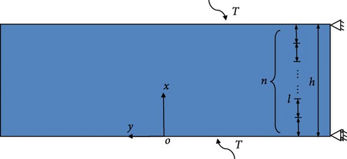
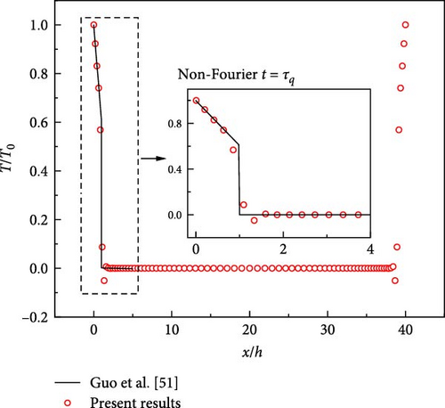
The thermomechanical properties of the material are given as τq(x) = 0.625, c(x) = ρ(x) = λ(x) = 1, h = 40l, where and κ = λ/cρ, and κ is thermal diffusivity. Figure 2a shows the results of the proposed method compared to the analytical solution given by Guo et al. [51]. Our results agree well with the analytical solutions, demonstrating that the current method is valid for the transient thermal response based on hyperbolic heat conduction.
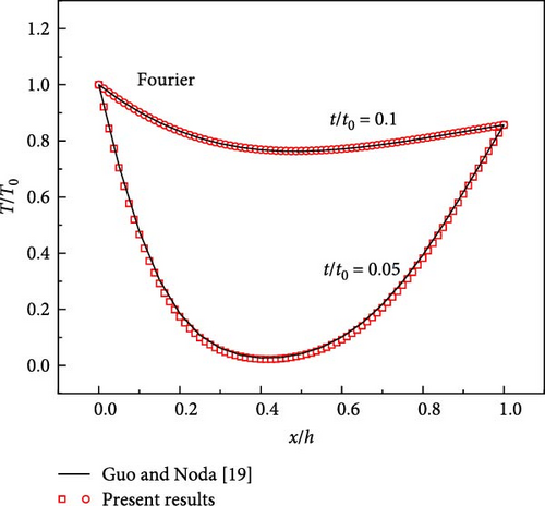
The mechanical condition is the same as those in Equations (23)–(25).
The results are depicted in Figure 2b, which also shows great agreement with the analytical solutions of Zhang et al. [20]. With those results, we are confident that the proposed method works well for the temperature response to heat transfer of both Fourier heat conduction and hyperbolic heat conduction.
4.1.2. The Stability of the Newmark Integral Method
Figure 3 displays the numerical results of temperature distribution in the specimen from the current method with different values of γ. It can be observed that the numerical results present fictitious oscillations of temperature near the upper and lower surfaces. The variation of transient temperature exhibits severe oscillations when using the average acceleration method (γ = 0.50). However, the oscillations can be greatly reduced when γ = 0.65.
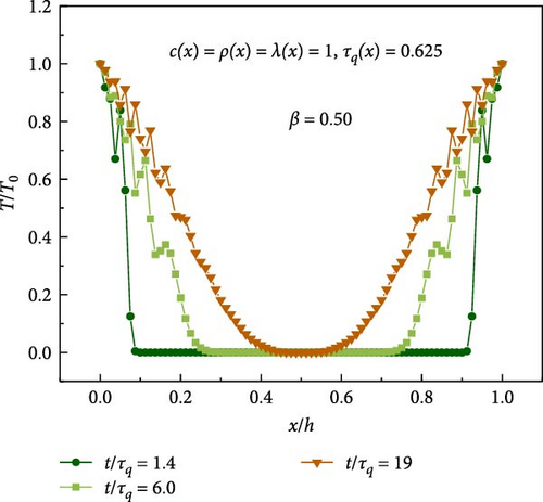
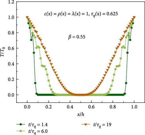
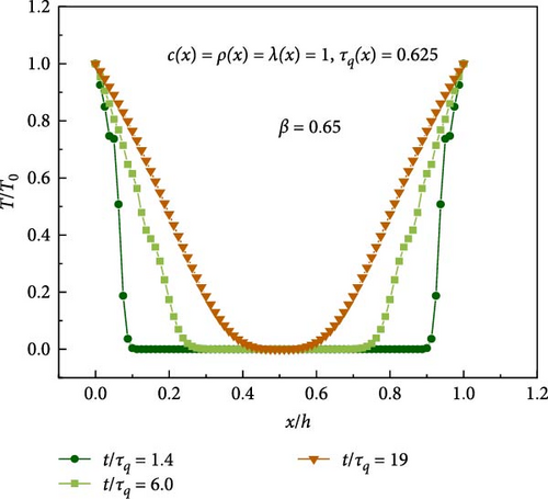
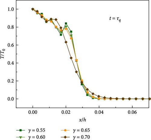
The convergence of numerical results with respect to γ are studied. As shown in Figure 4, the oscillations of transient temperature are compared among four different values of γ (γ = 0.55, 0.60, 0.65, 0.70). It can be found that the oscillations of numerical results decrease with the increase of γ. However, inaccurate numerical results are obtained when γ is equal to 0.70, which may be caused by the artificial damping of the Newmark method [52]. Therefore, to balance the convergence and stability, the following parameters are adopted in the following numerical examples:
4.1.3. Dependence of Element Meshing
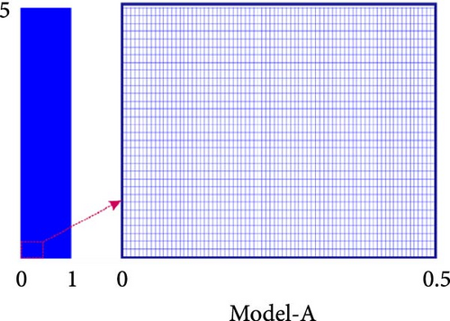
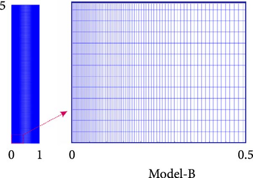
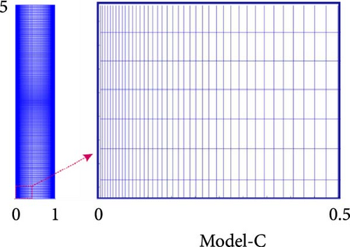
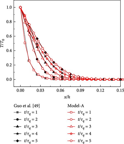
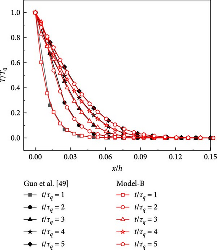
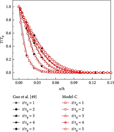
To verify the mesh dependence of numerical results by using the Newmark method, three different FEM models are chosen (Model-A, Model-B, and Model-C). As shown in Figure 5, there are 60,702 nodes and 60,150 elements in Model-A, 22,952 nodes and 22,650 elements in Model-B, and 12,312 nodes and 12,080 elements in Model-C. Figure 6 shows the transient temperature computed for different finite element meshing schemes (space increment). The results of transient temperature from the FEM models are perfectly coincident with each other, illustrating insignificant mesh dependence. Therefore, the integrations are computed using the meshing scheme Model-C in all the following examples. Time step and corresponding number of iterations as shown in Table 1.
| Number of iterations | 5 | 5 | 3 | 6 | 2 |
|---|---|---|---|---|---|
| Time step | 0.001 | 0.002 | 0.01 | 0.025 | 0.07 |
| Time | 0.005 | 0.01 | 0.03 | 0.15 | 0.14 |
4.1.4. Dependence of Iterative Time Step
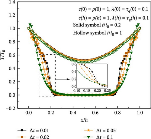
The iteration time step is an important factor affecting the calculation accuracy of the numerical method. Figure 7 shows the transient temperature response with varying time steps. It can be seen that the influence of the time step on transient temperature is larger, and the thermal wavefront of the small time step is obvious, which is the disadvantage of the present method. However, the computational efficiency can be improved by setting the adaptive time step to reduce the number of iterations. The time step is initially encrypted at extremely short time scales and then amplified with increasing time.
4.2. Transient Temperature Field in a Nonhomogeneous Plate With an Edge Crack
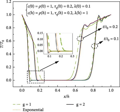
The transient temperature distributions for different materials distribution patterns of the FGM are compared in Figure 8. It is obvious that the difference in the temperature distribution changes with time.
The transient temperature distributions along the FGM plate thickness for different thermal relaxation times are shown in Figure 9. The thermal relaxation time affects the variation patterns of the transient temperature. The overshooting phenomenon [53] of transient temperature occurs at some positions and for different values of relaxation time. As the thermal relaxation time increases from 0.3 to 3, the overshooting phenomenon becomes milder. In particular, when the thermal relaxation time approaches 3, there is no temperature overshooting as shown in Figure 9. Therefore, there may be an optimal thermal relaxation time that minimizes the overshooting phenomenon. In addition, longer thermal relaxation time leads to a delay in the temperature response, because more time is required to reach a steady state.
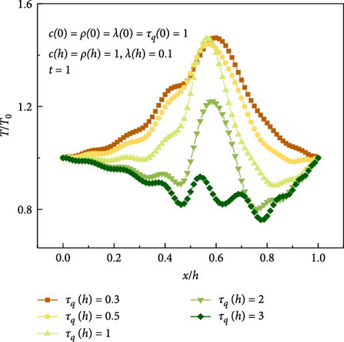
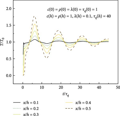
Figure 10 displays the variation of temperature along with the dimensionless time at different positions across the plate, denoted by various ratios of x to h. The value of the ratio varies from 0.1 to 0.5. The overshooting phenomenon of transient temperature becomes significant as the position x/h moves from the lower surface to the center of the plate.
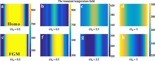
Next, the transient temperature fields are presented in Figure 11 at different times t/t0 = 0.2, 0.5, 2.5, and 5, respectively. It can be seen that the temperature distributes symmetrically in homogeneous material under symmetrical loading, and significant temperature fluctuations can be observed; temperature in FGMs propagates faster on the side with higher thermal conductivity. It should be noted that the present method can solve the transient temperature fields based on either hyperbolic heat conduction theory or Fourier heat conduction theory.
4.3. Thermal Stress Intensity Factor (TSIF) in an FGM Plate With Parallel Cracks
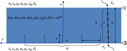
Here, KI and KII are Mode-I TSIF and Mode-II TSIFs, respectively, for the plane stress case, and for the plane strain case.
It should be pointed out that the crack at y = 0 is not affected by the boundary conditions when N takes an odd number. Therefore, the present work selects the crack at y = 0 to represent the parallel cracks in the FGM plate in the following calculations. The TSIFs can be normalized by . The normalized time is defined as t/t0 = λ1t/(c1ρ1h2). The thermomechanical parameters are shown in Table 2.
| Materials | Specific heat (J/kgK) | Thermal conductivity (W/(Mk)) | Coefficient of thermal expansion (×10−6/K) | Density (kg/m3) | Young’ modulus (GPa) | Poisson’s ratio |
|---|---|---|---|---|---|---|
| x = 0 | c0 = 456.7 | λ0 = 2.09 | α0 = 10.0 | ρ0 = 5331 | E0 = 151.0 | v0 = 0.33 |
| x = h | c1 = 537.0 | λ1 = 7.5 | α1 = 9.5 | ρ1 = 4420 | E1 = 116.7 | v1 = 0.33 |
To verify the IEIM, the current results are compared to the analytical results given by Noda and Guo [58], as shown in Figure 13. Perfect agreement between the results of the current method and analytical results verifies the correctness of the IEIM.
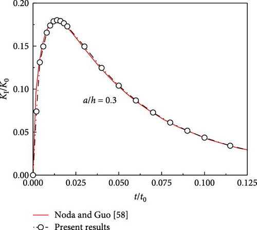
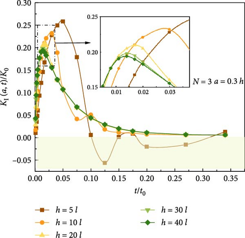
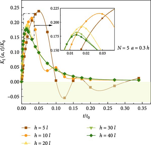
Figure 14 displays the relationship between the TSIF and plate thickness. It can be observed that the TSIF increases with the decreasing thickness, and there are some disturbances in the TSIF after the peak for small-thickness plates, which is caused by the thermal relaxation time. The parallel cracks still alternate between opening and closing after peak value when h = 5 l, so that the TSIFs fluctuate between positive and negative values.
Next, the influence of parallel crack spacing on the TSIF is shown in Figure 15. It can be observed that as the crack spacing decreases, the value of the TSIF decreases. Therefore, the occurrence of multiple parallel cracks may improve the fracture performance of the material.
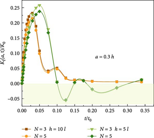
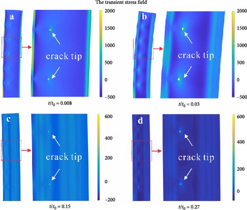
Figure 16 displays the transient stress field in the crack tip region of an FGM plate with parallel cracks (N = 5, a = 0.3 h) under transient thermal shock based on hyperbolic heat conduction. It is observed that the stress field exhibits obvious fluctuations because of the influence of thermal waves, and the fluctuations are more significant at the edges of the plate in the early stage of thermal shock, which is because the hyperbolic heat conduction is more suitable for small-sized spaces and short time.
The transient temperature field in nonhomogeneous materials is solved by the present scheme which can directly solve the second-order differential equation, without the need to convert it into a pair of first-order differential equations. As an example, the numerical results of FGM indicate that the transient temperature can be efficiently obtained, and obvious temperature overshooting occurs when considering the finite speed of heat propagation. Therefore, the present method can be applied to calculate the transient temperature in nonhomogeneous materials and can be combined with other methods to effectively deal with transient thermal fracture problems.
5. Conclusions
In this paper, a new finite element scheme using the Newmark integral method is provided for the computation of strong transient temperature based on hyperbolic heat conduction theories. The Newmark integral method enables the direct solution of a second-order differential equation of heat conduction. This study highlights significant scientific and industrial contributions, particularly in thermal analysis and fracture mechanics of nonhomogeneous materials under extreme thermal conditions. The novel finite element scheme using the Newmark integral method enhances transient temperature computation with improved efficiency, stability, and accuracy.
- 1.
The new finite element scheme is much more convenient for application than other available numerical methods. The numerical results of the transient thermal response agree very well with the theoretical results under thermal shock loading. The Newmark integral method for strong transient temperature shows excellent stability and accuracy, which is the major contribution of the present work.
- 2.
The overshooting phenomenon and the thermal wavefronts of transient temperature could be observed in nonhomogeneous materials based on the hyperbolic heat conduction theory, which is different from those in Fourier heat conduction. It is necessary to consider these effects in engineering applications under extreme thermal environments.
- 3.
By combining this present method with the interaction energy integration method, the fracture parameters can be effectively extracted. Therefore, this method can be readily combined with other methods to deal with transient thermal fracture problems.
Nomenclature
-
- q:
-
- Heat flux vector
-
- λ:
-
- Heat conductivity
-
- α:
-
- Thermal expansion coefficient
-
- c:
-
- Specific heat
-
- E:
-
- Young’s modulus
-
- ρ:
-
- Density
-
- T:
-
- Temperature
-
- τq:
-
- Relaxation time of heat flux
-
- Δt:
-
- Time step
-
- β, γ:
-
- Precision and stability parameter
-
- l:
-
- Characteristic length parameter
-
- κ:
-
- Thermal diffusivity
-
- N:
-
- Crack number
-
- K:
-
- TSIFs
-
- μ:
-
- Shear modulus
-
- s:
-
- Crack spacing
-
- t0:
-
- Normalized time
-
- a:
-
- Crack length
-
- h:
-
- Thickness of the FGM plate.
Conflicts of Interest
The authors declare no conflicts of interest.
Author Contributions
Yanyan Zhang: conceptualization, methodology, software, validation, formal analysis, investigation, data curation, writing–original draft, writing–review and editing, visualization. Tao Zheng: conceptualization, methodology, writing–original draft. Liangzhong Ao: writing–review and editing, funding acquisition. Shanqiao Huang: software. Zengtao Chen: formal analysis, investigation, resources, writing–review and editing, supervision, project administration, funding acquisition.
Funding
This work is supported by the Foreign Expert Program of the Ministry of Science and Technology (No. G2023203001L), the National Natural Science Foundation of China (No. 62406207), the Science and Technology Research Projects of Sichuan Province (No. 2023ZYD0135), and the Fundamental Research Funds for the Central Universities (No. ZJ2023-005, 25CAFUC01011, 25CAFUC04028, 25CAFUC09001).
Acknowledgments
This work is supported by the Foreign Expert Program of the Ministry of Science and Technology (No. G2023203001L), the National Natural Science Foundation of China (No. 62406207), the Science and Technology Research Projects of Sichuan Province (No. 2023ZYD0135), and the Fundamental Research Funds for the Central Universities (No. ZJ2023-005, 25CAFUC01011, 25CAFUC04028, 25CAFUC09001).
Open Research
Data Availability Statement
The data that support the findings of this study are available from the corresponding author upon reasonable request.


