An Improved Adaptive Frequency Sweep Strategies Based on Asymptotic Waveform Evaluation Technique for Broadband Antenna Simulation
Abstract
In this paper, we propose an improved adaptive frequency sweep strategy based on the asymptotic waveform evaluation (AWE) technique for simulating broadband antennas across a wide frequency range. Our approach maintains high accuracy compared to traditional frequency sweep methods, as demonstrated through simulation results of several commonly used broadband antennas. A novel error function is introduced specifically designed for broadband antenna simulation, which effectively improves the adaptive frequency sweep process. By analyzing the relationship between target error and computational time, we determine the optimal balance zone between efficiency and accuracy. Our findings provide valuable insights for efficient and accurate simulation of broadband antennas.
1. Introduction
Broadband antennas play a critical role in the field of communications, as they enable support for multiple frequency bands, high data transfer rates, and enhanced reliability for wireless communication systems [1]. Broadband antenna simulation is crucial for optimizing antenna performance, providing accurate predictions and guidance for effective signal transmission and reception, and making it an essential tool for achieving optimal performance and reliable communication systems [2].
The finite element method (FEM) is a widely adopted and accurate technique for antenna simulation [3]. However, accurately conducting frequency sweeps over a wide range poses a challenge in simulating broadband devices [4]. Traditionally, this challenge involves solving the frequency-dependent FEM system at each sampling point, resulting in computational expenses and practical limitations due to the high dimension of FEM matrices [5].
Model order reduction (MOR) [6] is a widely adopted technique for efficiently solving parameter-dependent linear systems of equations to reduce computational and memory costs [7]. These parameters typically involve frequency [8], material properties [9], and observation angles [10]. The MOR can be used to fast solve the optimization of array located on the PEC carrier inside the dielectric radome with parameters’ variation [11]. The article presents a new, efficient model-order reduction technique for microwave simulations, using a projection basis from FEM poles and zeros, with enhanced parallelism and accuracy compared to the reduced-basis method [12]. A streamlined self-adjoint sensitivity analysis for microwave components is presented using MOR, enhancing speed and accuracy in a wide frequency range [13]. One commonly employed MOR method for electromagnetic (EM) scattering [14], radiation [15], and waveguide [16] is the asymptotic waveform evaluation (AWE) method.
In the AWE method, the unknown vector is expanded into Taylor or Padé series, and the system is then approximated with a lower order approximation by moment matching [17]. A series of rational function interpolation/extrapolation algorithms have been developed for scattering parameter curves. Effective frequency sweep algorithms can be established by introducing Padé approximation [18] and Cauchy method [19–21]. In order to avoid derivative calculations at interpolation nodes, vector fitting methods [22], and Neville-type Stoer–Bulirsch methods [23] have been proposed for broadband microwave-circuit frequency sweep computations. Building upon Newmann’s impedance matrix fitting function [24], Yeo and Mittra [25] have developed a broadband frequency sweep algorithm for microstrip patch antennas to improve computational accuracy through segmented interpolation.
The range of validity of FEM-AWE decreases when the size of the problem increases, and this problem cannot be overcome simply by increasing the order of the Taylor or Padé approximation [26]. Multipoint (MP) must be used for FEM-AWE and ensure the accuracy of the antenna simulation over a width band [27]. The experimental results indicate that the accuracy and efficiency of MP algorithms are influenced by error indicators and adaptive strategies [28]. Furthermore, bisection is shown to be equally efficient as the greedy method, and both approaches demonstrate exponential convergence. An adaptive interpolation scheme divides sampling points into groups to mitigate Runge’s phenomenon and error fluctuations, applying varied strategies for accurate wideband response calculation in EM simulations [29]. In this paper, we propose a novel approach to improve the efficiency of the AWE and MP methods by investigating the target error and error-calculation function. A more effective solution is provided for addressing the challenges posed by complex systems. This strategy holds significant promise for enhancing the efficiency and accuracy of broadband antenna simulation methods crucial in modern telecommunications and radar systems. By addressing the limitations of existing methods, our approach not only aims to improve simulation outcomes but also opens doors to broader applications in antenna design optimization and EM compatibility testing.
In this paper, the formulation of the AWE based on Taylor and Padé expansion is elaborated in Section 2.1 and Section 2.2. The comprehensive flow of the adaptive frequency sweeping method is detailed in Section 2.3. We conduct extensive experimentation using several commonly employed broadband antennas to validate the accuracy of the AWE-FEM. The details are elaborated upon in Section 3.1, Section 3.2, and Section 3.4. In addition, in Section 3.4, we propose and validate several techniques aimed at enhancing the effectiveness of the adaptive frequency sweeping method. Finally, in Section 4, we provide a concise summary and conclusion of our research.
2. Methods
2.1. Formulation of AWE-Taylor Method
2.2. Formulation of AWE-Padé Method
By substituting coefficients ai and bj into equation (5), the unknown vector x(k) can be solved across a frequency band, and then calculate the S-parameter response of the broadband antenna.
Expand approximate functions using the Taylor series. Taylor series is an approximation at a certain point, which contains information about the derivative of a function at that point. The AWE-Taylor method usually performs well in areas where the function changes smoothly. Padé approximation is a rational function approximation that combines the polynomial part of Taylor series and its reciprocal polynomial to improve behavior approaching singularities. The AWE-Padé method is usually more stable when dealing with high-frequency oscillation problems [32].
2.3. Adaptive Frequency Sweep Methodology
Through the AWE, a solution can be obtained, but this solution only maintains good accuracy in the vicinity of the expansion frequency point. If the frequency is far from this expansion point, the accuracy of the solution cannot be guaranteed in general. In practical broadband antenna simulations, a MP expansion strategy [15] is generally necessary.
- (1)
Initialization:
-
Let kmin = k1 and kmax = k2 represent the minimum and maximum frequencies, respectively.
- (2)
Expansions:
-
Perform expansions around kmin and kmax to obtain approximations of X(k). Denote the approximation obtained from the expansion around kmin as X1(k), and the one from the expansion around kmax as X2(k).
- (3)
Point Selection and Computation:
-
Choose one or several points, ki, within the frequency interval. Compute the corresponding values of X1(ki) and X2(ki) using the respective expansions.
- (4)
Accuracy Check:
-
Calculate the sum of the absolute differences between X1(ki) and X2(ki).
-
If the sum is less than δ, the iterations are considered complete, and the desired accuracy is achieved.
-
Otherwise, proceed to the next step.
- (5)
Interval Bisection:
-
Bisect the original frequency interval [k1, k2] into two subintervals, namely, [k1, (k1 + k2)/2] and [(k1 + k2)/2, k2].
-
Repeat the entire process from step 2 independently for both subintervals.
- (6)
Iterative Refinement:
Continue iterating by selecting new points and recalculating X1(ki) and X2(ki) until the sum of the absolute differences between X1(ki) and X2(ki) falls below δ for all chosen points in each subinterval.
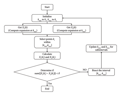
This iterative approach ensures that the entire frequency interval [k1, k2] achieves a reasonable accuracy level within the target accuracy δ. It allows for refining the approximations through successive iterations, bisecting the interval when necessary, and evaluating the accuracy at selected points. The process continues until the desired accuracy is obtained. The flowchart of adaptive frequency sweep methodology–based AWE algorithm is shown in Figure 1.
3. Numerical Results
To validate the accuracy and precision of the algorithms, this paper provides three commonly used broadband antenna structures. All simulations were performed on a PC platform, utilizing an Intel(R) Core(TM) i7-8700 CPU operating at a clock speed of 3.2 GHz. The mesh size used in the simulation cases in this study was set to 0.1 times the wavelength of the highest frequency. During the frequency sweep process, the size of the mesh remains unchanged.
3.1. Vivaldi Antenna
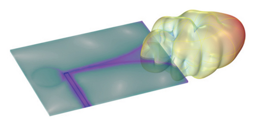
The first numerical example is the Vivaldi antenna [33, 34]. The structure, current distribution, and radiation of the Vivaldi antenna at 5 GHz are shown in Figure 2. It is implemented on a thin dielectric substrate by printing a gradient slot pattern on the top of the substrate. A simple exponential function e0.044x is used to form the gradient slot curve, with one end of the slot open and the other end featuring a circular slot. A 50 Ω microstrip feed line is set at the bottom of the substrate. The dielectric substrate of the antenna has the following parameters: width 110 mm, depth 80 mm, thickness 1.524 mm, and relative permittivity εr = 3.38. The width of the gradient slot is 0.5 mm, the width of the feed line is 3.2 mm, the length of the feed line is 40.25 mm, and the height of the feed line is 1.524 mm. This design aims to achieve broadband performance on a thin dielectric substrate by effectively radiating and receiving EM waves through the gradient slot pattern and circular slot structure.
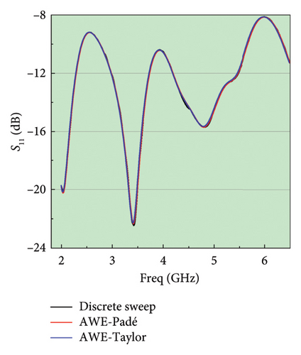
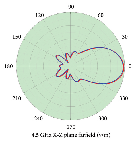
The simulation results of the S11 of the Vivaldi antenna and the radiation pattern in Figure 3 demonstrate the complete consistency between the discrete sweep frequency method, AWE-Padé algorithm, and AWE-Taylor algorithm. The consistency of the different algorithms has been robustly ensured across various directions and broad frequency ranges.
3.2. Spiral Slot Antenna
The spiral slot antenna exhibits circular polarization, frequency independence, and consistent impedance and radiation patterns across a wide frequency range [35, 36]. The spiral slot antenna consists of a dual-arm Archimedean spiral slot printed on a single-sided thin metal substrate using a parameterized curve. The excitation port is located at the center of the spiral slot for exciting the antenna. The selected dielectric substrate has the following parameters: radius 40 mm, height thickness 1.524 mm, and relative permittivity εr = 3.38. This design aims to implement a spiral slot antenna on a substrate by carefully constructing the Archimedean spiral slot. The parameters of the substrate and the configuration of the port are carefully chosen to maximize the performance of the antenna. We use a PEC to simulate the metal surface, which helps simplify the model and better understand the behavior of the antenna. Figure 4 illustrates the geometry, current distribution, and radiation characteristics of the spiral slot antenna operating at a frequency of 3.0 GHz.

Figure 5 shows that the S11 and radiation pattern of the spiral slot antenna exhibit almost perfect agreement between the discrete sweep frequency method and the AWE method based on either Padé or Taylor expansion. The results further demonstrate that the AWE algorithm is applicable to broadband circularly polarized antennas as well.
3.3. Log-Periodic Antenna
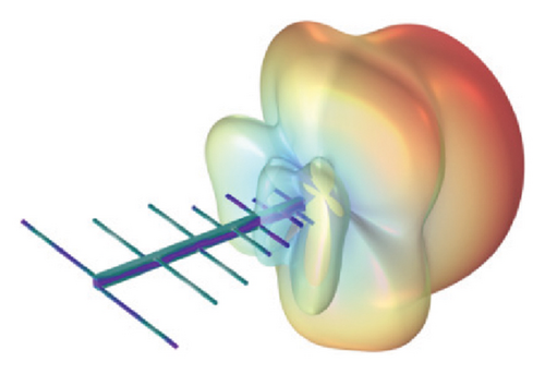
The log-periodic [37, 38] antenna is implemented by mounting a coplanar dipole array on a pair of metallic frames. The excitation port is located at one end of the gap between the two frames and also on a pair of shortest rods. It is noteworthy that the lengths of the dipole rods decrease along the direction towards the excitation port at a constant ratio. A repeating pattern of the radiation structure can be constructed using parameterized geometric parts.
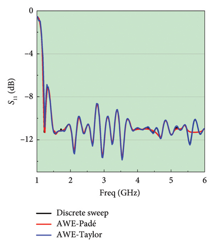
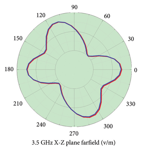
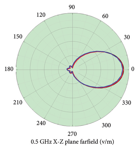
The specific parameters are as follows: the width of the metallic rods is 0.02 mm and the depth is 0.01 mm. The length of the longest rod in the dipole array is 0.2998 mm, the rod radius is 0.005 mm, the rod scaling factor ratio is 1.27, and the spacing between the first two elements is 0.15 mm. The gap size between the frames is 1 cm. Figure 6 depicts the geometric structure, current distribution, and radiation properties of the spiral slot antenna operating at a frequency of 0.75 GHz.
The simulation results depicted in Figure 7 provide evidence of the full equivalence between the discrete sweep frequency method and the fast sweeps method, as demonstrated by the matching S11 and radiation pattern of the log-periodic antenna. At approximately 0.7 GHz, some deviations were observed in the results obtained by the AWE-Padé and discrete sweep frequency algorithms. However, the AWE-Taylor algorithm consistently maintained a high level of accuracy. This observation suggests that, when subjected to the same relative tolerance, the Taylor expansion method achieves superior precision.

3.4. Comparison and Analysis
As depicted in Figure 8, we compared three different cases based on AWE-Padé to study the relationship between relative error and simulation time. When the relative tolerance is greater than 0.02, increasing the relative tolerance does not significantly reduce the simulation time. However, when the relative tolerance is set to less than 0.01, there is an exponential increase in simulation time, leading to a significant decrease in simulation efficiency. Based on the above analysis, setting the relative tolerance between 0.01 and 0.02 strikes a balance between simulation efficiency and accuracy.
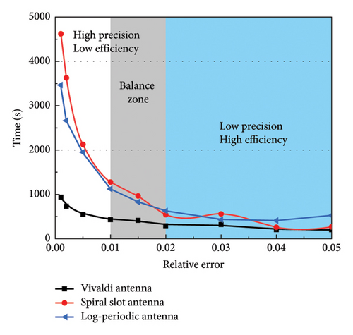
In the AWE-Padé method, the relationship between relative error and simulation time is determined by the precision requirements of the numerical solution process. When the relative tolerance is set relatively high (greater than 0.02), the simulation can be completed quickly with lower precision, as fewer iterations and less computational effort are required. However, when the relative tolerance is reduced to below 0.01, achieving higher precision necessitates more iterations and finer computations, which results in an exponential increase in computation time, thereby reducing simulation efficiency. Therefore, setting the relative tolerance between 0.01 and 0.02 allows for an optimal balance between simulation accuracy and computational cost, avoiding unnecessary computational overhead while ensuring result accuracy [39].
The AWE frequency sweeping algorithm, although effective in accurately depicting field behavior near resonant points and addressing high-Q value issues, has certain limitations [39]. For instance, it typically performs adaptive mesh refinement based on the center frequency of the frequency band, which may result in reduced accuracy at the band edges compared to the center. In addition, when the relative tolerance is set too low, computation time increases exponentially, impacting efficiency. Moreover, the AWE algorithm does not refine the mesh during the solution process which may restrict its application complex or highly variable EM field problems.
The S11 is related to the reflection of energy by an antenna, while the quantity is related to the radiation capability of the antenna. From a physical perspective, both functions can reflect the performance of the antenna. When comparing their numerical result, it can be concluded that the error function outperforms |S11| in Figure 9 and Table 1.
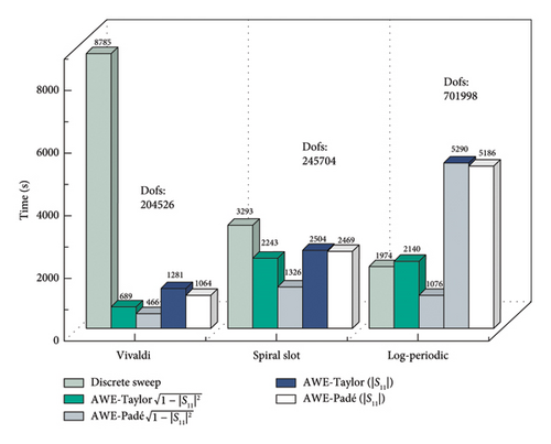
| Dofs | The time required for the simulations | |||||
|---|---|---|---|---|---|---|
| |S11| | ||||||
| FEM | AWE-Taylor | AWE-Padé | AWE-Taylor | AWE-Padé | ||
| Vivaldi antenna | 204526 | 8785 | 689 | 466 | 1281 | 1064 |
| Spiral slot antenna | 245704 | 3293 | 2243 | 1326 | 2504 | 2469 |
| Log-periodic antenna | 701998 | 1974 | 2140 | 1076 | 5290 | 5186 |
4. Conclusions
Based on the actual simulation results presented in this paper, several measures can be taken to improve the AWE algorithm–based broadband antenna simulation. Firstly, a relative tolerance setting between 0.01 and 0.02 is an efficient and balanced range for broad antenna simulations. Secondly, Padé expansion can be faster than Taylor expansion in broadband antenna simulations. However, for some null points, Taylor expansion may provide higher accuracy than Padé expansion. Finally, the error function is better than |S11|, especially in terms of efficiency. In conclusion, our study demonstrates the effectiveness of the proposed adaptive frequency sweep strategy in enhancing the accuracy and efficiency of the broadband antenna simulation. This advancement is poised to benefit various real-world applications such as satellite communications, 5G technology development, and radar systems. Furthermore, by improving simulation fidelity and reducing computational overhead, our approach lays a foundation for future advancements in broad band antenna design optimization and EM compatibility testing. As we look ahead, further research could explore integrating this strategy into commercial simulation software packages, thereby facilitating its widespread adoption and impact across industries.
Conflicts of Interest
The authors declare no conflicts of interest.
Funding
This work was supported by the National Natural Science Foundation of China (NSFC) under Grant 62303076, Chaohu University Key Scientific Research Projects under Grant XLZ-202206, the Anhui Provincial Colleges Science Foundation for Distinguished Young Scholars Grant 2022AH020093, Science Research Project of the Education Department of Anhui Province under Grant KJ2021A1024, Initial Scientific Research Fund of Young Teachers in Chaohu University Grant KYQD-2023066, and National Training Program of Innovation and Entrepreneurship for Undergraduates under Grant S202310380042 and 202410380021.
Acknowledgments
The authors thank Wiley’s English language service and MDPI’s English editing service for preparing this manuscript. The authors thank ChatGPT for assisting with the spelling and grammar checks throughout the drafting process of this paper.
Open Research
Data Availability Statement
The numerical and experimental data used to support the findings of this study are included within the article.


