Aerodynamic Performance Comparisons of Two Kinds of Variable Nozzle Vanes for a Variable Geometry Turbine
Abstract
Although cantilevered variable nozzle vane (VNV) is already used in engineering practice, few researches about cantilevered variable geometry turbine (VGT) aerodynamic performance can be found in public references. In order to find the difference between conventional and cantilevered VGT performances and provide references for VNV design practice, the aerodynamic performances of three single-stage VGTs with different VNVs were compared by the three-dimensional numerical simulation method. The VNVs of VGTs here included conventional, cantilevered, and no clearance VNVs. All three VGTs had spherical endwalls in the nozzle. The influences of nozzle spherical endwalls, vane end clearances, and vane rotation angles on VGT performances were investigated. The computation results show that the nozzle spherical endwalls enhance the radial mass flow immigration in the nozzle front part and increase the turbine mass flow rate by 0.79%. Some nozzle vane end clearance leakage flows near the vane trailing edge with higher axial speed can improve the mass flow rate further. Compared with the no clearance VGT, the conventional VGT efficiency is lower by 0.0082, and the cantilevered VGT efficiency is lower by 0.0293. When the VNV rotation angle increases by 1°, the VGT mass flow rate decreases by approximately 0.36 kg/s, and the expansion ratio improves by around 0.05. The cantilevered VGT had enormous VNV hub leakage loss, and its efficiency was lower than the conventional VGT by at least 0.01 within the range of VNV rotation angles. The cantilevered VNV hub creates more loss when VGT works at lower expansion ratio conditions.
1. Introduction
The future jet fighter will be equipped with properties of multipurpose, wide flight envelope, and high reliability [1, 2]. Both abilities of high thrust ability at high speed and low specific fuel consumption (SFC) at low speed are required for the advanced mixed mission jet fighter [3]. To meet this requirement, the development of a variable cycle engine (VCE) is suggested [4]. VCE is a sort of multipurpose aircraft propulsion system, and the research on VCE started in the 1960s [5]. VCE has various movable components which can change their geometric shapes in order to change the engine thermodynamic cycle type and rematch components [6]. For instance, in subsonic flight, VCE uses turbofan mode to reduce SFC. In supersonic flight, VCE closes the bypass and uses turbojet mode to increase thrust [7]. The variable geometry turbine (VGT) is one of the core components and technologies of VCE [8]. VGT can alter the engine’s common operating point through the adjustment of the variable nozzle vane (VNV) [9]. VNV realizes its movement by pivoting at the ends of the vane. The vane can rotate and change its stagger angle. When VNV is open, the nozzle throat area increases. When VNV is closed, the throat area reduces. In an aeroengine, mass flow rate is usually constrained by the turbine inlet vanes. Therefore, VNV can effectively control engine mass flow rate by changing the nozzle throat area. In this way, VGT can make engine components rematch, and then a better performance operating point can be reached. For example, VNV can be closed to decrease turbine output work with turbine inlet temperature nearly unchanged in part load condition. SFC of VCE can then be lowered than fixed geometry engine. In acceleration conditions, VNV can be opened to promote turbine work and lower the compressor operating line. Then, engine acceleration time can be shortened. In a two-spool VCE, VNV can provide modulation between high-pressure turbine (HPT) and low-pressure turbine (LPT) work splits to maintain optimum rotor speed match during different bypass operating modes [10].
The research on VGT started in the 1950s. The early representative studies of VGT include the work of Heaton, Holeski, and Forrette [11] and Campbell and Welna [12]. In Heaton, Holeski, and Forrette’s study, the performance of a scale model turbine was obtained in a cold air test facility with six different nozzle throat areas. The results showed that turbine efficiency decreased when the engine temperature ratio was above 5.0. Campbell and Welna studied a two-stage VGT in an altitude wind tunnel. The VGT was installed in the aeroengine model J40-WE-6 during the experiment. The turbine VNV was found to be mechanically reliable and have negligible leakage losses. When the corrected rotor speed was given, the turbine efficiency dropped after VNV was opened. The peak efficiency was obtained with the smallest nozzle throat area. After the above pioneer work, during the recent decades, many researchers devoted efforts to the development of VGT technology. In general, studies of VGT consist of different research fields, including thermodynamic cycle analysis [13], flow model establishment [14], aerodynamic performance study [15], and mechanical structure design [16].
Recently, in the aerodynamic performance study field of VGT, Huo et al. [17] studied the unsteady flow characteristics of a 1.5-stage VGT through numerical simulation and found that VNV total pressure loss increased linearly as vane end clearance height rose. Meanwhile, the turbine stage efficiency decreased linearly as the vane end clearance height rose too. Yue et al. [18] used a numerical simulation approach to investigate the effects of vane end configurations on a linear VNV cascade. The results showed the vane end cavity and pivot could suppress the radial secondary flow loss and end clearance leakage vortex. Besides, the intensity and scale of the passage vortex were magnified gradually as the vane stagger angle rose. Jiang et al. [19] conducted research on a VGT stage with cylindrical nozzle endwalls by numerical simulation. The research showed the aerodynamic characteristics of the VGT stage under the opening condition did not change so obviously as in the close condition. Gao and Huo [20] studied the aerodynamic performance of a VNV cascade under five different vane stagger angles and three different vane exit Mach numbers through the numerical method. Their study indicated that the close of VNV led to higher blade profile loss than the opening. Total pressure and energy losses decreased as the Mach number increased. Zhou and Zheng [21] proposed a novel spherical convex plat design method for VNV which could generate blockage for the vane end clearance leakage flow. They used numerical computation to study the effect of VNV spherical convex plat and suggested that the optimum position for spherical convex plat should be the place where the pressure gradient was the most aggressive. Wu, Fang, and Liu [22] studied the aerodynamic performance of a single-stage variable LPT by experiment. Their research showed that the adjustment of VNV had a more remarkable impact on the turbine mass flow rate than efficiency. Simultaneously, they proposed that the negative incidence angle and aft-loading blade design should be beneficial for VGT performance.
Usually, conventional VNV has pivots at both ends of the vane, while there is another structure for VNV design, that is, cantilevered VNV [23]. At the hub of cantilevered VNV, there is no pivot anymore, and the vane tip pivot is connected to adjustment machinery inside the outer endwall. Since the turbine works in high-temperature circumstance, the thermal deformations of turbine blades and endwalls are inevitable. When VGT is working, VNV may possibly be jammed and lose rotation function as a consequence of vane thermal deformation [24]. The cantilevered VNV, on the other hand, can reduce this jamming problem. Furthermore, it can also reduce the thermal erosion of hot gas on the turbine disk because there is not any hole or cavity on the nozzle hub endwall. The cantilevered VNV is already used in engineering practice [6, 25, 26]. Without a hub pivot, cantilevered VNV will certainly generate different influences on VGT aerodynamic performance compared to conventional VNV. However, few researches about cantilevered VNV aerodynamic performance from public references can be seen. The main purpose of the paper is to find the differences between conventional and cantilevered VGT performances and then provide a reference for VNV design practice. The three-dimensional computational fluid dynamics (CFD) method is used here which can help reveal flow details in turbines. Although the CFD method is applied widely in the VGT aerodynamics researches, differences in numerical methods exist among these studies. The reliability of the numerical method is a key element in the research. To guarantee the accuracy of numerical simulation results, the configurations of VNVs are carefully considered in the computational grids, and the numerical method is verified in detail. In the present work, the aerodynamic characteristics of single-stage VGTs with conventional and cantilevered VNVs are investigated. For comparison, the performance of a VGT with no clearance VNV is also computed. The influences of nozzle spherical endwalls, vane end clearances, and vane rotation angles on VGT performances are investigated.
2. Feasibility of Cantilevered VNV
At present, the majority of turbine VNVs have pivots at both ends of the vane. However, the cantilevered structure of VNV is also feasible in engineering practice. The adjustment mechanism of VNV is usually installed inside the turbine’s outer endwall. Therefore, the removal of the VNV hub pivot will not affect the adjustment function much. To apply cantilevered VNV in practice, the priority is to ensure the structural strength of the vane. The vane tip pivot needs to be strong enough. Besides, the shaft of VNV inside the outer endwall which drives the vane to rotate should be long enough and have at least two bearing points. In this way, VNV can be held stable. The cantilevered VNV is already used in some turbines. For example, the GT-225 variable geometry power turbine of General Motors Corporation is equipped with cantilevered VNV [25, 26]. GT-225 is an automotive gas turbine engine for passenger cars, and its power turbine VNV is mounted at the exit end of the turbine interstage diffuser outer endwalls. The VNV endwalls are spherical in order to minimize clearance leakage. The variable cycle turbofan engine TFE731 of AiResearch Manufacturing Company of Arizona also has cantilevered VNV in LPT [6, 27]. The variable LPT is used to drive a single-stage fan. The endwalls of LPT VNV are spherical, too. The above examples prove that cantilevered turbine VNV is feasible in engineering practice.
3. Research Turbine Objects
3.1. Original Turbine
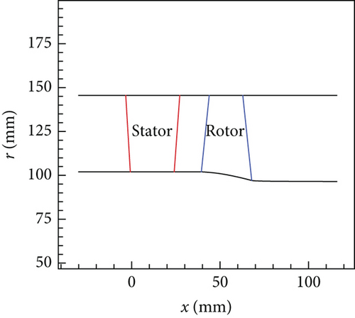
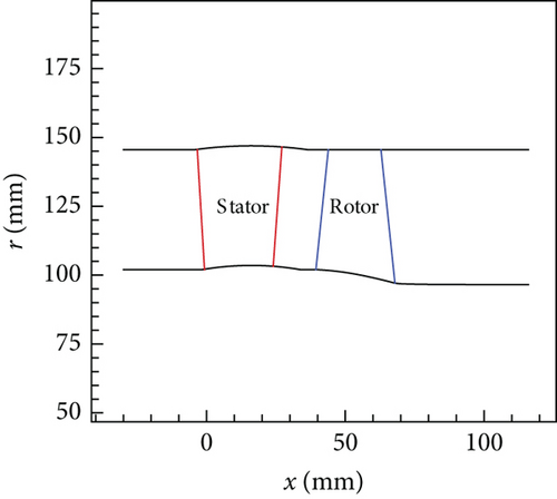
A single-stage turbine for a small aeroengine is used as the research object here and is designated as the original turbine. The original turbine has a constant outer endwall radius, and the outer endwall radius is 145.5 mm. The turbine inner endwall radius at the inlet is 102 mm, and the radius at the exit is 97.1 mm. The nozzle inner endwall radius is constant. The flow path of the original turbine is shown in Figure 1. There are 25 nozzle vanes and 46 rotor blades in the original turbine. The rotor tip clearance height is 0.46 mm. The design boundary conditions of the original turbine are exhibited in Table 1. In Table 1, pt0 is the turbine inlet total pressure, Tt0 is the inlet total temperature, pe is the exit back pressure, and n is the spool rotational speed.
| pt0 (kPa) | Tt0 (K) | pe (kPa) | n (r/min) |
|---|---|---|---|
| 652 | 1170 | 180 | 32,500 |
3.2. VGTs
Two kinds of nozzle VNVs (Figure 2) are studied here, and correspondingly, the original turbine is modified into two different VGTs. One VGT has conventional nozzle VNVs with pivots at both ends of the vane. The other one has cantilevered nozzle VNVs without a hub pivot. Since VNV end pivots can suppress the development of clearance leakage, increasing their sizes is beneficial to loss control. Pan et al. [28] proposed a sort of VNV end leakage-proof disk configuration to reduce the size of vane end clearance. This vane end disk is also used here. For the conventional VNV, both ends of the vane have disks. For the cantilevered VNV, only the vane tip has a disk. The vane end pivot splits the end clearance into two parts, and they can be called the leading clearance and the trailing clearance. At the cantilevered VNV hub, however, there is a full clearance. The vane end disk is inserted in the cavity of the endwall, and it is not contained in the vane flow passage, as illustrated in Figure 3. In order to study the effect of VNV clearance on VGT performance, another VNV which has no end clearance is also studied here, as shown in Figure 2(c). Of course, in engineering practice, the no clearance VNV is essentially unachievable. All three kinds of VGTs have the same design boundary conditions as the original turbine.
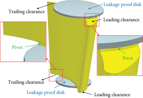
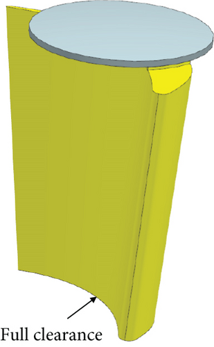
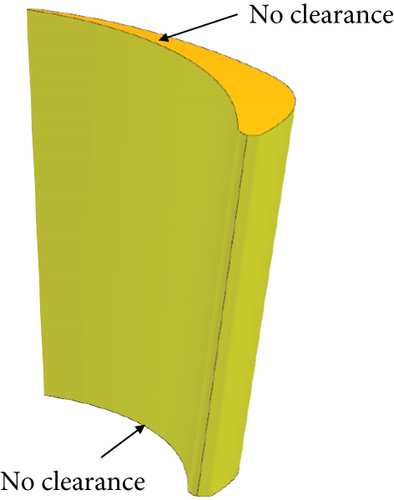
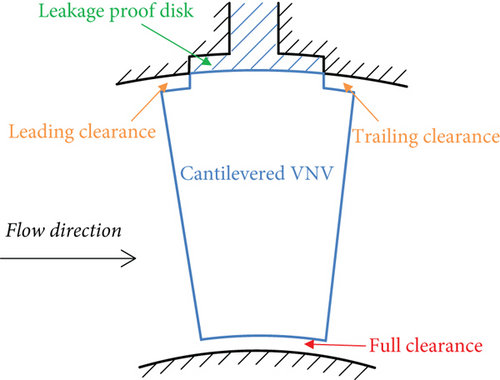
For the conventional VNV in Figure 2(a), the vane rotation axis is a radial line, which passes through the center of the vane tip camber line. The vane end disk diameter should be as large enough as possible for better leakage control. However, the diameter cannot be larger than the vane pitch length. Otherwise, the adjacent vane disks will interfere with each other. Furthermore, if the disk diameter is too large, the holes or cavities containing disks on the endwall will be very large as well. Then, the structural strength of the turbine’s outer endwall may be insufficient. At last, the vane tip disk diameter is decided to be the 4/5 of cascade tip pitch length with compromises. The hub disk diameter is also the 4/5 of hub pitch. The clearance heights at both vane ends are 0.46 mm, the same as rotor tip clearance. In order to avoid scratching of VNV on the endwalls during rotation of the vane, the VGT nozzle endwalls are designed to be spherical [29], as shown in Figure 4. Identically, the end plats of VNV are also spherical. The sphere centers of all the spherical surfaces above are at the same location (point O in Figure 4), which is located on the turbine spool axis. Meanwhile, the VNV rotation axis goes through the sphere center. In this way, the VNV end clearance is kept constant and uniform during adjustment, and leakage loss can be better controlled [29].
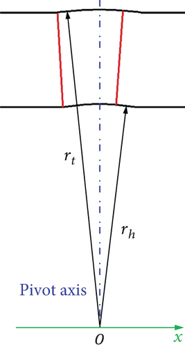
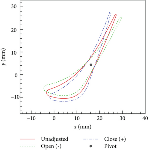
The radiuses of nozzle spherical endwalls (rh and rt in Figure 4) are related to the range of VNV rotation angle. They have to be large enough to ensure that VNV end clearance height is always unchanged, whatever the rotation angle is. The range of VNV rotation angle is set from −6° to 6°. The definition of rotation angle is illustrated in Figure 5. The negative rotation angle means opening VNV, and the positive rotation angle stands for closing. When VNV is not rotated, it is called unadjusted. The outer spherical endwall radius rt is 146.95 mm, and the inner spherical endwall radius rh is 103.52 mm. The structure of the VGT rotor blade is the same as the original turbine. Finally, the flow path of VGT in an unadjusted condition is depicted in Figure 6. The nozzle blade zone in the flow path changes when VNV is rotated. The VGTs with different VNVs are called the conventional, cantilevered, and no clearance VGTs here. In the following research, performances of VGTs with VNV rotation angles of −6°, −3°, 0, 3°, and 6° are investigated in detail.
4. Numerical Simulation Method
Detailed flow fields of the original turbine and three VGTs are simulated by the three-dimensional CFD method. Although the CFD method is widely used in VGT aerodynamics researches, there are differences in numerical methods among different studies. In order to simplify grid generation, some researchers ignore the rotation pivots of VNVs, and both ends of VNV have full clearances in the computational grids [19, 20, 30]. This simplification of VNV configuration is certainly unsuitable in the present study. Because the influence of VNV pivot on VGT performance is an important research target. In references [17, 28], the VNV end clearances are considered in VGT computational grids. However, the detailed grid quality and independence verifications are not given. So far, the guidelines of the VGT numerical method are still insufficient in public. To guarantee the accuracy of calculation results and provide guidelines for VGT flow simulation, the numerical method is carefully verified in this study at first.
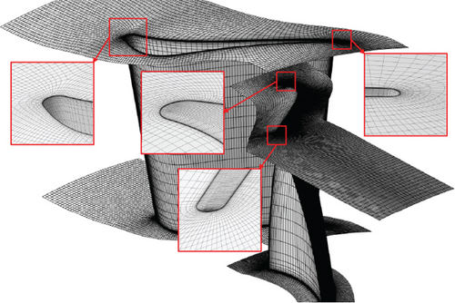
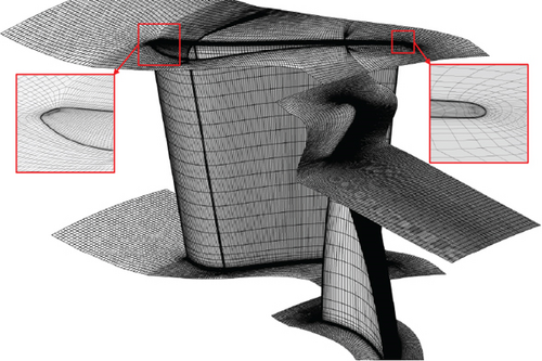
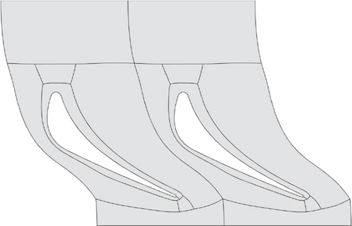
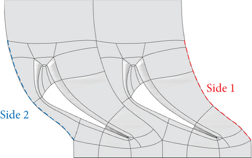
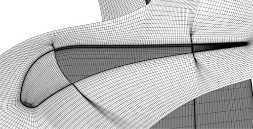
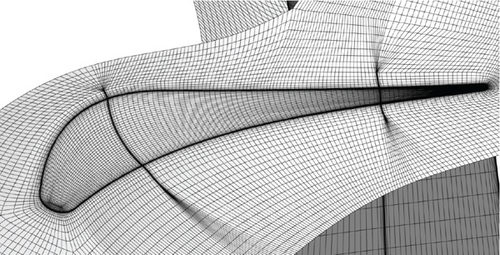
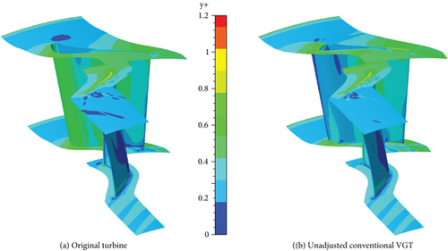
Here, the NUMECA software package is used to commence the numerical simulation. The single-channel structural grid is applied to computation. The IGG/AutoGrid module is used to generate grids. For the blade row without rotation pivot, O-H grid topology is used, as shown in Figure 7(a). The two sides of the grid domain in circumferential direction have identical grid node distributions, whose boundary conditions are applied with periodic matching connection (PMC). In the rotor tip clearance, the interfaces of the two adjacent grid blocks have different numbers of nodes. Therefore, a nonmatching connection (NMC) boundary condition is applied in the rotor tip clearance. For the VNV, a more complicated grid topology is used. In the VGT grid, VNV pivots are considered. Take the conventional VGT for instance, the grid of VGT in the unadjusted condition is demonstrated in Figure 7(b). The vane topologies at the tip endwalls of the original turbine and unadjusted conventional VGT are demonstrated in Figure 8. Figure 8(b) clearly shows that grid blocks are not fully matched in VGT vanes. The two sides of the nozzle grid domain in the circumferential direction are different from each other. As a result, periodic nonmatching connection (PNMC) is adopted instead of PMC. This nonmatching condition of structural grid sides also appears in references [17, 18]. The only difference between the conventional and cantilevered VGT grids is that the conventional VGT grid has a blank space at the VNV hub, which represents the pivot, as illustrated in Figure 9, while the cantilevered VGT has an additional grid block at the VNV hub to fill in the blank. To accurately simulate boundary layer flow, grids need to be refined near all the walls. y+ of the first layer of the grid cells near the wall is mostly less than 1.0, as shown in Figure 10. The maximum aspect ratio of grid cells is approximately 3000, the maximum expansion ratio is about 3.0, and the skewed angle is no less than 28°.
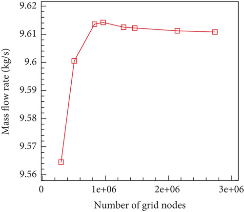
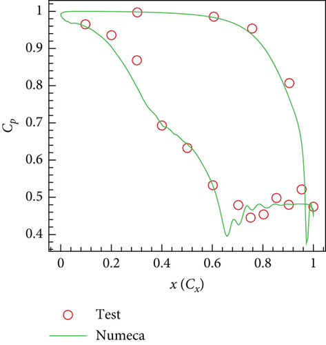
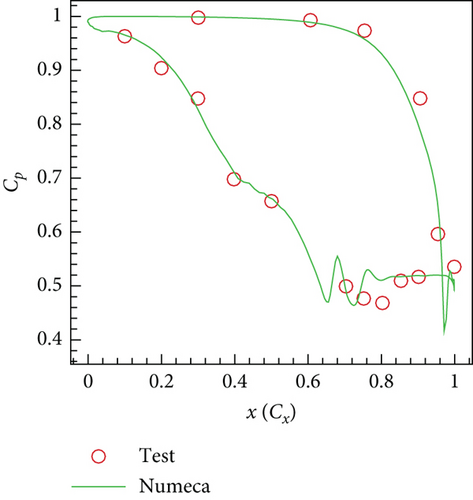
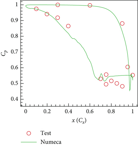
After grids are produced, the FINE/Turbo module is utilized to initiate flow field computations. The software solves Reynolds averaged Navier–Stokes equations (RANS) in steady condition. The numerical scheme is a finite volume scheme, and the Jameson central discretization method is used in space. The time scheme is the fourth-order Runge–Kutta scheme. Multigrid technology and local time step acceleration are implemented to accelerate convergence. To transfer flow data between the nozzle and rotor, the mixed plane method is used in the nozzle/rotor interface. The turbulence model used in the computation is the shear stress transport (SST) model. The SST model is widely used in the numerical computations of VGTs and can accurately predict VGT performances [28, 29, 31]. The turbine inlet boundary conditions include inlet total pressure and total temperature. The inlet flow is assumed to be uniform and axial. The turbine exit boundary condition is a static pressure condition based on radial equilibrium. Working fluid property is the combustion gas property, and specific heat at constant pressure is a function of temperature [32]. After calculations are finished, the CFView module is used to analyze flow field characteristics. To check the independence of the grid to computation, several grids with different numbers of nodes of the original turbine are applied to computation. The relationship between turbine mass flow rate results and the number of grid nodes is shown in Figure 11. In all, eight computation cases are calculated with different numbers of grid nodes.
5. Result Analysis
5.1. Turbine Performances at Design Boundary Conditions
The original turbine and VGTs are computed at design boundary conditions (Table 1). Detailed performance analysis and comparison are stated below.
5.1.1. Influences of Nozzle Spherical Endwalls and Clearances on Turbine Performances
At first, the aerodynamic performances of the original turbine and unadjusted VGTs are compared. The overall performances of these four turbines are exhibited in Table 2. In the table, mass flow rate m, expansion ratio π, and isentropic efficiency η are shown. In Table 2, “NC VGT,” “CV VGT,” and “CT VGT” stand for the no clearance, conventional, and cantilevered VGTs.
| Turbine | m (kg/s) | π | η |
|---|---|---|---|
| Origin | 9.612 | 2.760 | 0.9033 |
| NC VGT | 9.688 | 2.747 | 0.9068 |
| CV VGT | 9.715 | 2.743 | 0.8986 |
| CT VGT | 9.808 | 2.729 | 0.8775 |
Table 2 shows that the m and η results of the no clearance turbine are higher than the original turbine by 0.79% and 0.0035. π result of the no clearance turbine is lower than the original turbine by 0.013. The changes in the no clearance turbine’s overall performance result mainly from the change in the nozzle throat area. Comparing the original turbine flow path in Figure 1 with the VGT flow path in Figure 6, it can be found that the spherical endwalls have larger nozzle exit radiuses. At the axial location where the nozzle vane tip trailing edge is, the nozzle exit annular areas of the original turbine and no clearance VGT are 0.0338 and 0.0342 m2, separately. The VGT nozzle exit area is larger and consequently leads to higher m and lower π. VNV end clearances improve turbine m further while reducing π and η more. Compared with the no clearance VGT, the conventional VGT η is lower by 0.0082, and the cantilevered VGT η is lower by 0.0293. This means that the full hub clearance of cantilevered VNV generates a very high loss.
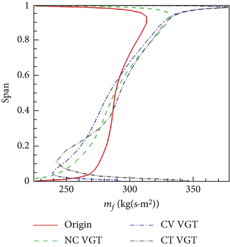
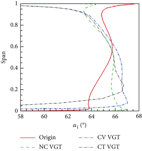
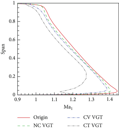
Figure 13(a) shows that the distribution of the original turbine nozzle exit mf is apparently different from VGTs. In the tip area, the VGT nozzle mf is higher, which means more mass flow immigrates radially from hub to tip in the VGT nozzles. Among the three VGTs, the cantilevered VGT nozzle mf has the most dramatic variance during the hub zone. This is a result of the strong radial secondary flow generated by the cantilevered VNV. Compared to the no clearance VGT, mass flow improvements of the other two VGTs mainly resulted from higher mf near endwalls. Figure 13(b) shows that the obvious difference of nozzle exit α1 exists between the original turbine and VGTs. In tip area, the original turbine nozzle α1 is higher. The distribution of α1 directly influences mf because higher α1 implies lower Vx. Therefore, the higher α1 is, the lower mf will be. Nozzle α1 close to endwalls of the conventional and cantilevered VGTs is very small because VNV end clearance leakage flows have higher Vx than main flows. In Figure 13(c), it can be seen that the nozzle spherical endwalls and end clearances reduce Ma1. The cantilevered VGT nozzle Ma1 at the hub is remarkably lower than the other three turbines. This indicates that the VNV hub full clearance significantly lowers the flow acceleration.
Figures 13(a) and 13(b) show that the nozzle spherical endwalls have larger influences on mf and α1 than the vane clearances. To investigate the cause of the differences of nozzle mf and α1 between the original turbine and no clearance VGT, meridian streamlines and Cp of the two turbines are exhibited in Figure 14.

Figure 14 shows that streamlines are almost horizontal from the inlet to the axial mean location of the nozzle in the original turbine. Due to the effect of the nozzle hub radial secondary flow, streamlines begin to turn upward during the axial latter part of the nozzle. In the no clearance VGT, however, the spherical endwalls make streamlines start to turn upward ahead of the nozzle. Meanwhile, the radial pressure gradient from tip to hub at the nozzle leading edge zone of the no clearance VGT is a little higher than the original turbine. This produces a radial driving force on the flow. Then, behind the nozzle, spherical endwalls make the streamlines close to the endwalls turn downward. Consequently, the streamlines in the tip area become denser. On the contrary, the streamlines near the hub become sparser. The density of local streamlines reflects the change of mf and α1. Denser streamlines will produce higher mf and lower α1. The difference of nozzle Cp in the two turbines is small. However, Cp at rotor hub in the original turbine is obviously lower than the no clearance VGT.
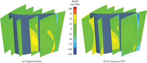
Figure 15 shows that the nozzle mf,r in the front part of the no clearance VGT is higher than the original turbine. This indicates that the radial mass flow immigration in the no clearance VGT nozzle front part is stronger. However, in the nozzle latter part, mf,r in the original turbine is higher. Besides, the nozzle mf,r behind the vane trailing edge near endwalls in the no clearance VGT has a lower negative value than the original turbine. Compared with the no clearance VGT, VNV end clearances promote turbine m further. Figure 13(a) shows that the major promotion of the nozzle mf by vane clearances is generated near endwalls. Nozzle exit distributions of mf and flow streamlines passing through high mf zones of the conventional and cantilevered VNVs are shown in Figures 16 and 17.
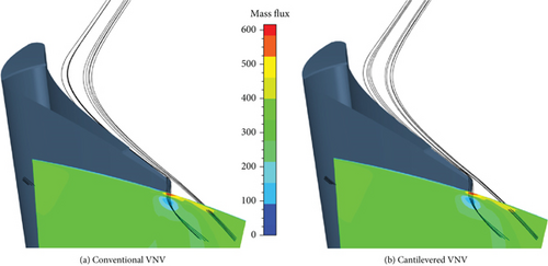
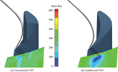
In Figure 16, the VNV exit mf distributions of the conventional and cantilevered VNVs are very similar. The streamlines passing through high mf zones indicate that the improvement of m is mostly contributed by the leakage flow near the vane tip trailing edge. Figure 17 shows that the m improvement at the conventional VNV hub also mainly resulted from the trailing edge clearance leakage flow. For the cantilevered VNV, though the vane hub structure has full clearance, the increase of m near the hub is still essentially contributed by the leakage flow near the vane trailing edge. However, the source flow of high mf leakage flow at the hub in the conventional VNV is closer to the endwall than the cantilevered VNV. The leakage flows promoting local mf all have high Vx.
Blade row total pressure loss coefficients of the original turbine and unadjusted VGTs are demonstrated in Figure 18.
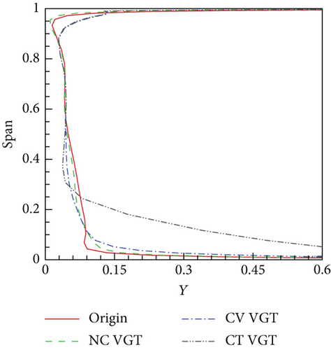
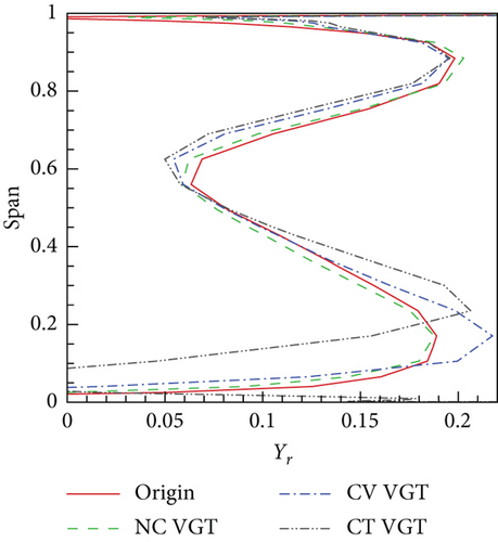
Figure 18(a) shows that the cantilevered VGT nozzle has an enormous loss at the hub. In particular, at 0.1 span, the total pressure loss Y of the cantilevered nozzle is about 0.4, while Y of the no clearance nozzle is 0.094 and Y of the conventional nozzle is 0.097. The loss difference between the no clearance and conventional VGT nozzles at the hub is not big. This proves that the VNV end pivot can effectively control vane leakage loss. From 0.1 to 0.5 span, there is a reduction of Y in the no clearance and conventional VGTs compared to the original turbine. However, below 0.1 span, nozzle Y of the no clearance and conventional VGTs is higher. According to Figure 15, cylindrical endwalls will create stronger radial flow movement in the latter part of the nozzle hub than spherical endwalls. Therefore, more of the thickened hub endwall boundary layer near the nozzle exit in the original turbine immigrates toward the main flow zone, which reduces the loss accumulation near the hub endwall but enhances the loss above 0.1 spans. From 0.25 to 0.5 span, the Y of the cantilevered VGT is the lowest. This indicates that the VNV hub full clearance weakens radial secondary flow further. In Figure 18(b), the difference of rotor relative pressure loss Yr distributions between the original turbine and the no clearance VGT is small. Rotor Yr during 0.55–0.9 span of VGTs is basically a little lower than the original turbine. This loss reduction is mainly a result of incidence angle improvement. Since the upstream nozzle α1 in VGTs is lower, the rotor positive incidence angle is smaller. At rotor hub, the distributions of Yr of different VGTs are quite different. The rotor loss peak at the hub of the conventional VGT is at the same radial location as the no clearance VGT. However, the loss of conventional VGT is higher. The rotor loss peak at the hub of the cantilevered VGT is at a higher location than the other two VGTs. Referring to Figure 13(b), the VGT rotor loss distribution difference is closely related to the upstream nozzle α1 which determines the rotor incidence angle distribution.
To explore the loading conditions of different VNVs, Cp and limit streamlines on the suction surfaces of VNVs are shown in Figure 19.
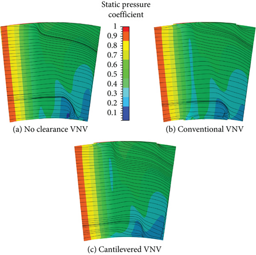
Figure 19 shows that VNV end clearances can optimize the aerodynamic loading on the vane suction surface to some degree. On the vane suction surface of the no clearance VNV, there are radial secondary flows in the tip area and a separation bubble ahead of the trailing edge at the hub. In the tip zone of the conventional VNV, according to the suction surface limit streamlines, the radial secondary flows are weaker than the no clearance VNV. Some flows near the tip clearances have a tendency to move into the clearances, so the radial flows are then weakened. At the conventional VNV hub, flows near clearances on the suction side also have the tendency to flow into the clearances. As a result, the separation zone on the conventional VNV suction surface ahead of the trailing edge is depressed which indicates the acceleration of flows near the trailing edge is reduced. Correspondingly, the radial size of the separation bubble at the hub is also reduced. On the cantilevered VNV suction surface, the radial secondary flows at the tip are stronger than the conventional VNV. The reason is that the hub full clearance structure absorbs too much more flows which enhances the radial movement toward the hub of main flows. On the other hand, the absorption of more flows by hub clearance depresses the flow separation further on the suction surface.
To analyze the structures of leakage vortices of different VNVs, end clearance leakage streamlines of the conventional and cantilevered VNVs are shown in Figures 20 and 21.
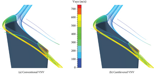
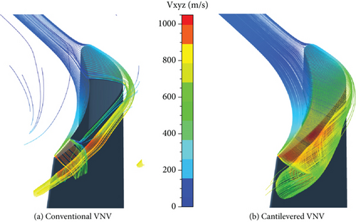
Figure 20 shows that the leakage flows of the conventional and cantilevered VNVs at the tip are very similar. The VNV tip pivot divides the leakage flow into two parts, that is, the leading and trailing edge clearance leakage flow. The trailing edge leakage vortex is more remarkable with a higher swirl speed than the leading edge leakage vortex. The speed of the leading edge leakage flow increases fast after the flow moves out of the clearance, and then the flow slows down. This implies that the leading edge leakage flow increases speed under the nozzle cascade favorable pressure gradient first and decreases speed next due to the mixing with the main flow. Most of the trailing edge leakage flows stem from the flows near the vane pressure side. A small amount of flows are absorbed into the trailing edge clearance from the nozzle vane suction side and then leave the clearance again. This absorption of flows from the vane suction side by the end clearance can depress the development of radial secondary flows. Figure 21 shows that much difference exists between the hub clearance leakage flows of conventional and cantilevered VNVs. First, without a hub pivot, more mass flows move into the clearance at the cantilevered VNV hub than conventional VNV. Besides, the cantilevered VNV hub leakage vortex is much stronger than conventional VNV. Therefore, it is clear that the VNV end pivot can effectively constrain the development of a clearance vortex.
5.1.2. Influence of Nozzle Vane Rotation Angles on Turbine Performances
The aerodynamic performances of VGTs with different VNV rotation angles are investigated here. The variances of overall performances of the three VGTs with VNV rotation angles Δθ are exhibited in Figure 22.
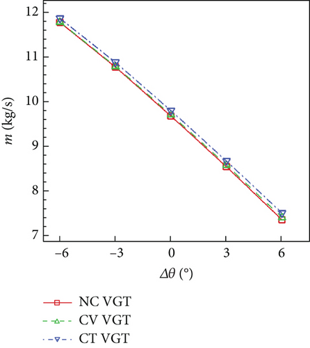
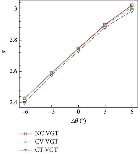
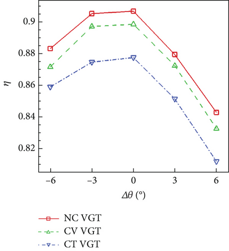
Figure 22 shows that whatever Δθ is, the no clearance VGT has the highest π and η, and the lowest m among the three VGTs. VNV end clearance will increase m but reduce π and η. The variance of m with Δθ is very close to a linear change in each VGT. When Δθ increases by 1°, m of each VGT decreases by approximately 0.36 kg/s, which is the 3.72% of the unadjusted no clearance VGT m. From −6° to 3° of Δθ, the variance of π of each VGT is also close to linear change. Each time Δθ increases by 1° within the range of −6° to 3°, π improves around 0.05. Each VGT has the highest η in an unadjusted condition. Both opening and closing of VNV will decrease η, and closing VNV will create more deterioration of η. The difference in performances between the conventional and cantilevered VGTs is generally bigger than the difference between the no clearance and conventional VGTs. η of the cantilevered VGT is lower than the conventional VGT by at least 0.01 and lower than the no clearance VGT by at least 0.024 during Δθ variance range.
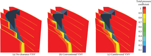
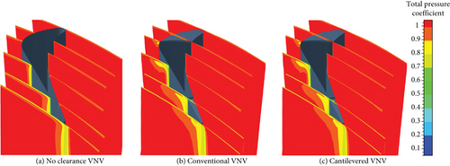
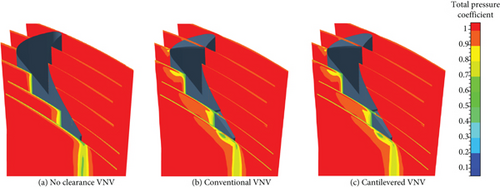
Figures 23, 24, and 25 show that the distributions of Cpt near the tip of the conventional and cantilevered VNVs are very similar at any Δθ. For the no clearance VNV, vane wake loss change is more obvious in close condition than opening condition. When Δθ is 3°, VNV wake loss is higher. The reason is that a closed VNV cascade has higher convergence which can increase flow speed. Simultaneously, the incidence angle of the vane gets higher, and the uncovered channel on the vane suction surface near the trailing edge becomes longer. Then, the boundary layer on the vane suction surface gets enhanced and is easier to separate. For VNVs with clearances, the tip leakage vortex cores can be found near the vane suction side. The tip leading edge leakage vortex becomes weaker along the vane suction surface downstream because the mixing of the vortex with the main flow makes the vortex dissipate. However, the thickness of the boundary layer on the suction side continues to increase from leading to the trailing edge. Compared to the unadjusted condition, when VNV is open, the leading edge leakage vortex becomes stronger, while the tailing edge leakage vortex becomes weaker. When VNV is closed, on the other hand, the opposite is the case. The reason lies in the loading distribution of vane change with Δθ. In opening condition, the front-loading property of the vane is enhanced. While in close condition, the aft-loading property is stronger. Higher local vane loading will increase the acceleration of local flow and then intensify the leakage vortex nearby. When Δθ is 3°, it can be found that wake losses of VNVs with clearances near the midspan zone are lower than the no clearance VNV. The reason is that the vane tip clearance reduces the speed of flow in cascade and depresses the radial secondary flow at the same time. Then, the development of the boundary layer on vane surfaces is controlled.
Cpt variances of different VNVs at the hub with different Δθ are shown in Figures 26, 27, and 28.
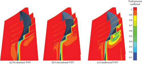
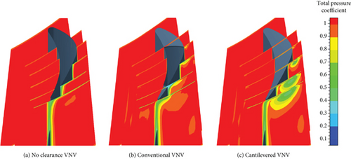
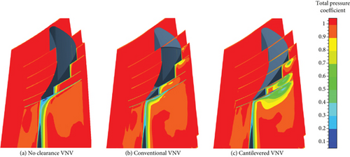
Figures 26, 27, and 28 show that the cantilevered VNV has a strong hub clearance leakage vortex. While the hub pivot of the conventional VNV manages to control the leakage loss. For the no clearance VNV, opening the vane can reduce wake loss near the hub, but closing the vane will increase wake loss. The reason lies in the loading distribution characteristics of the vane. Closing VNV will enhance the aft-loading property and increase boundary layer fraction loss. In the no clearance VNV, a remarkable corner vortex core loss zone can be found outside the cascade at the hub when Δθ is 0 and 3°. In the other two VNVs, the hub corner vortex zone is not seen anymore. For the cantilevered VNV, closing the vane makes the hub leakage vortex stronger, and the leakage vortex mainly expands its size in a circumferential direction. The cantilevered VNV has an obvious leakage vortex core zone at the hub. When Δθ is 0, −3°, and 3°, the lowest value of Cpt within the hub leakage vortex core zone at VNV exit is 0.379, 0.407, and 0.364.
The distributions of blade-to-blade (B2B) Mar of the no clearance VGT at 0.5 span with different VNV Δθ are shown in Figure 29. In the nozzle, Mar is exactly Ma.
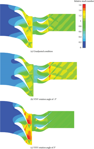
Figure 29 clearly shows the influence of VNV Δθ change on turbine Mar. When VNV is open, nozzle exit Ma decreases, and rotor exit Mar increases. When VNV is closed, however, nozzle Ma improves, and the rotor Mar reduces. This implies that closing the VNV will reduce rotor reaction and opening the VNV will increase rotor reaction. Besides, the change of VNV Δθ will change rotor inlet incidence angle. In an unadjusted condition, the rotor incidence angle at 0.5 span is nearly 0. When VNV is open, a negative incidence angle is produced at the rotor inlet, and the aft-loading property of the rotor blade is enhanced. When VNV is closed, rotor positive incidence angle is generated, and the front-loading property is enhanced. The front-loading property improves the acceleration of flow near the rotor blade leading edge on the suction surface and creates an adverse pressure gradient consequently. Simultaneously, the boundary layer separation near the trailing edge on the suction surface becomes fiercer.
The blade row total pressure loss variances of the three VGTs with VNV Δθ are demonstrated in Figure 30.
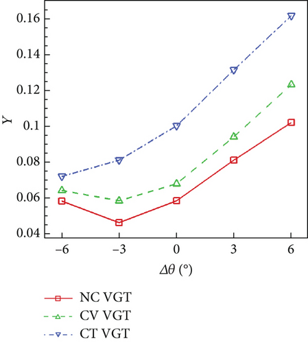
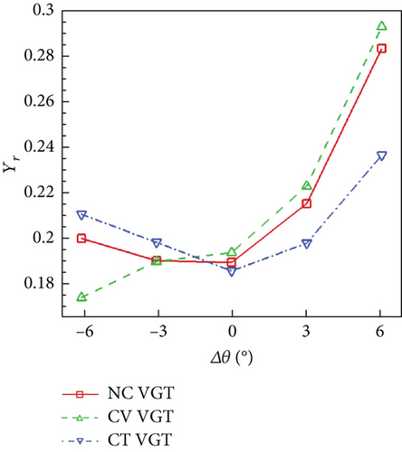
Figure 30(a) indicates that nozzle loss of the no clearance VGT is always the lowest among the three VGTs. As VNV Δθ increases from negative to positive, the cantilevered VGT nozzle Y becomes higher. However, for the no clearance and conventional VGTs, nozzle Y reduces first and then increases with Δθ increasing. According to Figure 29, when VNV Δθ is −3°, the flow in the no clearance VGT nozzle has a lower speed compared with an unadjusted condition. This can reduce the loss caused by the interaction of shock waves and the boundary layer on the vane suction side. But when the opening angle of VNV is higher, the nozzle cascade convergence will be degraded. A less convergent cascade enhances the front-loading property of the vane and makes the adverse pressure gradient of flow higher. As a result, nozzle Y increases. However, for the cantilevered VGT, as the opening angle of VNV changes from −3° to −6°, the nozzle Y keeps reducing. This resulted from the reduction of nozzle hub leakage loss since the hub leakage loss occupies a large proportion of overall cantilevered VGT nozzle loss. Figure 30(a) also shows that as Δθ changes from −6° to 6°, the nozzle loss produced by the cantilevered VNV clearances gets higher since the Y difference between the no clearance and cantilevered VGTs becomes larger. Besides, the cantilevered VNV clearances can get 60% more loss than the no clearance VNV when Δθ is within −3° to 6°. On the other hand, the loss increase by the conventional VNV clearances is generally no more than 20%. Figure 30(b) shows that for the no clearance and cantilevered VGTs, the minimum rotor loss is obtained in an unadjusted condition. However, for the conventional VGT, the rotor loss keeps decreasing as VNV reduces from 0 to −6°. To investigate the reason for rotor loss reduction of the conventional VGT, the distributions of Cp and limit streamlines on rotor blade suction surfaces of the three VGTs with VNV Δθ of −6° are compared in Figure 31.
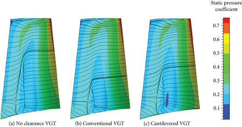
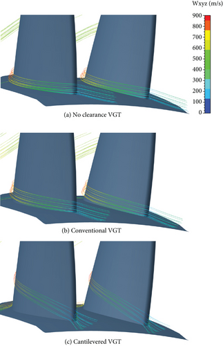
Figure 31 shows that the conventional VGT rotor blade has the smallest separation zone on the suction surface. While the no clearance VGT rotor blade has the largest separation area. This indicates that the rational upstream VNV hub clearance can improve the rotor flow condition to some degree when VNV is open. Compared to the no clearance VGT, Cp on the cantilevered VGT rotor suction near the hub is smaller. Even though the separation area of the cantilevered VGT rotor is smaller. The rotor flow condition is influenced directly by the upstream vane flow. In general, when VNV is open, the rotor inlet negative incidence angle is increased which makes the acceleration of flow at the rotor axial mean location higher. Consequently, a lower Cp zone is generated at axial mean location on the rotor suction surface. The adverse pressure gradient and flow separation are thus produced behind the low Cp zone. Another picture of rotor hub streamlines when Δθ is −6° is exhibited in Figure 32 for deeper investigation. Figure 32 shows that the conventional VGT rotor hub streamlines have a little stronger radial immigration than the no clearance VGT. This resulted from the VNV hub clearance which makes the radial speed Vr of the rotor inlet flow higher. This could intensify rotor loss because of the stronger radial secondary flow. However, the conventional VGT rotor inlet flow speed is a little lower, and the negative incidence angle is greater. At last, the flow separation on the rotor suction surface is depressed. But in the cantilevered VGT, the upstream VNV hub clearance is much larger, and a very strong radial secondary flow emerges at the rotor inlet, as shown in Figure 32(c). Despite this, since the cantilevered VGT rotor has a greater negative incidence angle than the no clearance VGT, the radial size of the cantilevered VGT rotor separation zone is reduced. The hub separation and secondary flows are the main causes of the higher rotor loss in the cantilevered VGT than the no clearance VGT. In all, Figures 31 and 32 prove that the VNV hub clearance can suppress the rotor flow separation on the suction surface at the opening condition but enhance the radial secondary flow at the same time.
5.2. Turbine Characteristic Lines at Different Rotational Speeds
By changing the turbine exit pressure pe and rotational speed n, different working points of VGTs on the characteristic map can be calculated. The turbine inlet condition, on the other hand, is kept constant which is always the design condition (Table 1). Characteristic lines of the no clearance, conventional, and cantilevered VGTs are displayed in Figures 33, 34, and 35.
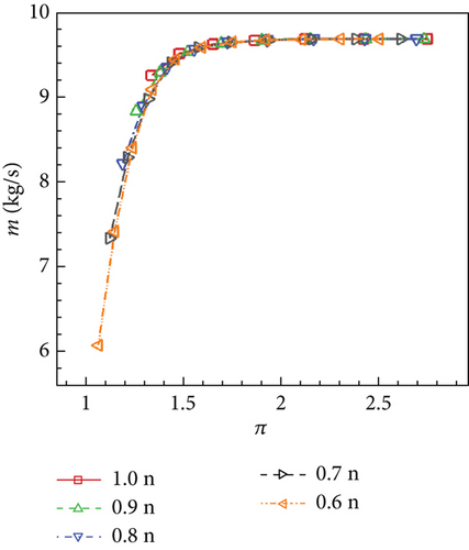
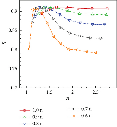
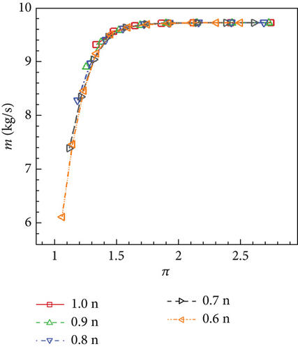
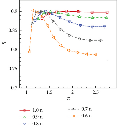
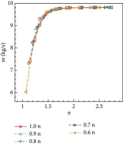
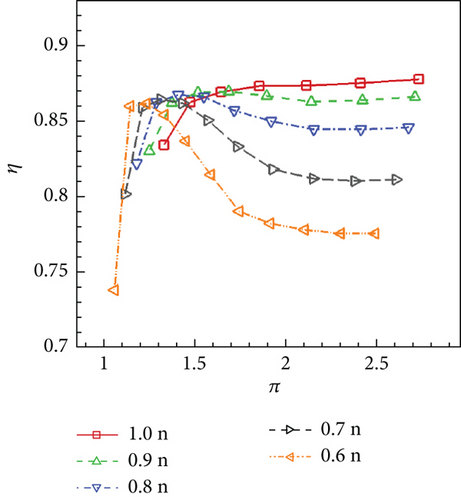
It can be revealed by Figures 33, 34, and 35 that the variance of n has little influence on VGT m performances. Given the same π, m of the conventional VGT is a little higher than the no clearance VGT, while the cantilevered VGT m is obviously higher. On the other hand, the variance of n has a remarkable influence on VGT η performance. As n reduces, generally, the peak η point on the characteristic line moves toward the left. The lower n is, the more rapidly η changes along the characteristic line. Compared to the no clearance VGT, the conventional VGT has a small reduction on each η line. However, the cantilevered VGT has a large η decline. Compared to the no clearance VGT, the cantilevered VGT η drops more when π gets lower. This indicates that the cantilevered VNV hub creates more loss when VGT works at lower π conditions.
5.3. Practical Ways to Reduce Cantilevered VNV Loss
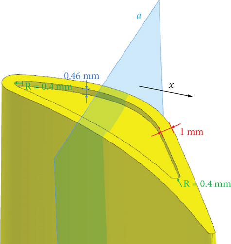
The above study results show that the cantilevered VNV will produce a large leakage loss. To reduce the efficiency penalty of the cantilevered VGT, more improvements are necessary for VNV configuration. Here, the vane tip leakage-proof disk is already introduced and studied above. It is an effective way to control VNV tip leakage loss. To reduce hub leakage loss of the cantilevered VNV, the vane end cavity can be used [18, 34]. To investigate the influence of the vane end cavity on VNV loss control, a new cantilevered VNV with a hub cavity is proposed, as shown in Figure 36. The cavity of VNV has a depth of 0.46 mm, the same as the height of the vane hub clearance. The leading and trailing edge radius of the cavity is 0.4 mm. Additional cantilevered VGT with this VNV cavity is calculated at design boundary conditions (Table 1), and the overall performance result is demonstrated in Table 3.
| m (kg/s) | π | η |
|---|---|---|
| 9.802 | 2.730 | 0.8791 |
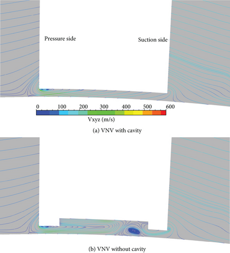
Compared with the cantilevered VGT performance in Table 2, the new cantilevered VGT with vane cavity has improved η by 0.0016. This proves that the vane end cavity can reduce leakage loss to some degree. To investigate the mechanism of loss reduction by cavity, the streamlines at the hub on plane a (shown in Figure 36) are exhibited in Figure 37. Plane a is perpendicular to the axial direction x and at the axial mean location of the cavity. Meanwhile, streamlines on the same location of the VNV without cavity are also shown in Figure 37. Figure 37(a) shows that there is a small vertex at VNV near the pressure side. While Figure 37(b) shows that the cavity makes the vertex near the pressure side grow larger. This vertex manages to force the flow in the clearance to move back to the pressure side and then control the leakage flow intensity. Besides, there is another vertex in the clearance near the suction side. This vertex also stops the leakage flow from moving from the pressure side to the suction side. In all, the vane end cavity can create vortices and backflow zones through the fierce expansion of clearance to reduce the leakage flows.
6. Conclusions
- 1.
The nozzle spherical endwalls can enhance the radial mass flow immigration in the nozzle front part and enlarge the throat area, improving nozzle exit mass flux and reducing the flow angle at the tip. While at the nozzle exit hub, mass flux is reduced and the flow angle is increased. The nozzle spherical endwalls here help increase the turbine mass flow rate by 0.79%. The mass flow improvement mainly resulted from the leakage flows with higher axial speed near the vane trailing edge.
- 2.
VNV end clearances will introduce extra leakage loss but can absorb some flows near endwalls and then depress the radial secondary flows to some degree. The cantilevered VNV has enormous loss and an intense leakage vortex at the hub, and the vane end pivot can effectively control leakage loss. The efficiency of the conventional VGT studied here is lower by 0.0082 than the no clearance VGT, while the cantilevered VGT efficiency is lower by 0.0293. In the conventional VNV, the trailing edge clearance leakage vortex is stronger with higher swirl speed. The leading edge vortex will be dissipated and weakened through the mixing with the main flow.
- 3.
The variances of VGT mass flow rate and expansion ratio with VNV rotation angles are close to leaner change. For the three VGTs studied here, when the VNV rotation angle increases by 1°, the mass flow rate decreases by approximately 0.36 kg/s, and the expansion ratio improves by around 0.05. The isentropic efficiency of VGT is at the highest value when VNV does not rotate. Closing VNV will cause more efficiency deterioration than opening. It mainly resulted from the intensified nozzle vane profile loss and the flow separation on the rotor blade suction surface.
- 4.
For the VGTs studied here, the cantilevered VGT efficiency is lower than the conventional VGT by at least 0.01 due to the higher leakage loss generated from the full clearance structure at the VNV hub. Meanwhile, the rotor loss of conventional VGT can be controlled better than the cantilevered VGT when VNV is open. The cantilevered VNV hub creates more loss when VGT works at lower expansion ratio conditions.
- 5.
The greatest benefit of cantilevered VNV is the reduction of jamming problems caused by vane thermal deformation and thermal erosion of hot gas on turbine disks. But the biggest limitation of cantilevered VNV is the remarkable hub leakage loss. To improve its applicability, leakage control methods like vane end leakage proof disk and cavity can be added. The future study of cantilevered VNV should be focused on the innovative and effective leakage control structures of the vane.
Nomenclature
-
- CFD
-
- computational fluid dynamics
-
- HPT
-
- high-pressure turbine
-
- LPT
-
- low-pressure turbine
-
- NMC
-
- nonmatching connection
-
- PMC
-
- periodic matching connection
-
- PNMC
-
- periodic nonmatching connection
-
- RANS
-
- Reynolds averaged Navier–Stokes equations
-
- SFC
-
- specific fuel consumption
-
- SST
-
- shear stress transport
-
- VCE
-
- variable cycle engine
-
- VGT
-
- variable geometry turbine
-
- VNV
-
- variable nozzle vane
Conflicts of Interest
The authors declare no conflicts of interest.
Funding
The authors received no specific funding for this work.
Open Research
Data Availability Statement
The data used to support the findings of this study are included within the article.


