Improved CO Selectivity via Anion Exchange Membrane Electrode Assembly-Type CO2 Electrolysis with an Ionomer-Coated Zn-Based Cathode
Abstract
Zn is a promising electrocatalyst candidate for CO production via CO2 electrolysis because of the moderate binding energy of ∗COOH intermediate. However, its thermodynamically unstable properties could cause performance degradation, particularly in conventional H-type electrolysis systems where the electrocatalyst is directly in contact with the electrolyte. Herein, we investigate the unstable characteristics of Zn-based cathode and suggest employing the anion exchange membrane electrode assembly- (AEMEA-) type CO2 electrolysis system to mitigate the electrolyte effects and enhance the catalytic performance. Unlike the conventional H-type electrolyzer, an AEMEA-type electrolyzer with a zero-gap configuration could mitigate the electrolyte effects on the cathode, thereby suppressing surface oxidation of the Zn-based cathode during the electrochemical reaction. Furthermore, the anion exchange ionomer layer on the cathode provides numerous ion pathways between catalyst and membrane interfaces and increases catalyst utilization that enhances the activity and selectivity for CO production via CO2 electrolysis. The above results suggest the breakthrough of using unstable materials as a catalyst for CO2 electrolysis and achieving reasonable performance.
1. Introduction
CO2 electrolysis, which electrochemically converts CO2 into various hydrocarbon fuels, has the potential to reduce the dependence on fossil fuels and restrain the acceleration of global warming [1–4]. Among the products obtained via CO2 electrolysis, CO presents advantages in commercial utilization owing to its market price and wide range of applications [5–9]. Many studies have reported that Zn, which exhibits reasonable performance for CO production with high selectivity [10–14], has considerable interest as an alternative to noble metals such as Au and Ag [15–20]. However, Zn has a low standard reduction potential (E°: –0.76 VNHE), and it is easy to chemically oxidize to hydroxide where the Zn is used as an electrode in conventional H-type electrolyzer [21]. Moreover, the thermodynamically unstable Zn dissolves into the electrolyte, which becomes more serious under acidic conditions. These corrosion phenomena could lead to stability issues during the CO2 electrolysis with a Zn-based catalyst [22]. Thus, minimizing the direct contact between the catalyst surface and the electrolyte is necessary.
Meanwhile, CO2 electrolysis using a gas diffusion electrode is attracting attention because it can overcome the mass transfer issues by directly supplying gaseous CO2 onto the catalyst surface, thereby achieving hundreds of milliamperes per square centimeter for the desired reactions [23–25]. Among the gas-phase CO2 electrolysis systems, a membrane electrode assembly- (MEA-) based system consists of a cathode, anode, and polymer membrane located between two electrodes with zero gap [23, 26–28]. Because of MEA configuration with zero-gap design, no catholyte layer is required, thereby improving the energy efficiency of the system and mitigating direct contact between catalyst and electrolyte [29].
In particular, the anion exchange membrane (AEM) provides an alkaline atmosphere near the cathode suitable for CO2 electrolysis, resulting in the fact that the AEM-based MEA- (AEMEA-) type electrolyzer system exhibits higher product selectivity than the proton exchange membrane- (PEM-) based MEA- (PEMEA-) type one [30, 31]. Furthermore, many studies for combining the anion exchange ionomer (AEI) onto the cathode have been conducted to further improve the performance via CO2 electrolysis [32–34]. Kim et al. confirmed that the AEI layer contributed to increasing the local CO2/H2O ratio because the AEI can impede the cation transport owing to Donnan exclusion [32, 35]. Patru et al. also investigated the influence of an alkaline environment near the cathode onto CO2 electrolysis [33]. In addition, the application of AEI, which has the advantages of providing ion pathway between catalyst and membrane interfaces and increasing catalyst utilization, could exhibit the improved CO2 electrolysis performance and stability [36].
Herein, we demonstrated the necessity of an AEMEA-type CO2 electrolysis system when using an unstable Zn-based electrocatalyst. First, we investigated the unstable properties of Zn-based catalyst under an aqueous electrolyte occurring morphological and chemical change. It was confirmed that employing the AEMEA-type electrolyzer system could well preserve the Zn-based catalyst during the CO2 electrolysis and enhance the activity with high CO selectivity. Moreover, the AEI layer onto the cathode provided the local alkaline environment and improved the performance of CO production via AEMEA-type CO2 electrolysis.
2. Experimental
2.1. Electrodeposition of Zn-Based Catalyst
The Zn-based catalyst for the CO2 electrolysis was fabricated by a facile electrodeposition method. A home-made Teflon cell with 1.44 cm2 of exposed area was used as the three-electrode cell system and was connected with a potentiostat (Autolab, PGSTAT302N, Metrohm). The working electrode had a microporous layer on a carbon paper (MPL/CP). A saturated calomel electrode (SCE) and a Pt wire were used as the reference and counter electrodes, respectively.
Prior to the electrodeposition, the MPL/CP surface was electrochemically pretreated at 5 mA/cm2 for 100 s in a 0.5 M (NH4)2SO4 solution to improve the surface hydrophilicity. The deposition electrolyte was composed of 0.2 M ZnSO4·7H2O, 0.5 M (NH4)2SO4, and 1.0 M H2SO4. The electrodeposition for the Zn/MPL/CP fabrication was conducted by applying a constant potential at –2.1 VSCE until the deposited charge amount was leached at –50 C. The deposition solution was N2-purged before the electrodeposition step to remove the dissolved O2 species.
2.2. Ionomer Coating on As-Prepared Zn/MPL/CP
The ionomer was spray coated on the as-prepared Zn/MPL/CP to further improve the CO2 electrolysis performance. The ionomer solution consisted of 736 μL of deionized water (DI), 64 μL of the ionomer (XA-9, Dioxide Materials), and 3.2 mL of isopropyl alcohol (IPA). The ionomer-coated Zn/MPL/CP cathode was dried at 50°C for 30 min to evaporate the residual IPA.
2.3. Characterization
Field-emission scanning electron microscopy (FESEM, Sigma, Carl Zeiss) and energy-dispersive X-ray spectroscopy (EDS, Thermo, NORAN System 7) analyses were conducted to investigate the surface morphology and bulk atomic composition of the as-prepared Zn/MPL/CP. The bulk crystal structure was also observed through X-ray diffraction (XRD, Bruker, D8 Advance). The electronic structure and surface composition were analyzed by X-ray photoelectron spectroscopy (XPS, K-alpha+, Thermo Fisher Scientific). In addition, the Raman (LabRAM HR Evolution, HORIBA) analysis was conducted to confirm the oxidation state of the Zn/MPL/CP surface.
2.4. Electrochemical Measurements in the Conventional H-Type Electrolysis System
The CO2 electrolysis performance in an H-type cell system was verified for 20 min at each constant potential. The as-prepared Zn/MPL/CP was used as the working electrode in an H-type electrolyzer. Further, Pt-mesh and SCE were used as the counter electrode and reference electrode, respectively. The working and counter electrodes were separated by a membrane, and Nafion 212 (Dupont Co.) and Sustainion X37-50 (Dioxide Materials) were used for the proton exchange membrane- (PEM-) based H-type electrolyzer and AEM-based H-type electrolyzer, respectively. The active area for electrodeposition was 1.0 cm2.
The CO2-purged and N2-purged 0.5 M KHCO3 electrolytes were contained in the cathode and anode, respectively. Then, the CO2 was continuously injected with a flow rate of 10 mL/min by modulating the mass flow controller (MKS Instruments, Inc.). The measured potential was converted to a reversible hydrogen electrode (RHE) with the following formula: ERHE = ESCE + 0.2412 + 0.0592 × pH. The outlet of each electrolyzer was connected to a gas chromatograph (GC, Agilent 7890B) to measure the concentrations of the gas products (H2 and CO).
The gas products from the electrolyzer were gained for 1 min before the end of each potential measurement, and simultaneously, the flow rate of the outlet was detected by the mass flow meter. The Faradaic efficiency (FE) for each product was calculated by integrating the concentration from GC, flow rate, and the charge amount during the time of product gained. The partial current density (PCD) which represents the current density for a specific product obtained was calculated by multiplying the total current density with FE.
2.5. Electrochemical Measurements in the MEA-Type Electrolysis System
Unlike the conventional H-type cell system, the MEA-type electrolyzer was connected with a two-electrode cell system. The Zn/MPL/CP was used as the cathode, and the commercial IrO2/CP (C0206 Dioxide Materials) was used as the anode. In the case of the MEA-type electrolyzer, the membrane (PEM: Nafion 212, Dufont Co., AEM: sustainion x37-50, Dioxide Materials) was located between the cathode and anode with a zero-gap configuration, where the active area was 1.0 cm2.
Humidified CO2 gas was supplied into the backside of the Zn/MPL/CP cathode with a flow rate of 200 mL/min. On the anode side, DI and 0.1 M KOH were injected with a flow rate of 20 mL/min for the PEMEA and AEMEA-type electrolyzers, respectively. The FE and PCD for CO and H2 from the MEA-based electrolyzer were calculated in the same manner as the H-type electrolyzer.
3. Results and Discussion
3.1. Characterization of the Instability of the Zn-Based Catalyst
Prior to testing the CO2 electrolysis performance, we investigated the unstable properties of the Zn-based catalyst under an aqueous electrolyte. The Zn/MPL/CP was fabricated by electrodeposition on the MPL/CP substrate (Figure S1), and the FESEM image shows that the Zn deposits with the hexagonal structure were well distributed (Figure 1(b)). However, when the as-prepared Zn/MPL/CP was immersed into a 0.5 M KHCO3 electrolyte, the hexagonal structure gradually changed to a dendrite (Figure 1). This morphological change in the Zn-based catalyst was due to the difference in the dissolution rates based on the crystal structures, which was confirmed in our previous study [37]. The conversion to the dendrite structure was saturated at an immersion time of 180 min, which indicates the unstable properties of the Zn materials in the electrolytes.
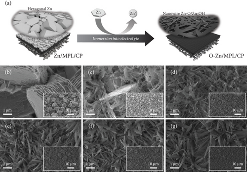
Figure 2 shows the comparison of the properties of the Zn/MPL/CP before and after immersion into the KHCO3 electrolyte. The structural change in the Zn/MPL/CP was investigated by XRD analysis (Figure 2(a)). For the as-prepared Zn/MPL/CP, three peaks were detected in the XRD pattern (JCPDS #87-0713): Zn(002) at 36.3°, Zn(100) at 39.0°, and Zn(101) at 43.2°, indicating that the as-prepared Zn catalyst was close to the metallic state. In addition, the Zn(101) facet was dominant in the as-prepared Zn/MPL/CP, indicating that it was suitable for CO production via CO2 electrolysis [13, 38]. After immersion into the 0.5 M KHCO3 solution for 180 min, the new peak appeared at 31.8°, corresponding to the ZnO(100) facet.
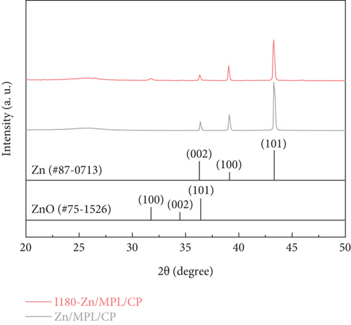
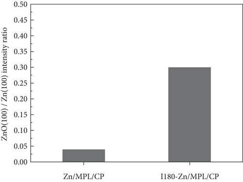

As shown in Figure 2(b), compared to the Zn/MPL/CP, the ZnO(100)/Zn(100) intensity ratio increased in the I180-Zn/MPL/CP where the immersed time was 180 min. The additional results of the XRD patterns of the Zn/MPL/CP with varying immersion times are presented in Figure S2a and b. The XRD analysis revealed that a direct contact between Zn and the electrolyte caused not only a morphological change but also a chemical change from a metallic to an oxidized state.
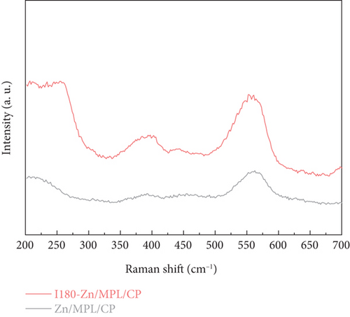
Ex situ Raman spectroscopy was conducted to investigate the change in the surface structure of the Zn/MPL/CP after immersion for 180 min. As shown in Figure 2(c), two peaks at 387 cm–1 and 560 cm–1 were observed, which correspond to the characteristic vibrational mode of ZnO [12, 39]. In the case of the I180-Zn/MPL/CP, an increase in the peak intensity was observed at 387 cm–1, 560 cm–1, and ~240 cm–1, which revealed that these are ascribed to the characteristic vibrational mode of Zn(OH)2 [40].
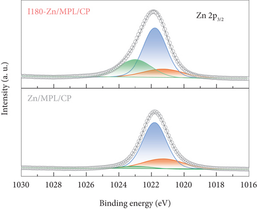
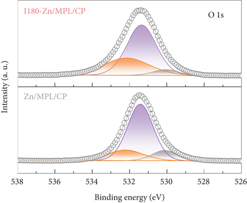
Further, we demonstrated the electronic structures of the surfaces of the Zn/MPL/CP and I180-Zn/MPL/CP using the XPS analysis. As shown in Figure 2(d), the XPS spectrum of the Zn 2p3/2 region was deconvoluted into three peaks: 1021.3 eV, 1021.8 eV, and 1023.0 eV, which were assigned to metallic Zn, Zn-O, and Zn-OH, respectively [41]. After the immersion into the 0.5 M KHCO3, the intensity of the metallic Zn was reduced, whereas those of the Zn-O and Zn-OH states increased. Meanwhile, three separated peaks were observed at O 1 s: 530.1 eV, 531.4 eV, and 532.2 eV, which were assigned to Zn-O, Zn-OH, and absorbed water molecules, respectively (Figure 2(e)) [41]. It was revealed that the ratio of Zn-OH and water molecules in the O 1 s peak increased after the immersion.
In addition, a significantly higher intensity at 376.6 eV representing the K 2 s state was observed in the I180-Zn/MPL/CP, which could be due to potassium incorporation into the surface (Figure 2(f)). The increase in the atomic compositions for O and K with the increasing immersion time was also confirmed by the EDS analysis (Figure S2c). The above results demonstrate that a direct contact between unstable Zn material and electrolyte causes surface oxidation and morphological changes.
3.2. Electrochemical Properties of the Zn/MPL/CP according to the Electrolyzer Type
Although various studies have reported on the high performance of the Zn-based catalysts in CO2 electrolysis, the stability issues of the electrocatalysts still remain unaddressed [11, 42]. In the conventional H-type cell for the CO2 electrolysis, a direct contact between the electrode and electrolyte is inevitable, leading to performance degradation. To investigate the corrosion resistance of the Zn/MPL/CP as a cathode according to the electrolyzer configuration, the cell voltage variation in the two-electrode cell system was measured during the open-circuit period (Figure 3 and Figure S3).
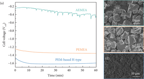
In the conventional PEM-based H-type electrolyzer system, the measured cell voltage was started at –1.47 Vcell; however, the value decreased dramatically to –1.6 Vcell over 10 min and was then saturated (Figure 3(a)). Furthermore, the hexagonal structure of the Zn/MPL/CP was agglomerated and transformed into a dendrite after the measurement (Figure 3(d)), which corresponds to the FESEM images in Figure 1.
On the other hand, in the case of the PEMEA-type electrolyzer, a smooth decrease in the cell voltage from –1.25 Vcell to –1.36 Vcell within 60 min was observed. The hexagonal Zn structure was well preserved after the test, although there were weak surface damages (Figure 3(c)). Similar trends were also observed in the AEMEA-type electrolyzer, as shown in Figure 3(b). The EDS analysis after the measurement revealed that the metallic Zn state of the Zn/MPL/CP was well maintained when using the MEA-type electrolyzer (Figure S4). It means that the presence of a polymer membrane can mitigate the chemical oxidation of the Zn-based catalyst surface [43]. However, it should be noted that the precise comparison of the cell voltage variation was difficult because the ion migration differed according to the membrane and electrolyte used. Nevertheless, it implies that using MEA-type electrolyzer is essential not only for enhancing the CO2 electrolysis performance but also for achieving durability.
3.3. Measurement of CO2 Electrolysis Performance according to the Electrolyzer Type
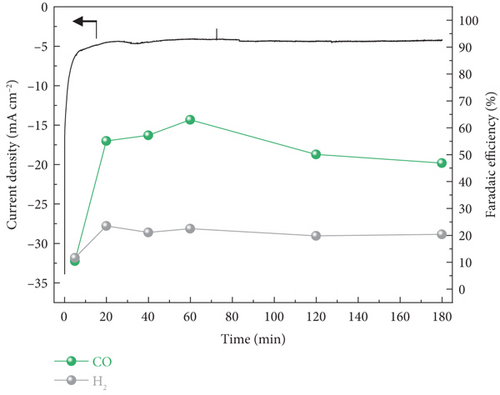
We investigated the CO2 electrolysis performance for 180 min at a constant potential according to the electrolyzer used (Figure 4). In the case of the PEM-based H-type electrolyzer, the Zn/MPL/CP cathode exhibited relatively low activity for the CO production at –1.0 VRHE due to the poor solubility of CO2 into the aqueous electrolyte (Figure 4(a)). Furthermore, the highest FE for the CO production was measured as 63% at 60 min, which steadily deteriorated with the increasing operation time. In addition to low CO2 solubility, the ohmic loss owing to the presence of an electrolyte layer contributed to low CO2 electrolysis performance.
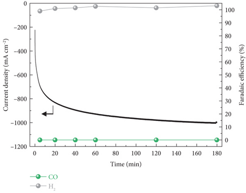
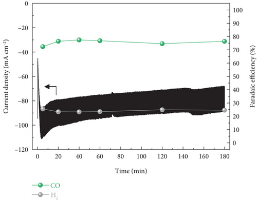
In the case of PEMEA-type electrolyzer, hundreds of total current densities at –2.8 Vcell were obtained and gradually increased during the reaction (Figure 4(b)). It was because of the MEA configuration leading to improve energy efficiency and facilitate the mass transport. However, the calculated FE confirmed the most of the current density contributed to the hydrogen evolution reaction (HER) which is competing reaction against electrochemical CO2 reduction. It was that the H+ generated via the oxygen evolution reaction at the anode was transferred to the cathode through the PEM. As a result, the H+ local concentration near the cathode surface was relatively higher than that of the CO2 reactant.
On the other hand, the current density for CO production via CO2 electrolysis was further enhanced in the AEMEA-type electrolyzer (Figure 4(c)). This indicated that the AEM could suppress the accumulation of H+ near the cathode mitigating the HER [44, 45]. Accordingly, the CO2 electrolysis was dominant at the cathode and the AEMEA-type electrolyzer exhibited ~76% of stable CO FE for 180 min. Although there was slight performance degradation during the 180-min operation, the CO FE was well maintained, implying that the catalytic properties were unchanged.
The surface morphology of the Zn/MPL/CP cathode after the CO2 electrolysis according to electrolyzer configuration was investigated by FESEM, which indicated that the Zn electrocatalysts were agglomerated with deformation in an PEM-based H-type system (Figure S5a). On the other hand, a damaged hexagonal surface was observed in the PEMEA-type electrolyzer due to the high H+ concentration near the surface (Figure S5b).
In the case of the AEMEA-type electrolyzer, the hexagonal fixture of the Zn/MPL/CP was well maintained after 180 min of CO2 electrolysis (Figure S5c). Furthermore, the AEMEA-type system exhibits the higher CO selectivity with high PCD at various applied potentials than other systems (Figure S6). This indicates that not only the MEA configuration, particularly when using AEM, but also the direct supply of gaseous CO2 could provide reasonable CO2 electrolysis performance while preserving the catalyst properties. The low K atomic ratio observed by the EDS analysis after the CO2 electrolysis also indicated that the contribution of the catholyte in the AEM-based electrolyzer was reduced (Figure S5d).
3.4. Ionomer Effects on the AEMEA-Type CO2 Electrolysis
To further enhance the CO2 electrolysis performance, we introduced AEI layer on the top surface of the Zn/MPL/CP by spray-coating. The AEI layer provides an ion pathway and improves the interface properties between the electrode and membrane that can maximize the reaction active sites. The amount of AEI content was controlled by repeating the spray-coating process.
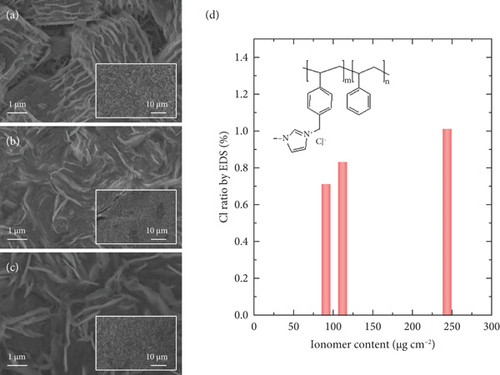
Figures 5(a), 5(b), and 5(c) show the FESEM images of the ionomer-coated Zn/MPL/CP cathode according to deposited AEI amounts. Compared to the as-prepared Zn/MPL/CP cathode (Figure 1(b)), the thin film was formed on the surface of the Zn/MPL/CP cathode containing 90.2 μg/cm2 of the AEI, and the hexagonal structure was well preserved (Figure 5(a)). As the AEI content increased to 111.1 μg/cm2, the hexagonal Zn interconnected with each other (Figure 5(b)), and an excessive amount of AEI (234.1 μg/cm2) blocked the CO2 gas passage (Figure 5(c)). Meanwhile, the EDS analysis indicated that with the increasing amount of AEI content, which consisted of chloride form, the Cl ratio increased (Figure 5(d)) [45].
The AEMEA-type CO2 electrolysis performance for the AEI-coated Zn/MPL/CP cathodes was measured at –2.8 Vcell for 20 min (Figure 6). The CO FE exhibited an increasing tendency with the increasing amount of AEI, as shown in Figure 6(a). Correspondingly, the CO PCD improved from –68.1 mA/cm2 to –107.8 mA/cm2 (Figure 6(a)). However, the excessive amount of AEI coating (234.1 μg/cm2) led to degradation of the CO PCD to –92.8 mA/cm2 because of blockage in the pore structure and reduced active sites, as shown in Figure 5(c).
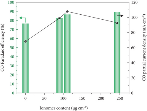
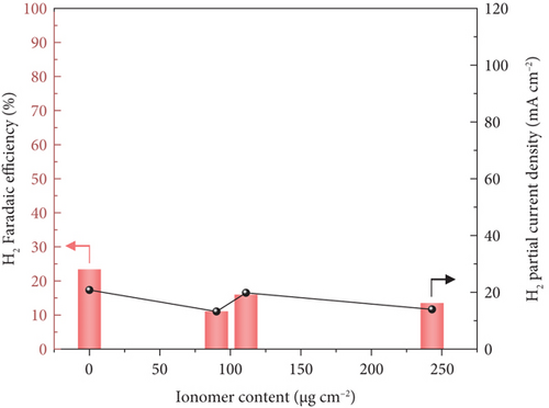
Meanwhile, the H2 FE and H2 PCD decreased after the AEI coating on the Zn/MPL/CP surface. It could be that the ionomer thin layer mitigates the accumulation of H+ and allows the enhancement of CO selectivity. In addition, during the AEMEA-type CO2 electrolysis at –2.8 Vcell for 180 min, the AEI-coated Zn/MPL/CP cathode exhibited higher CO FE and CO PCD than those of the bare Zn/MPL/CP cathode. The additional electrochemical performance of AEI-coated Zn/MPL/CP according to the operating time is shown in Figure S7.
Moreover, the FESEM images in Figure S8 confirmed the hexagonal structure of the Zn/MPL/CP with the AEI content was well preserved after the CO2 electrolysis for 180 min. This implied that the AEI thin layer could mitigate the access of the electrolyte or cations from the anode to the cathode, thus contributing to HER suppression. Additionally, the stability test for 12 h was conducted, and although there was a slight degradation in current density, the CO FE was well maintained at ~75% (Figure S9). It should be noted that we focused on systemic approaches for enhancing the performance and stability of CO2 electrolysis with unstable Zn-based materials in this study; therefore, further development of a state-or-the-art electrocatalyst or an electrode with high performance is necessary to improve the overall system efficiency.
4. Conclusions
In this study, the unstable properties of Zn-based electrocatalysts were demonstrated in conventional H-type electrolyzer system, and, as a countermeasure, we suggested the importance of employing the AEMEA-type CO2 electrolysis system to achieve a reasonable performance. The MEA configuration of AEMEA-type CO2 electrolysis system mitigated the electrolyte effects onto the cathode resulting in well preserved hexagonal structure of as-prepared Zn catalyst after CO2 electrolysis. In addition, the direct supply of gaseous CO2 as well as employing the AEM contributed to obtaining the stable performance for CO production. Furthermore, compared to the as-prepared sample, the AEI coating onto the cathode surface provided an ion pathway between catalyst and membrane interfaces, thereby exhibiting an enhanced CO FE from 77% to 89% and CO PCD from 68.1 mA/cm2 to 107.8 mA/cm2. Consequently, the above results have offered insights to achieve reasonable performance from CO2 electrolysis with thermodynamically unstable catalyst.
Conflicts of Interest
There are no conflicts to declare.
Authors’ Contributions
Junhyeong Kim and Gyeong Ho Han contributed equally to this work.
Acknowledgments
This research was supported by the National Research Foundation of Korea (NRF) grant funded by the Korean government MSIT (2021R1A2C2093358) and by the Chung-Ang University Graduate Research Scholarship in 2018. The authors also appreciate the financial support from LOTTE Chemical.
Open Research
Data Availability
Data is available on request.


