Charging Between PADs: Periodic Charging Scheduling in the UAV-Based WRSN With PADs
Abstract
Wireless rechargeable sensor network (WRSN) has become the most effective solution to the energy problem in wireless sensor networks (WSNs) by introducing mobile chargers (MCs) to replenish energy for energy-starved sensor nodes. In the studies of WRSN, there has been growing interest in using lightweight unmanned aerial vehicles (UAVs) as MCs to overcome geographical constraints. Recently, automatic landing pads (PADs) have been introduced in the UAV-based WRSN, enabling the UAV to automatically replenish energy during the charging flight. Consequently, the UAV’s service range is enlarged, and the UAV can now perform large-scale charging services. In this paper, we investigate the periodic charging scheduling problem in this novel form of WRSN with the goal of minimizing the charging delay. We present the problem’s definition and model and prove it is NP-hard. To address this problem, we propose two periodic charging schemes: SNBC (sensor-node-based charging scheme) and PBC (PAD-based charging scheme). We extensively simulated our proposed schemes in a UAV-based WRSN with PADs, evaluating them based on two key metrics: charging delay and UAV replenishment frequency. The results indicate the efficiency of our approaches. SNBC averaged a 7.2 × 10⁴ s charging delay, while PBC outperformed it with a 14.01% reduction in charging delay and a 13.66% decrease in replenishment frequency.
1. Introduction
With the rapid development of the Internet of Things (IoT), wireless sensor networks (WSNs) have become increasingly popular [1] and are widely employed in various fields, including environmental monitoring [2–5], agricultural production [6], and medical services [7]. Wireless rechargeable sensor network (WRSN) can address the energy problem in WSNs by introducing one or multiple ground mobile chargers (MCs) to recharge energy-hungry sensor nodes [8, 9]. Recently, emerging studies of WRSN employ lightweight unmanned aerial vehicles (UAVs) as MCs to support larger scale or challenging network scenarios by using UAVs’ longer flying range and geographical independence [10, 11]. Yoon and Noh [12] proposed a scheme for WSNs that integrates UAV-assisted charging with sensor solar energy harvesting to enhance energy efficiency and network connectivity.
However, UAVs consume huge amounts of energy during flight, which limits the flight distance of UAVs and cannot be applied to ultra–large-scale scenarios. To address this problem, Choi et al. [13] and Costea and Plesca [14] developed automatic landing pads (PADs) to automatically charge UAVs through a wireless power transfer (WPT) system. By placing many PADs inside the network region, the UAV can recharge energy during a flight from a closer PAD rather than returning to the base station (BS) every time it is about to run out of energy. As a result, the flying distance of UAVs may be effectively reduced, and the energy efficiency of UAVs can be increased, hence expanding the service range of UAVs [15, 16].
Chen, Yu, and Ouyang [17] first introduced PADs in a UAV-based WRSN and proposed four heuristic algorithms for deploying PADs. However, these deploying algorithms can only work with nodes uniformly distributed as well as in networks with BSs deployed centrally. Inspired by Chen, Yu, and Ouyang [17], our previous work [18] proposed a new PAD deployment method clustering-with-double-constraints and disks-shift-combining (CDC&DSC), which can operate in network scenarios with arbitrary node distribution and arbitrary BS location. Both Chen, Yu, and Ouyang [17] and Chen et al. [18] demonstrated that the PAD deployment in a UAV-based WRSN has to satisfy two constraints: the coverage constraint and the connectivity constraint. The coverage constraint means that for each node, there is at least one charging station (BS/PAD) whose distance does not exceed the charging range of the UAV so that each node can be charged. The connectivity constraint means that the maximum distance between each PAD and its closest PAD cannot exceed the maximum flight distance of the UAV, which makes each PAD reachable for the UAV. Figure 1 shows a paradigm of WRSN with deployed PADs. The introduction of PADs changed the design assumptions of charging scheduling algorithms, and none of the existing scheduling schemes for PAD-free scenarios can work in a WRSN with PADs. Chen, Yu, and Ouyang [17] proposed an on-demand charging scheduling scheme to find the shortest path to the node that sends the charging request and schedule the UAV to charge the node along this path. However, due to the inherent nature of on-demand charging, the algorithm [17] cannot guarantee that all sensor nodes in the network will receive timely energy replenishment.
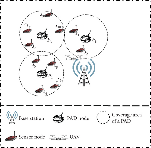
There are two alternative charging scheduling schemes in WRSN. With the on-demand charging scheme, the MC only recharges the nodes after receiving charging requests [19–22], whereas the periodic charging scheme instructs the MC to periodically recharge the sensor nodes along a specified path. The on-demand charging scheme is indeed more flexible and can reduce waiting times. However, it may not always be the most efficient solution. Periodic charging is a centralized charging strategy where the charging trajectory is calculated at the BS, and the MC moves along this predetermined path to execute the charging task. Since each node gets charged cyclically under the periodic charging scheme, the leftover energy of each node likewise varies regularly, ensuring that no node runs out of energy. Hence, periodic charging schemes typically function better than on-demand schemes, especially in situations where data loss cannot be tolerated. Moreover, the on-demand charging method does not ensure that every node will be charged since it is contingent on sensors providing explicit charging requests. This process of issuing requests inevitably leads to further energy expenditure.
Based on the above considerations, we investigate how to schedule the UAV to periodically charge the sensor nodes in a WRSN with PADs. In periodic charging, a charging cycle is the process of the MC leaving the BS to charge all nodes and then returning to the BS. The time required by a charging cycle is known as charging delay, and it is a crucial parameter for evaluating the performance of the periodic charging scheme. Therefore, we choose to minimize the charging delay as the optimization objective. We name our problem as the problem of periodic charging with minimum charging delay in a WRSN with PADs (PCMCDP). In this work, we first define and formalize the PCMCDP problem and prove that it is NP-hard. Then, we propose two periodic charging schemes to schedule the UAV to charge the sensor nodes. Simulations show that the proposed schemes achieve significant performance. To the best of our knowledge, our work is the first work on the periodical charging scheduling in WRSN with PADs.
The rest of the paper is organized as follows. Section 2 reviews the related work. Section 3 introduces the network model and formulates our problem. Section 4 presents the two proposed schemes. Section 5 conducts simulations for performance evaluation. Section 6 concludes our work.
2. Related Work
This section reviews existing studies relevant to our work. We first investigate previous studies on periodic charging scheduling in WRSNs. Then, we go through previous research on UAV-based WRSN. Finally, the PAD Technology section discusses the studies on PADs.
2.1. Periodic Charging Scheduling
In the existing periodic charging scheduling studies, the MC continuously charges each sensor node during periodic operation, subject to the network scenario. The factors that determine the network scenario include the geographical distribution of nodes, the energy consumption model of the network, and the movement speed of the MC. The majority of present research focuses on determining a node access sequence with varied optimization goals. As a result, these studies attempt to turn their objective problem into a traveling salesman problem (TSP) and schedule the MC via the shortest Hamilton cycle. For instance, Rao et al. [23] proposed a periodic charging scheme by scheduling the MC to move along the shortest Hamilton cycle to recharge each sensor node in order to minimize the total travel time of the MC. Xie et al. [24] investigated an optimization problem that jointly optimizes the traveling path, stopping points, charging schedule, and flow routing. The authors in [24] converted the problem into a solvable TSP and then constructed a Hamiltonian cycle as a feasible charging path for MC. Han et al. [8] proposed a cooperative charging algorithm for WRSNs based on network density clustering. The algorithm utilizes a mother wireless charging vehicle carrying multiple subwireless charging vehicles to periodically charge nodes in each cluster via a gradient descent optimization algorithm. Das, Dash, and Yadav [25] proposed GPCS, a GA-based periodic partial charging scheme for WRSNs, optimizing sensor charging with a battery-constrained MC. The scheme minimizes sensor dead periods and energy consumption, outperforming existing methods in charging efficiency and latency.
However, most of these efforts use wireless charging vehicles as MCs, which may not be suitable for difficult terrain.
2.2. Charging Scheduling With UAV
With the development of wireless charging technology for UAVs, many researchers have proposed using lightweight UAVs as an alternative approach for efficient and flexible charging in large scale or challenging scenarios in WRSNs.
The related work on UAV charging investigates optimizing the path planning and charging strategies for UAVs to maximize charging efficiency. Zhao et al. [26] investigated bridge monitoring task in 3D-WRSN by simulating the bridge and obstacles and proposed an optimized ant colony algorithm to solve the 3D UAV path planning problem with obstacles and then designed a two-phase algorithm to optimize the wireless charging at each time slot. In [27], an on-demand charging algorithm was proposed for the UAV charging in WRSN. This approach involved sensor clustering with K-means algorithm and cluster sorting using fuzzy logic. To address UAV path planning, a gradient-based optimizer (GBO) was employed. Lin et al. [28] proposed a spatial discretization scheme to obtain the set of UAV charging points and maximize the total charging energy. Wu et al. [10] studied the trajectory of the UAV optimization problem to maximize the energy utilization efficiency of the UAV. Liu et al. [11] proposed an improved particle swarm optimization (IPSO) algorithm that utilizes a flexible dimensional mechanism and the K-means operator to determine the hovering position of UAVs. Additionally, a penalty and compensation mechanism is used to resolve a scheduling optimization problem involving charging UAVs.
Due to the limitation of the UAV battery capacity, the coverage range of the UAV in the network scenario is limited. This means that providing charging services in ultra-large-scale WRSNs is difficult and introducing external charging devices for UAVs is a feasible solution.
2.3. PAD Technology
With the growing prevalence of UAVs, there is an increasing need for efficient and flexible charging solutions. In response, researchers have introduced the use of the PAD, which can wirelessly transmit energy to a hovering UAV using a pair of lightweight induction coils [13].
The introduction of PAD technology into WRSNs has received sufficient technical support, and several studies have focused on the deployment of PADs. Chen, Yu, and Ouyang [17] introduced PADs in a UAV-enabled WRSN so that UAVs with low residual energy could fly to nearby PADs for recharging. Four heuristic PAD deployment algorithms were proposed to reduce the number of PADs. However, Chen, Yu, and Ouyang [17] only considered the uniform distribution of central BS and nodes, making it unsuitable for large scale or challenging scenarios. Inspired by [17], Chen et al. [18] investigated the problem of deploying a minimum number of PADs in UAV-based WRSNs and proposed an adaptive PAD deployment scheme that can be applied to arbitrary locations of BSs, the arbitrary geographical distribution of sensor nodes, and arbitrary network areas.
Currently, there is a lack of extensive research on scheduling UAV charging in WRSNs. In this paper, building on the scheme and network deployment scenario proposed by [18], we further explore the UAV periodic charging scheduling problem.
3. Preliminaries
In this section, we first introduce the network model and the energy model. Then, we define and formalize the PCMCDP problem. Table 1 lists all the notations used in the paper. Additionally, Table A1 in the Appendix A presents all abbreviations used in this paper.
| Notation | Description |
|---|---|
| EUAV | Battery capacity of UAV |
| ES | Battery capacity of the sensor |
| VU | Flight speed of UAV |
| S | The set of sensor nodes |
| P′ | The set of charging stations |
| η | Energy transfer efficiency between UAV and sensors |
| Emov | Energy consumption during the movement of UAV |
| Ehov | Energy consumption of UAV hovering |
| Etravel | The sum of Emov and Ehov |
| Echarge | Energy consumption in the charging process of UAV |
| Erec | The energy obtained by the sensor |
| Phov | The hovering power of UAV |
| Pmov | The motion power of UAV |
| PPAD | The power for charging stations |
| tm | The flight time of the current charging cycle |
| th | The hovering time of the current charging cycle |
| Δ | The approximate time for UAV to charge each sensor |
| dmax | The maximum flight distance of the UAV |
| dcover | The charging coverage of UAV |
3.1. Network Model and Energy Model
We consider a large area with one BS, N static sensor nodes, a UAV, and M deployed PADs. Let S denotes the set of sensor nodes and P denotes the set of PADs. Since the BS, as well as the PADs, is capable of charging the UAV, they are sometimes collectively referred to as the charging stations in our work for the convenience of description. Let p0 denotes the BS and P′ = {p0, p1, p2, ⋯pm} denotes the set of charging stations. We also use pi ∈ P′ to denote the location of the PAD/BS. To simplify the problem, the energy supply of each charging station (the BS or a PAD) is unlimited.
Each sensor node si ∈ S is powered by a rechargeable battery with energy capacity ES and deployed statically on a given location (xi, yi) known by the BS and the UAV. The BS is also deployed arbitrarily according to the network requirement, and it is responsible for data gathering, charging schedule, and serving the UAV. The deployment of PADs satisfies the coverage constraint and the connectivity constraint simultaneously.
The UAV is also powered by a rechargeable battery with high capacity EUAV. The UAV flies at a constant speed VU between the sensor nodes, the PAD nodes, and the BS, and it must fly to one charging station for energy replenishment before the power runs out. Only the charging station (the BS or PADs) can charge the UAV, and the battery is fully charged when the UAV departs from the charging station. The procedure by which the UAV departs from the BS, charges all nodes once, and then returns to the BS is known as a charging cycle, and the time T taken for one charging cycle is referred to as charging delay.
3.2. Problem Definition
It is also to be noted that the coverage constraint and the connectivity constraint are the prerequisite assumptions of this paper. The two constraints need to be satisfied by the previous work [18], that is, the location of the PAD deployment of the network environment of this paper. The work in [18] is reviewed here and is not stated in the subsequent problem definition.
Based on the above analysis, the problem can be defined as follows:
Definition 1 (the PCMCDP). Given a monitoring area Ω, a BS p0, a UAV, a set of sensor nodes S = {s1, s2, ⋯, SN}, and a set of PADs P = {p1, p2, ⋯, pm}, the objective of our problem is to find the charging loop with the minimum charging delay that charges all the sensor nodes. This problem can be formulated as follows:
Equation (20) ensures that all possible subpaths cannot exceed the energy limit of the UAV, while Equations (21) and (22) ensure that all N sensor nodes are accessed by the UAV and only once. Equation (23) demonstrates the travel of the UAV starts and ends at the BS. Equation (24) guarantees that each sensor cannot die because the battery runs out.
Theorem 1. The PCMCDP is NP-hard.
Proof 1. According to the above mathematical model of the PCMCDP problem, if ignoring the energy limit of the UAV (Equation (20)), the UAV will not need to access any PAD for energy replenishment during the charging process. In this case, the PCMCDP problem becomes a problem to find a loop that minimizes T of traversing each sensor node from BS as the start and end point. According to Equation (17), if no PAD is accessed, T is directly proportional to the loop length. Therefore, if the energy limit of the UAV is ignored, the PCMCDP problem equals a standard TSP. Thus, the PCMCDP problem is the TSP with UAV energy limitation constraint. Since the TSP is NP-complete, we prove that the PCMCDP problem is NP-hard.
4. The Proposed Schemes
We have analyzed and formalized the PCMCDP problem so far. In this section, we present two algorithms to solve the PCMCDP problem, namely, sensor-node-based charging (SNBC) and PAD-based charging (PBC), respectively.
4.1. SNBC Scheme
The SNBC scheme finds the charging path from the perspective of sensor nodes.
According to the above analysis, the PCMCDP problem is essentially a TSP with the UAV energy limit constraint. Therefore, the basic idea of SNBC is pretty straight. The SNBC algorithm first creates a Hamiltonian loop for all the sensor nodes to be charged, then checks whether the loop satisfies the energy constraint of the UAV, inserts the charging stations into the loop, and finally obtains the charging path of the UAV.
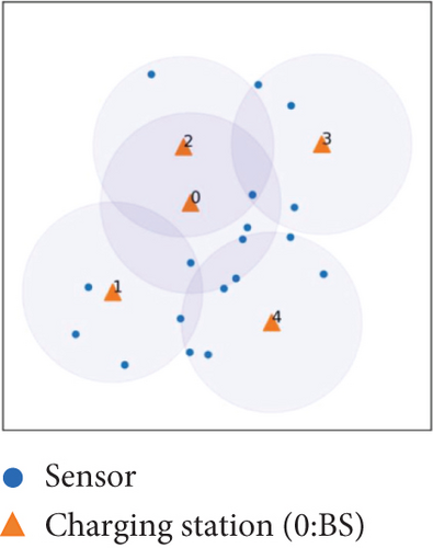
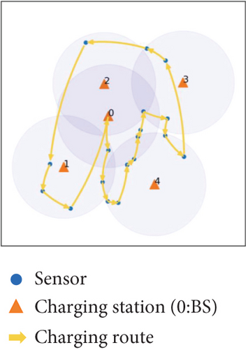
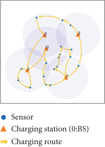
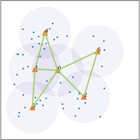
Figure 2(a) presents a diagram of the initial network environment for SNBC scheme, illustrating the deployment locations of the charging stations and sensors, as well as the coverage area of the charging stations. We first ignore the UAV energy limit constraint and get the shortest distance Hamiltonian cycle including all the sensors and the BS by the LKH algorithm [31]. This Hamiltonian cycle can be represented as a sequence , where s′i ∈ S represents the ith sensor node in this cycle. To easily illuminate our algorithm, with an element m in the sequence Seq, let PRE(m) and SUCC(m) denote the predecessor and the successor of m, respectively. This process is depicted in Figure 2(b).
In Equation (25), we still use the node battery capacity instead of the energy that the node needs to replenish for simplicity.
Without losing generality, we use the node battery capacity instead of the energy that the node needs to replenish for simplicity in Equation (27).
If Equation (27) cannot be met, we find the shortest path from pj to P(SUCC(pj)) from the connected graph G which only includes charging stations, get all the charging stations in this path except pj, and insert them between pj and SUCC(pj), corresponding to Lines 7 and 8 in Algorithm 1. We perform this energy limitation check not only for the charging stations that are postinserted in the sequence but also for p0, to avoid the BS being in a very remote location, and the UAV could not charge from p0, corresponding to Lines 2 and 3 in Algorithm 1.
After checking the energy limitation of all the elements in Seq, we get the charging cycle of the UAV. The process is presented in Figure 2(c), and the details of the SNBC algorithm are depicted in Algorithm 1.
-
Algorithm 1: SNBC scheme.
-
Input: charging stations set P′, sensor nodes set S, UAV
-
Output: the cruise path of UAV Seq
-
1 Seq ⟵ LKH({p0, S}) //obtain the shortest path of
-
sensors
-
2 if UAV cannot cruise from p0 to by checking Eq 27
-
then
-
3 insert shortest path only including charging
-
stations (p0,) between p0 and in Seq
-
4 for i ⟵1 to N − 1do
-
5 if UAV cannot satisfy energy constraint Eq 25 then
-
6 insert into Seq after the node
-
7 if not satisfy the constraint Eq 27
-
then
-
8 insert shortest path only including
-
charging stations () between
-
and in Seq
-
9 if UAV cannot cruise from to p0 by checking Eq 28
-
then
-
10 insert shortest path only including charging
-
stations () between and p0 in Seq
-
11 return Seq
4.2. PBC Scheme
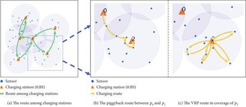
Recalling the coverage and connectivity constraints for the deployment of PADs described in the Problem Definition section, all the sensor nodes are covered by charging stations, and the charging stations are connected. The UAV can charge any sensor node si from the charging station P(si). Based on the above consideration, we propose a PBC scheme, which builds the charging path based on PADs. PBC first creates a loop that visits all PADs from the BS and returns to the BS. Consequently, the UAV moves according to this loop. When the UAV arrives at a charging station, it can charge the sensor nodes covered by that charging station. It is noted that if the two charging stations are relatively close, the UAV may have enough energy to charge certain sensor nodes while flying from one charging station to the other. In PBC, we call that these nodes can be piggyback-charged. As a result, the PBC scheme is divided into three steps: first, building a loop based on charging stations, then determining the piggyback-charged nodes, and finally for each charging station, determining the charging path for the uncharged nodes it covers. The process of PBC scheme is diagrammed in Figure 3.
Designing a circuit that encompasses all charging stations resembles a TSP. However, although we already have the connected graph of charging stations G, there is no guarantee that G is a Hamiltonian graph. As a result, we can not use any TSP algorithm to build the loop based on charging stations directly. But we can get our loop based on the result of the TSP algorithm.
We construct an auxiliary weighted complete graph G′ = (P′, E′) based on G = (P′, E) as Figure 4. To construct the complete graph, we first add E into E′. Then, we check, for a charging station pi, whether the edge (pi, pj) ∈ E, i ≠ j. If not, we add (pi, pj) into E′ and find the shortest path shortestpath(pi, pj) from pi to pj in G and the weight of (pi, pj) ∈ E′ is set as the length of shortestpath(pi, pj). After completing this operation for all the charging stations, we get the weighted complete graph G′, corresponding to Line 1 to Line 9 in Algorithm 2.
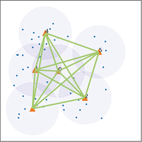
Then, we can run the LKH algorithm on G′ to get a minimum weighted Hamiltonian cycle that starts and ends at p0. We check each edge (pj, SUCC(pj)), j = 0, ⋯, M. If (pj, SUCC(pj)) ∉ E, we replace this edge with shortestpath(pj, SUCC(pj)). In this way, we can get the minimum cycle including all the charging stations, corresponding to Line 10 to Line 13 in Algorithm 2.
After obtaining the charging loop including all charging stations, we get the order of accessing all charging stations for the UAV. We now need to determine which sensor nodes can be piggyback-charged as the UAV flies from one charging station to its successor charging station.
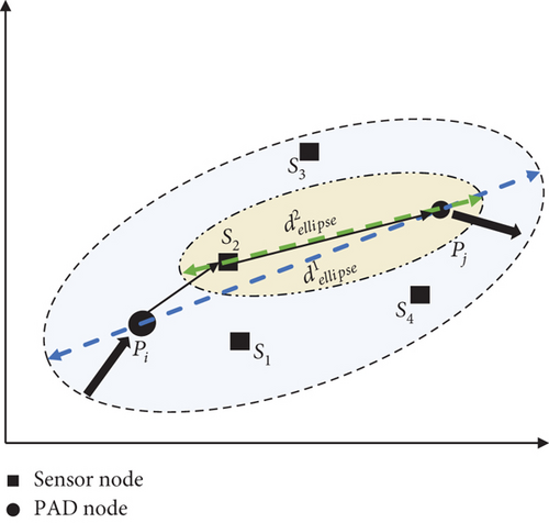
Since the UAV leaves pi with full energy, erem = EUAV in this case. Obviously, according to the property of the ellipse, the UAV has enough energy to charge any sensor node located in this ellipse from pi before flying to pj. If there are multiple sensor nodes in this ellipse, we select the node st with the closest distance to pi as the piggyback-charged node. Then, we try to build another ellipse to find the next piggyback-charged node, where st and pj as the focal points and the long axis is determined by Equation (29) in which erem is the remaining energy of UAV after charging st. And we check whether the ellipse can be formed, by observing whether the long axis dellipse is more than the focal length. If so, we can repeat the above steps until there are no sensor nodes in the newly constructed ellipse, corresponding to Line 14 to Line 23 in Algorithm 2. Then, we add the selected piggyback-charged nodes into a sequence seqi,j. Figure 5 illuminates the steps to select the piggyback-charged nodes in (pi, pj).
We can get all the piggyback-charged nodes by applying the above operation to all segments in the charging loop.
When reaching a charging station pj, the UAV can charge the remaining nodes except the piggyback-charged nodes . According to [32], the problem to schedule the UAV to charge the nodes in C(pj) from pj is essentially a vehicle routing problem (VRP). We solve this problem by introducing a genetic algorithm similar to [33] and obtaining the charging path of the UAV, corresponding to Line 24 to Line 27 in Algorithm 2. Figure 3(c) shows the route for in p2’s coverage.
The details of the PBC scheme are depicted in Algorithm 2.
-
Algorithm 2: PAD-based charging scheme.
-
Input: charging stations set P′, sensor nodes set S, UAV
-
Output: the charging path of UAV Path
-
1 construct the connected graph G = (P′, E)
-
2 //construct the complete graph G′ = (P′, E′) based on G = (P′, E)
-
3 add E into E′
-
4 for PAD pi in P′do
-
5 for PAD pj in P′\{pi}do
-
6 if edge (pi, pj) not in E then
-
7 add (pi, pj) into E′
-
8 find shortestpath(pi, pj) in G
-
9 the weight of (pi, pj)⟵the length of shortestpath(pi, pj)
-
10 Path⟵LKH(G′)
-
11 for pj in Pathdo
-
12 if (pj, SUCC(pj)) not in Ethen
-
13 replace (pj, SUCC(pj)) with shortestpath(pj, SUCC(pj))
-
14 for pi in Pathdo
-
15 startNode⟵pi
-
16 calculate dellipse according to Eq 29
-
17 construct Ellipse(startNode,SUCC(pi),dellipse)
-
18 while the ellipse cover new nodes do
-
19 st ⟵the nearest node of startNode
-
20 if UAV cannot fly to SUCC(pi) after charging stthen
-
21 break
-
22 insert st to Path
-
23 startNode⟵st
-
24 for pi in P′do
-
25 C(pi) -
-
26 ⟵ GA()
-
27 insert into Path
-
28 return Path
5. Experimental Simulation and Analysis
In this section, we evaluate the performance of the two proposed schemes. To illustrate the effectiveness of our proposed scheme, we conduct three groups of simulations by varying the number of sensor nodes, the size of the network region, and the UAV battery capacity. We only compare the performance of the two proposed schemes because this is the first work on periodic charge scheduling schemes in UAV-based WRSN with PADs and there is no baseline to compare with. We use two performance metrics: the charging delay and the times of replenishment at charging stations. The charging delay is our optimization goal and the most essential metric in periodic charging scheduling, which indicates the highest energy consumption rate of nodes that the periodic charging scheduling algorithm can handle. The times of replenishment at charging stations is the total number of times the UAV gets charged at charging stations during the whole charging cycle. Obviously, the fewer times the UAV is charged at a single charging station during a charging cycle represents a smaller total energy consumption of the charging cycle, which means a higher charging efficiency.
In each simulation, static rechargeable sensor nodes are deployed randomly over a square area. The BS is located at the center of the region. We run the PAD deployment algorithm in [18] first to generate the locations of PADs. The parameters of PADs are set according to the PAD model presented in the literature [34]. In addition, we use the energy consumption model and the energy charging model introduced in [30]. We use the average results of 10 sets of data to smooth the data for each simulation. The default parameters used in the simulations are listed in Table 2.
5.1. Impact of the Number of Sensor Nodes
Figure 6 depicts the simulation results of changing the number of nodes from 50 to 500. According to [18], changing the number of nodes has approximately no effect on the number of deployed PADs because the number of PADs is determined mostly by the UAV’s coverage radius and network size, with node density having a minor impact.
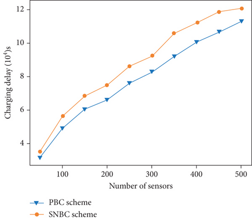
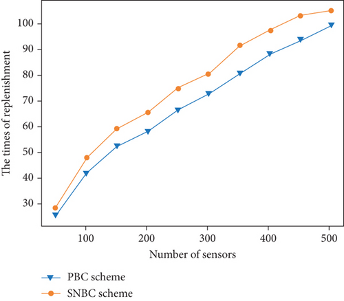
As expected, for the two schemes, the charging delay and the times of replenishment at charging stations increase as the number of sensor nodes increases. It is natural that more nodes need to be charged in one charging cycle as the number of nodes increases. As a result, the flight distance of the UAV in one charging cycle must also increase, which triggers the charging delay and the times of replenishment at charging stations grow. We notice that the PBC scheme outperforms the SNBC scheme on both performance metrics. This is because in the SNBC scheme, the UAV is scheduled to charge the sensor nodes along a TSP path of sensor nodes and then fly to charging stations for energy replenishment if the energy constraint is not met. Meanwhile, the PBC scheme creates a charging loop of charging stations so that the UAV can piggyback charge a portion of the sensor nodes as it flies from one charging station to the next and charge the remainder of the nodes from charging stations that cover them with a VRP algorithm. In other words, the SNBC scheme only optimizes the travel between sensor nodes, while the PBC scheme optimizes the travel between charging stations, between charging stations and nodes, and between nodes.
5.2. Impact of Regional Scale
Figure 7 shows the simulation results of varying the size of the network area from 12,000 m × 12,000 m to 21,000 m × 21,000 m. Different from varying the number of nodes, varying the size of the network causes varying PAD deployment. The larger the network area, the more PADs need to be deployed to ensure connectivity constraint and coverage constraint.
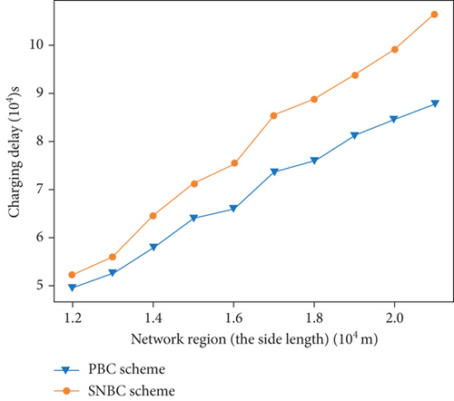
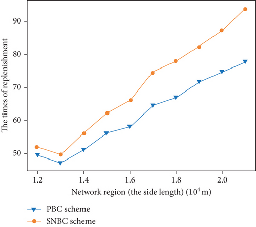
According to Figure 7, as the network area grows, so do the charging delay and the times of replenishment at charging stations. This is due to the fact that the density of nodes decreases as the network area grows. As a result, the UAV must fly greater distances to charge a specific node in a network with a larger area. Still, we can find that the PBC scheme achieves a better performance than the SNBC scheme. We can conclude a similar conclusion with Figure 6. The SNBC scheme only optimizes the travel between sensor nodes, while the PBC scheme optimizes the whole charging path. This conclusion is supported by Figure 7, which shows that as the network area grows, the performance advantage of PBC over SNBC grows.
5.3. Impact of UAV Energy
We varied the battery capacity of the UAV in this simulation, and Figure 8 shows the simulation results of changing the UAV battery capacity from 64,000 to 82,000 J. As the capacity of the UAV battery increases, the two evaluation metrics perform differently for the two schemes.
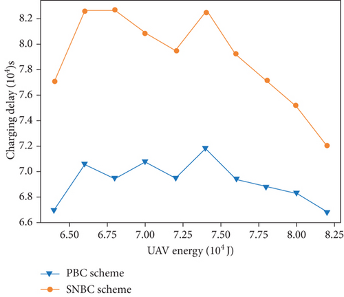
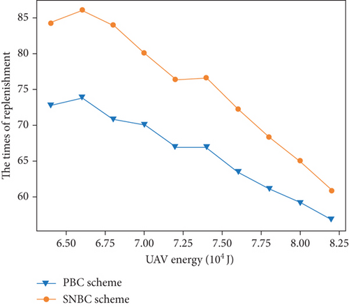
From Figure 8(a), the charging delay of the two schemes oscillates, although a downward trend is visible in some intervals. This is because the UAV battery capacity determines the maximum flight distance dmax and the coverage range dcover of the UAV. The larger the UAV battery capacity, the larger dmax and dcover become. According to Equations (9) and (12), due to the connectivity constraint and the coverage constraint, the coverage range of charging stations increases as dcover grows, and the maximum distance between two adjacent charging stations increases as dmax grows. Consequently, the number of deployed PADs reduces as the UAV battery capacity increases, which explains the down trends of the charging delay in some intervals. On the other hand, as the UAV battery capacity increases, the time required to recharge the UAV at charging stations also increases, leading to an increase in the charging delay, which can result in oscillations. Figure 8(b) depicts how the times of replenishment at charging stations for the two approaches reduce as the UAV battery capacity increases. This is to state that the more energy the UAV can carry, the more nodes it can charge in a single flight. As a result, the frequency with which the UAV visits charging stations for battery replenishment lowers. Still, we notice that the PBC scheme outperforms the SNBC scheme.
5.4. Result Discussion
In the above simulations, we can make a comparison table of the results of the PBC algorithm and SNBC algorithm as Tables 3 and 4. The average charging delay and the average number of returns to the charging station for charging are shown for PBC and SNBC in different network scenarios.
| Varying nodes | Varying regions | Varying EUAV | |
|---|---|---|---|
| PBC | 7.778 | 6.933 | 6.918 |
| SNBC | 8.725 | 7.935 | 7.890 |
| Varying nodes | Varying regions | Varying EUAV | |
|---|---|---|---|
| PBC | 67.79 | 61.74 | 66.20 |
| SNBC | 75.45 | 70.18 | 75.40 |
In the scenario of varying number of sensor nodes, the PBC algorithm reduces charging delay by 12.57% on average and the times of replenishment by 11.87% on average compared to the SNBC algorithm. In the scenario of varying regional scale, the PBC algorithm reduces charging delay by 13.64% on average and the times of replenishment by 12.90% on average compared to the SNBC algorithm. In the scenario of varying UAV energy, the PBC algorithm reduces charging delay by 14.01% on average and the times of replenishment by 13.66% on average compared to the SNBC algorithm.
These results demonstrate that in multiple scenarios, the PBC algorithm outperforms the SNBC algorithm, significantly improving network efficiency, extending network lifespan, and reducing energy wastage. However, it is crucial to note that in cases with ample UAV battery capacity, small network regions, and limited number of sensor nodes, the SNBC algorithm still performs acceptably and is particularly suitable for these specific conditions.
We delve into the performance of our algorithm and evaluate it based on two key metrics: the charging delay and the times of replenishment. The charging delay represents the shortest time interval between two consecutive charges of a node and indicates the node’s maximum energy consumption rate that our charging scheduling algorithms allow. In the meanwhile, the times of replenishment at charging stations can be roughly extrapolated to the total energy used by the UAV during a charging cycle, which in turn can be used to calculate the charging efficiency during a charging cycle.
According to Equations (30) and (31), the values of the max tolerable energy consumption rate of the sensors ρmax and the charging efficiency of the network eff can be calculated for different scenarios. Figure 9 illustrates the results of ρmax and eff in scenarios with various numbers of sensors. As the number of sensors expands, both the tolerable energy consumption of the sensor and network efficiency decrease. The decline in ρmax is primarily attributed to the increasing charging delay, which grows with the greater number of sensors. According to Equation (31), we can observe that eff is influenced by two parameters: the number of sensor nodes and the return times for UAV replenishment. By observing Figure 6(b), it is evident that the rate of increase in the return times is smaller than the rate of increase in the number of sensor nodes. Hence, eff increases with the growth in the number of sensor nodes. On average, the PBC algorithm exhibits a 15.60% increase in ρmax and a 15.02% improvement in eff when compared to the SNBC algorithm.
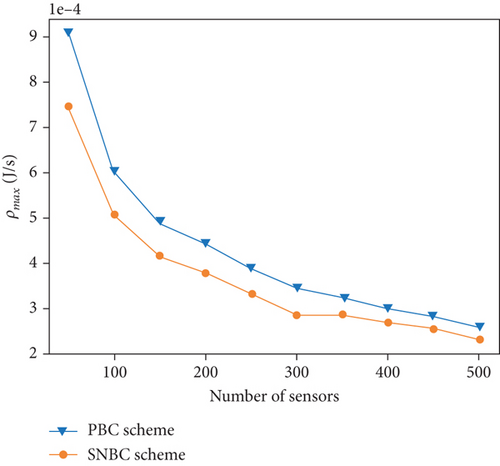
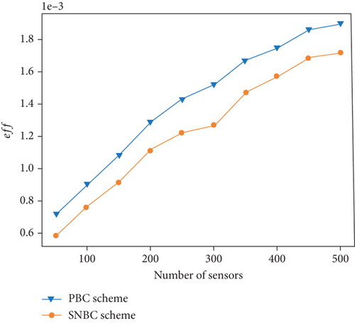
Figure 10 illustrates the results of ρmax and eff in various region sizes. As the network region expands, both the tolerable energy consumption of the sensor and network efficiency decrease. The decline in ρmax is primarily attributed to the increasing charging delay, which grows with the larger network region. Similarly, the reduction in eff is predominantly due to the increasing number of return times for the UAV, which also escalates with the larger network region. On average, the PBC algorithm exhibits a 15.91% increase in ρmax and a 15.62% improvement in eff when compared to the SNBC algorithm.
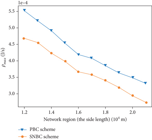
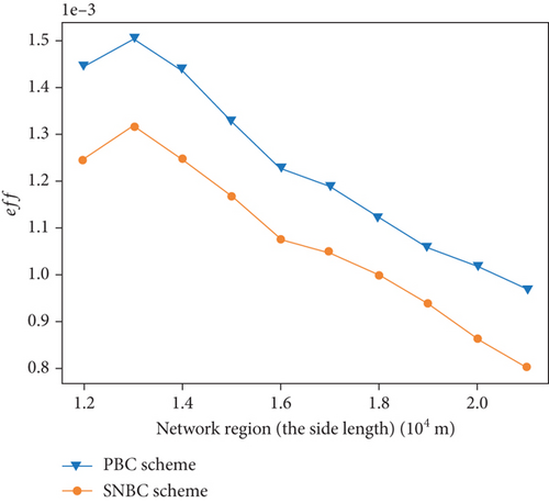
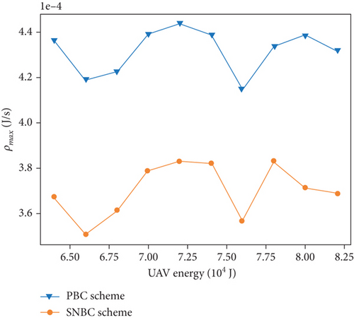
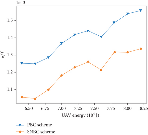
Figure 11 illustrates the results of ρmax and eff in scenarios with various UAV energy capabilities EUAV. As the energy of UAV EUAV increases, the tolerable energy consumption of the sensor oscillates and network efficiency increase. The oscillation in ρmax is primarily attributed to the charging delay shown in Figure 8(a). The reason of oscillation of charging delay has been discussed before. According to Equation (31), eff is influenced by the UAV’s energy and the return times for UAV replenishment, with the fixed number of sensor nodes. By examining Figure 8(b), it becomes evident that the rate of decrease in the return times for UAV replenishment is greater than the rate of increase in the UAV’s energy. This overall trend results in an upward trajectory for eff. On average, the PBC algorithm exhibits a 16.60% increase in ρmax and a 16.32% improvement in eff when compared to the SNBC algorithm.
It is evident that PBC excels in terms of network efficiency and demonstrates a high tolerance for sensor energy consumption. However, it is worth noting that the results achieved by SNBC remain within an acceptable range.
6. Conclusion
The application of UAV in WRSN holds great promise. Building on our previous work [18] on PAD deployment schemes, this paper further studies the problem of periodic charging with minimal charging delay in a WRSN with PADs and proposes two schemes from two different perspectives: the SNBC scheme and the PBC scheme.
In the SNBC scheme, we schedule the UAV to charge the sensors along a TSP path of sensor nodes and fly to charging stations for energy replenishment once the energy constraint is not satisfied. In the PBC scheme, we construct the PAD-based route of the UAV for charging the sensors. Initially, the UAV moves along the loop of PADs. Additionally, we introduce a piggyback scheme to charge part of sensor nodes along the movement between two adjacent PADs. Then, we employ a genetic algorithm to charge the remaining sensors covered by each PAD except the piggyback-charged nodes. Simulation results demonstrate that our two proposed schemes are feasible and the PBC scheme performs better than the SNBC scheme in terms of charging delay and total travel distance, particularly in a large scale of WRSN. To the best of our knowledge, this is the first study to address the periodic charging scheduling problem in a UAV-based WRSN with PADs, offering new insights into this area.
It is noted that all periodic charging algorithms, including our work, have an inherent disadvantage. Once the node charging sequence is established by a periodic charging algorithm, the MC (UAV) recharges nodes in the same order during each cycle, failing to adapt to fluctuations in node energy consumption rates and limiting the maximum energy consumption rate of the network’s nodes. In contrast, on-demand charging algorithms dynamically select energy-depleted nodes for recharging based on their energy status, offering better adaptability to variations in energy consumption. Additionally, our proposed periodic charging algorithms only consider the deployment of a single UAV. The simultaneous charging by multiple UAVs could reduce charging delays, enhance efficiency, and expand the network’s monitoring area. However, coordinating multiple UAVs in a WRSN introduces a new challenge. We are dedicated to exploring the integration of periodic partial charging to improve energy efficiency and sustainability in WRSNs. We will also investigate the synergistic effects of combining energy harvesting technologies, such as solar power, with wireless energy transfer to establish a more resilient and eco-friendly charging ecosystem.
Moving forward, our future research will address on-demand charging, multi-UAV collaboration, and partial charging, integrating hybrid energy harvesting techniques to dynamically optimize energy distribution for efficient and sustainable network operation.
Conflicts of Interest
The authors declare no conflicts of interest.
Funding
This work is supported by Sichuan Science and Technology Program (grant no. 2022YFQ0035).
Appendix A
| Abbreviation | Definition |
|---|---|
| Wireless rechargeable sensor network | WRSN |
| Internet of Things | IoT |
| Wireless sensor network | WSN |
| Unmanned aerial vehicle | UAV |
| Automatic landing pad | PAD |
| Sensor-node-based charging | SNBC |
| PAD-based charging | PBC |
| Wireless power transfer | WPT |
| Clustering-with-double-constraints and disks-shift-combining | CDC&DSC |
| Base station | BS |
| Mobile charger | MC |
| The Problem of Periodic Charging with Minimum Charging Delay in a WRSN with PADs | PCMCDP |
| Traveling Salesman Problem | TSP |
| Vehicle routing problem | VRP |
Open Research
Data Availability Statement
The data that support the findings of this study are not publicly available due to privacy concerns. Data are however available from the authors upon reasonable request.


