Research on the Simulation Method for Equivalent Stiffness of Bolted Connection Thin Plate Structures
Abstract
Bolted connections are widely used in assembly structures, and their dynamic characteristics are often affected by stiffness, damping, excitation, and other factors. In order to solve the problems of low computational efficiency of fine modeling and large computational error of linearized equivalent modeling of bolted structures, this paper proposes a dynamic characteristic parameter identification method for bolted structures based on the multiscale method and considering the influence of nonlinear factors. In this method, the bolted connection characteristics are simulated in the form of a combination of shear stiffness, torsional stiffness, nonlinear stiffness, and viscous damping coefficient and identified according to the test measurement frequency and frequency response function. At the same time, by establishing the nonlinear dynamic model of bolted structure, the influence of different bolt preloads and excitation forces on the dynamic characteristics of bolted structure is studied.
1. Introduction
Bolted joints are widely used in assembled structures, where the dynamics are often influenced by various factors such as stiffness, damping, and excitation, making direct measurement of the relevant parameters very difficult [1, 2]. For example, the bolt joint surface can cause local stiffness and damping discontinuities in the structure, and the contact stiffness resulting from nonlinear contact on the bolt joint surface will also directly affect the mechanical properties of the bolt joint structure. In addition, the analytical solution for contact stiffness is often difficult to obtain or has considerable uncertainty due to factors such as contact surface area, coefficient of friction, and roughness. On the other hand, in practical engineering calculations, a certain degree of dynamical simplification or linear equivalence is usually applied to the bolt joints, and this treatment ignores the nonlinear nature of the bolt joints and fails to describe the complex nonlinear phenomena caused by the presence of the joint interface.
In the early stage, the dynamic model of the whole machine structure was composed of simple beams, bars, and plates due to the limitation of computational capacity, and the whole machine structure model only included hundreds of degrees of freedom [3]. At this stage, the dynamic model calculation results depend on the experience of the modeler, and a lot of simplification needs to be introduced in the modeling process. The established model can only roughly reflect the overall dynamic characteristics of the structure and cannot directly analyze the local deformation or dynamic stress state of the structure through the whole machine model. In addition, the calculation accuracy of the model is not satisfactory because of the introduction of a large number of simplified assumptions.
With the development of computer performance and finite element technology, dynamic modeling technology has entered the stage of fine modeling. With very detailed finite element models, researchers can obtain highly accurate calculation results, such as stress analysis, modal characteristics. However, the calculation scale of the refined model is relatively large. For the part-level structure, it is feasible to accurately determine the mechanical properties of the part structure through this refined model. For the assembly-level structure with many parts, if the refined model is adopted, the calculation cost is still very high. Therefore, from the perspective of considering the calculation accuracy and efficiency of the model, the basic stressed structure should be properly simplified while retaining its main mechanical characteristics, which can not only meet the requirements of high-precision calculation but also control the overall model calculation scale within a reasonable range.
In general, when dealing with dynamic problems with connected structures, the commonly used method is based on the linearization idea, ignoring the connection or equivalent connection to the combination of linear spring and linear damping unit, and then using model modification, test identification, and other methods to give the parameters of the spring units and damping units. There are mainly two ways to achieve this. One is to identify the damping matrix and stiffness matrix of the connection part by using the substructure method and using the modal parameter identification method, combining the modal data or frequency response function before and after installation [4]. However, it is difficult to accurately measure the frequency response function, especially when it involves the degree of freedom of rotation. Measuring noise level is also one of the important standards to measure the recognition effect of this method, and how to reduce the error caused by environmental noise is also a difficulty of this method [5]. The other method is to simulate the connection relationship of connection parts by equivalent elements. Ahmadian et al. [6] simulates the connection of the joint surface by constructing a hexahedral isoperimetric solid element and identifying the elastic modulus and shear modulus of the element to obtain the equivalent stiffness of the connection. Kuanmi et al. [7] proposed a general form of connection element for bolted connection structures, considering the coupling between each degree of freedom of the joint surface and the connection structure, and carried out experimental verification. The experimental results show the effectiveness and reliability of this method, and the error between the identified model calculation results and the experimental results is within 10% [8]. However, this linearized equivalence ignores the nonlinear characteristics of the connection and simply simulates the effects of complex viscous sliding and clearance collision with linearized stiffness and damping, which makes this method must be based on tests and cannot meet the requirements of dynamic calculation and analysis for design. In fact, in the actual structure, most of the joint structures will show nonlinear characteristics, so it is important to study the nonlinear dynamic modeling of the joint structures. Jalali et al. [9] considered the nonlinear characteristics of the bolted interface, deduced the dynamic differential equation of the element, and used the force state mapping method to identify the mechanical property parameters of the nonlinear interface. By analogy to the linear equivalent element method, some scholars introduced nonlinear materials to simulate the nonlinear characteristics of nonlinear joint surfaces. Iranzad and Ahmadian [10] introduced elastic-plastic materials to simulate the microslip and transverse macroslip phenomena that may occur on the bolt joint surface and established the dynamic model of the joint surface using the QUAD4 element. By identifying the hardening modulus, linear modulus, yield stress, and other parameters of elastoplastic materials, the joint surface of the bolt structure can be identified. Mayer and Gaul [11] introduced the Masing damping model which can describe plastic sliding stiffness and stuck linear stiffness, used a zero-thickness contact element to simulate microsliding effect and friction in bolts, and took a specific bolt installation structure as an example to verify that the proposed connection model can well simulate the nonlinear stiffness and damping characteristics caused by bolt connection.
In this manuscript, a linearized equivalence method for the stiffness of bolted joints and an equivalence calculation method that considers nonlinear influences are proposed. Firstly, the calculation method of nonlinear contact is introduced. Secondly, the linear equivalent of bolt connection stiffness and the equivalent calculation method considering nonlinear influence factors are given, respectively. Finally, the accuracy of the two equivalent methods and their influence on the calculation accuracy are compared through numerical simulation examples.
2. Linearized Equivalent Modelling and Stiffness Calculation Method for Bolted Joint Structures
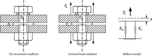
Depending on the different engineering and computational requirements, there are three main methods of linearized modelling of bolted joint structures in common: the virtual material method, the multipoint constraint method, and the spring damping method. In this manuscript, the spring damping method is mainly investigated.
When using the spring damping method to simulate bolted joints, realistic and reliable stiffness and damping inputs are the key to accurate simulation. Due to the fact that the bolts themselves are usually made of alloy steel and the form of assembly in the actual structure, the influence of damping is normally unconsidered.
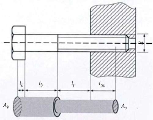
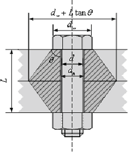
According to the mechanical design manual, the calculation of the bolt’s own stiffness can be simplified in the form of Figure 2.
3. Parameter Identification of Bolted Joint Structures considering Nonlinear Factors
3.1. Nonlinear Model for Bolted Beam Structures
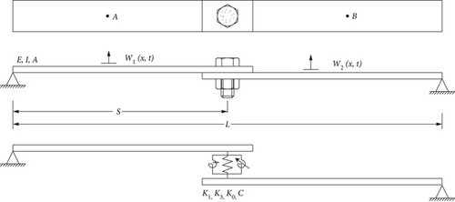
Considering the bolted beam structure shown in Figure 4, consisting of two identical linear Euler-Bernoulli beams bolted together, with the bolted beam combination is solidly supported at both ends. Where Kl and Kθ denote the linear shear and torsional stiffnesses, respectively, K3 denotes the cubic stiffness term, and C denotes the viscous damping factor at the joint. In this manuscript, the nonlinear spring is used to simulate the nonlinear characteristics of the contact interface under the preload of the bolts.
3.2. Analytical Solution of Bolted Joint Beams Based on Multiscale Method
Substituting the linear analytical expressions (14) and (15) into Equation (6)–Equation (13) and separating the ε0 and ε3 terms, the differential equations of motion, boundary conditions, and continuity conditions at different time scales can be obtained for the main resonant state near the first order intrinsic frequency.
3.2.1. ε0-Order Term
3.2.2. ε3-Order Term
3.2.3. The First-Order Resonant Response of the ε0-Order Term Homogeneous Equation
3.2.4. The Solutions of Nonhomogeneous Equations of ε3-Order Term
In this manuscript, the frequency of the external excitation Ω is assumed to be close to the first order natural frequency ω of the structure, i.e., Ω = ω + ε2σ. where σ denotes the simple harmonic parameter and ε is the minor parameter.
According to the expansion theorem and the regularization condition, the approximate perturbation solutions of eigenvectors and eigenvalues can be obtained. This method has strong advantages in terms of computational speed and solution accuracy in engineering applications.
4. Numerical Validation of Equivalent Stiffness Modelling Methods for Bolted Joint Structures
In finite element analysis, contact conditions are a special type of discontinuous constraint that allows forces to be transmitted from one part of the model to another. When two surfaces come into contact, contact forces are generated. When the two surfaces separate, there is no constraint, making this constraint type discontinuous. Contact problems are highly nonlinear behaviors that require not only a significant amount of computational resources but also pose considerable difficulties during the modeling and assumption phase. In general, fundamental contact issues mainly focus on two aspects: firstly, the determination of the contact area, and secondly, the determination of frictional forces during contact.
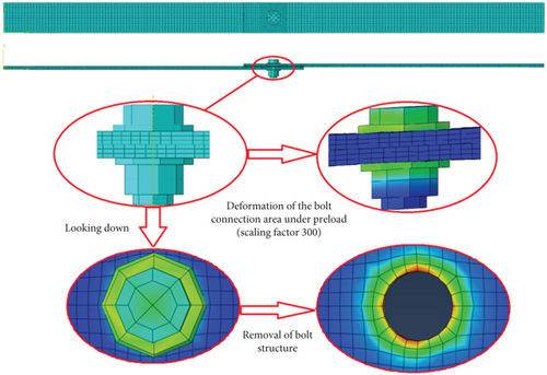
In order to further illustrate the influence of traditional linear equivalent simulation and equivalent simulation considering nonlinear factors on the accuracy of simulation calculation in the process of finite element modelling calculation of bolted structure, this manuscript adopts ABAQUS, which is a finite element simulation analysis software with strong ability to deal with nonlinear problems, to carry out finite element modelling simulation calculation of bolted joint beam structure and simulate the real dynamic test results of the structure, the finite element model is shown in Figure 5. The bolted beam structure was fixed at both ends, and the nonlinear contact of the bolts was simulated by defining the friction coefficient and contact stiffness on each contact surface of the structure. The finite element model is modelled using the uncoordinated mode of the 8-node C3D8 3D stress cell, which on the one hand can accurately simulate the contact stresses and contact deformations at the bolt bond area and on the other hand can overcome the problem of scattered calculations due to shear locking of fully integrated first-order cells. In addition, in order to make the ABAQUS simulation calculation results more realistic simulation of the dynamics test, this manuscript adds 5% white noise to the simulation calculation results to simulate the real test results, and the test measurement frequency as shown in Table 1.
| Order | 1 | 2 | 3 | 4 |
|---|---|---|---|---|
| Frequency (Hz) | 20.629 | 79.812 | 125.06 | 232.15 |
4.1. Linearized Modelling Simulation and Equivalent Stiffness Calculation
Due to the solid meshes, nonlinear contact algorithms, and other factors, the ABAQUS-based finite element model described above is time-consuming and computationally inefficient. In order to improve calculation efficiency, beam units and shell units are usually used to simulate bolted coupling beams, and connection units are used to simulate bolts in practice. Then, in this part, the shell unit is used to simulate the bolted coupling beam, and the connection unit is used to simulate the bolts. The finite element model is shown in Figure 6.

The beam parameters are known as modulus of elasticity E = 70 Gpa, length l = 0.5 m, bolt position S = 0.45 m, density ρ = 2710 kg/m3, mass per unit length m = 0.542 kg/m, and moment of inertia I = 2.67 × 10⁻¹⁰ m4. The bolts are standard hexagonal bolts of M12 and the nuts are standard hexagonal nuts of M12, and the parameters are known as modulus of elasticity E = 209 Gpa and density ρ = 7890 kg/m3.
Substituting the geometric parameters of the bolt and the bolted coupling beam into Equation (2)–Equation (5), the equivalent stiffness of the linearized bolt is calculated as 1.1015 × 10⁹ N/m. The first 4 orders of natural frequencies of the structure are calculated based on the FEM numerical simulation software and are shown in Table 2.
| Order | 1 | 2 | 3 | 4 |
|---|---|---|---|---|
| Natural frequency (Hz) | 23.082 | 81.378 | 129.38 | 239.11 |
| Errors | 11.89% | 1.96% | 3.45% | 3.00% |
As we can see from the comparison in Table 2, the equivalent stiffness values obtained by the linearized equivalence method are larger and correspond to a completely rigid connection to the structure, which does not correspond to the actual structural connection. And the resulting calculated intrinsic frequencies of each order are greater than the experimental measurements, especially the first-order frequency error of about 12%. Since in engineering we tend to be more concerned with the lower-order modalities of a structure, obtaining a finite element model by linearized equivalence is not suitable for practical engineering.
4.2. Modelling Simulation and Equivalent Stiffness Calculation considering Nonlinear Factors
As linearized equivalence would lead to overly rigid structures with large frequencies, the effect of nonlinear factors needs to be considered to realistically and accurately simulate the bolted joint. In this manuscript, the modal analysis of the structure is carried out by applying a random excitation at the position of point A shown in Figure 7 and measuring the linear frequency response of the bolted beam structure at the position of point B to obtain the first four orders of linear natural frequencies of the structure. According to the strength limits of the bolts in the mechanical design manual, the modal frequencies of the structure were calculated for four working conditions, namely, 1 KN, 2.5 KN, 5 KN, and 10 KN for the preload force of the bolts. The curves of the linear frequency response function at point B for these four operating conditions are shown in Figure 7, and the frequency values corresponding to the first four resonance peaks of the linear frequency response function of the bolted beam for these four operating conditions are shown in Table 3.
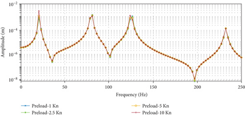
| Linear natural frequency (Hz) | |||||
|---|---|---|---|---|---|
| First order | Second order | Third order | Firth order | ||
| Bolt preloads (KN) | 1 | 20.929 | 79.824 | 125.26 | 232.53 |
| 2.5 | 20.865 | 79.795 | 125.17 | 232.46 | |
| 5 | 20.758 | 79.747 | 125.00 | 232.35 | |
| 10 | 20.545 | 79.656 | 124.68 | 232.12 | |
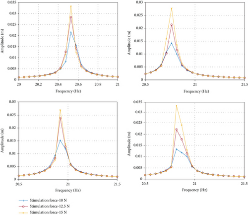
Figure 8 shows the displacement frequency response function curves of the bolted beam structure in the frequency range around the peak of the first-order resonance, which taking different magnitudes of bolt preload and different magnitudes of excitation force account.
4.2.1. Linear Term Parameter Identification
Substituting the geometric and physical parameters of the bolted beam structure into Equation (37), we can obtain a system of equations for the vibration function coefficients Ai, Bi, Ci, and Di. By making the rank of the determinant of this equation equal to 0, we can obtain a quadratic equation for shear stiffness Kl and torsional stiffness Kθ. According to the values of the first 4 orders of natural frequencies of the structure for the 4 operating conditions in Table 4, a system of 4 equations for Kl and Kθ can be obtained. Solving the system of equations further gives the sums for the bonded parts of the bolted beam structure, as shown in Table 4.
| Bolt preloads | 1KN | 2.5KN | 5KN | 10KN |
|---|---|---|---|---|
| Kl(N/m) | 5.227 × 10⁴ | 5.207 × 10⁴ | 5.169 × 10⁴ | 5.098 × 10⁴ |
| Kθ(N/rad) | 394.4 | 383.9 | 366.9 | 335.4 |
4.2.2. Nonlinear Term Parameter Identification
Substituting the linear term parameters of the bolted beam structure into Equation (37), we can obtain a system of equations for the vibration function coefficients Ai, Bi, Ci, and Di. Then the vibration functions of the bolted beam structure at first-order resonant frequencies for the above four working conditions are as follows:
According to Equation (42) and Equation (43), it can be seen that when the bolt preload and the excitation force are determined, the amplitude of the frequency response function of a bolted beam structure is determined by the damping factor C, and the frequency shift of the frequency response function is determined by the square term stiffness K3. Therefore, from Equation (46) to Equation (49), the corresponding nonlinear parameters of the bolted beam structure for different excitation forces and bolt preloads can be further obtained, as shown in Table 5.
| Bolt preloads (KN) | Excitation force (N) | First-order peak frequency (Hz) | Displacement amplitude (m) | Damping coefficient C (Ns/m) | Cubic item stiffness K3 (N/m3) |
|---|---|---|---|---|---|
| 1 | 10 | 20.921 | 0.01516 | 0.0414 | 1.528 × 10⁴ |
| 12.5 | 20.914 | 0.02384 | 0.0329 | 1.158 × 10⁴ | |
| 15 | 20.907 | 0.02701 | 0.0348 | 1.324 × 10⁴ | |
| 2.5 | 10 | 20.816 | 0.01338 | 0.0476 | 8.818 × 10⁴ |
| 12.5 | 20.807 | 0.02223 | 0.0355 | 3.449 × 10⁴ | |
| 15 | 20.798 | 0.03323 | 0.0285 | 1.657 × 10⁴ | |
| 5 | 10 | 20.763 | 0.01425 | 0.0448 | 1.142 × 10⁵ |
| 12.5 | 20.755 | 0.02138 | 0.0373 | 5.317 × 10⁴ | |
| 15 | 20.747 | 0.03325 | 0.0288 | 2.299 × 10⁴ | |
| 10 | 10 | 20.526 | 0.02157 | 0.0396 | 1.210 × 10⁵ |
| 12.5 | 20.520 | 0.02837 | 0.0281 | 7.098 × 10⁴ | |
| 15 | 20.514 | 0.03333 | 0.0287 | 5.218 × 10⁴ | |
Therefore, when the preload force of the bolt was 1 KN, 2.5 KN, 5 KN, 10 KN, respectively, and the excitation force was 10 N, 12.5 N, 15 N, respectively, the identified Kl, Kθ, K3 and C under each working condition were shown in Table 5. According to the identified parameters Kl and Kθ and finite element simulations, the simulation frequencies of the equivalent model of the bolted beam structure considering the influence of nonlinear factors are shown in Table 6.
| Stimulation force 10 N | Stimulation force 12.5 N | Stimulation force 15 N | |
|---|---|---|---|
| Bolt preload 1 KN |
|
|
|
| Bolt preload 2.5 KN |
|
|
|
| Bolt preload 5 KN |
|
|
|
| Bolt preload 10 KN |
|
|
|
It can be seen from Table 6, Kl and Kθ are independent of the magnitude of the excitation force and are related to the amount of bolt preload, which decreases as the bolt preload increases. K3 is related to the excitation force and the bolt preload, generally decreasing with increasing excitation force and increasing with increasing bolt preload. Then, the bolted beam structure in this example has soft characteristics, and the resonance frequency decreases with increasing excitation level, which agrees with the results in Table 7.
| 1st frequency/Hz error | 2nd frequency/Hz error | 3rd frequency/Hz error | 4th frequency/Hz error | |
|---|---|---|---|---|
| 1KN-10 N | 20.592 | 80.242 | 126.17 | 230.64 |
| 0.179% | 0.539% | 0.888% | 0.650% | |
| 1KN-12.5 N | 20.588 | 79.923 | 126.14 | 230.64 |
| 0.199% | 0.139% | 0.864% | 0.650% | |
| 1KN-15 N | 20.590 | 80.089 | 126.15 | 230.64 |
| 0.189% | 0.347% | 0.872% | 0.650% | |
| 2.5KN-10 N | 20.636 | 80.025 | 126.51 | 230.51 |
| 0.034% | 0.267% | 1.159% | 0.706% | |
| 2.5KN-12.5 N | 20.578 | 80.776 | 126.06 | 230.49 |
| 0.247% | 1.208% | 0.780% | 0.715% | |
| 2.5KN-15 N | 20.558 | 80.776 | 126.06 | 230.49 |
| 0.344% | 0.640% | 0.672% | 0.715% | |
| 5KN-10 N | 20.593 | 81.044 | 126.18 | 230.23 |
| 0.175% | 1.544% | 0.900% | 0.827% | |
| 5KN-12.5 N | 20.540 | 80.920 | 125.76 | 230.21 |
| 0.431% | 1.388% | 0.560% | 0.836% | |
| 5KN-15 N | 20.504 | 80.567 | 125.48 | 20.21 |
| 0.606% | 0.946% | 0.336% | 0.836% | |
| 10KN-10 N | 20.479 | 81.044 | 125.30 | 229.68 |
| 0.727% | 1.544% | 0.192% | 1.064% | |
| 10KN-12.5 N | 20.442 | 80.99 | 125.01 | 229.67 |
| 0.906% | 1.476% | 0.040% | 1.068% | |
| 10KN-15 N | 20.417 | 80.915 | 124.83 | 229.67 |
| 1.028% | 1.382% | 0.184% | 1.068% |
As it can be seen from Table 7, the simulation calculations consider different excitation forces and bolt preloads for Kl, Kθ, K3, and C. The maximum error between the simulation results and the test results for each working condition does not exceed 1.5%, which has a very high calculation accuracy. And in general, the accuracy of the bolted joint equivalence calculation, which considers the influence of nonlinearities, is much higher than that of the linearized equivalence calculation. Although the equivalence calculation process is relatively complex, the results are highly accurate and more in line with actual engineering conditions.
5. Conclusion
- (1)
A two-degree-of-freedom nonlinear dynamics model for a bolted beam structure with two solidly supported ends is developed, considering the nonlinear characteristics of the bolted joint structure, and cubic nonlinear stiffness and viscous damping are introduced to characterize the nonlinear characteristics of the bolted joint part
- (2)
According to the multiscale method, the corresponding analytical solutions for the nonlinear frequencies of the bolted joint beams of ε0 order and ε3 order are used, on the basis of which a reasonable identification of the linear and nonlinear model parameters can be achieved
- (3)
The validity and accuracy of the bolt nonlinear equivalent calculation method proposed in this manuscript are verified by a finite element simulation example of a bolted beam structure with fixed constraints at both ends
Conflicts of Interest
No potential conflict of interest was reported by the authors.
Acknowledgments
This research is supported by the Aviation Science Foundation of China (20200057052006). Besides, this research is a project Funded by the Priority Academic Program Development of Jiangsu Higher Education Institutions (PAPD).
Open Research
Data Availability
The data used to support the findings of this study are included within the article.


