Development of Anisogrid Lattice Composite Structures for Fighter Wing Applications
Abstract
This paper presents research on the use of anisogrid lattice structures in fighter wing applications. While the anisogrid lattice structure has been widely used in spacecraft structures, its implementation in main aircraft structures is still limited. The study is aimed at investigating the feasibility of utilizing an anisogrid lattice structure in fighter wing design. The analysis and optimization focus on determining the optimal weight of the composite wing structure, considering static, buckling, and flutter failure constraints. Various lift distributions, including triangular, Schrenk, and constant, are applied to evaluate the structure’s response to static failure caused by aerodynamic loads. The anisogrid structure design incorporates inclined lattice elements between ribs and spars, with spar arrangement in the wing box featuring an anisogrid configuration. The anisogrid lattice structure is expected to produce higher bending and torsional stiffness compared to conventional orthogonal structures, producing better flutter and buckling characteristics. The optimized wing structure successfully meets static, buckling, and flutter load requirements at speeds below 500 m/s. The study showcases triangular, Schrenk, and constant load distributions resulting in half-wing masses of 504, 571, and 707 kg, respectively. The results show that flutter and buckling loads are no longer the critical loads in wing structural design but static load.
1. Introduction
The modern anisogrid lattice structures was firstly put forward and developed by Vasiliev, Barynin, and Rasin in Russia [1]. In application to aircraft structures, anisogrid lattice structures are similar to geodesic wooden or metal structures used in small wooden aircraft and the metal WWII English bomber Wellington in 1941. The plane had a system of helical aluminum ribs covered with a fabric skin. It was about 30% lighter than traditional metal prototypes and had outstanding survivability [1]. The current extensive use of composite materials in spacecraft and aircraft structures in general and in anisogrid structures was studied by [2]. Composite cylindrical structures of aircraft fuselages and spacecraft structures were studied numerically and experimentally. Totaro and Gürdal [3] and Totaro [4] discussed optimization on the use of composite materials in cylindrical lattice grid structures.
In the early development, this structure mostly was used in cylindrical or conical structures, such as aircraft fuselage and rocket structures [1, 2]. The geodesic anisogrid lattice structures in some cases are better than conventional structures due to the improvement in the torsional stiffness which is an advantage for cylindrical structures where torsion is the dominant forces.
In aircraft fuselages and rocket structures, buckling failure and vibration are the two main failure modes. Therefore, buckling and vibration of anisogrid cylindrical and conical shells were the main research studies of most of researchers. Several cases and techniques had been published on the area of buckling of anisogrid shell and conical structures [5–11], including both numerical and experimental analyses. Several buckling modes on cylindrical structures were produced, giving important and interesting results.
Vibration analysis was also published. Vibration mode shapes and their corresponding frequencies for conical and cylindrical anisogrid structures have been developed [12], while Anshari, Hemmatnezhad, and Taherkhani [13] studied free vibration of truncated spherical shell. Meanwhile, Banijamali and Jafari [14] studied vibration and critical speed of rotating functionally graded conical shells with anisogrid lattice structures using first shear deformation theory (FSDT). Other researches on anisogrid structures include their damage characteristic under axial loading [15], their failure characteristic [16], and damage under bending and compression [17]. The fast development on manufacturing technology especially on additive manufacturing and filament binding influenced the development on this lattice structures as well. Such development was reported in [18, 19]. A recent review on the development of anisogrid lattice structures is given in [20].
The above papers reviewed show that most of the cases for anisogrid lattice structures are in the form of cylindrical or conical structures. Recently, papers emerge for the case of anisogrid plates and panels. Totaro [21] in 2015 discussed anisogrid panels under compression, while Lovatin, Morozof, and Shatov [22] discussed box plate under shear loads. Niemann, Wagner, and Huhne [23] developed it further by manufacturing and did numerical analysis and experimentation of compressed anisogrid panels. Zhang et al. [24] completed further by vibration analysis of anisogrid panels.
The above analysis dealt mainly only for simple panels, not a complicated plate like wing structures. Azikof et al. [25] began with discussing the possibility of using anisogrid structures. Their results showed that the possibility of using anisogrid structures will decrease the structural weight. However, the analysis was limited to aircraft components, not the overall wing. The paper did not also discuss on the structural design criteria. In order to design a complete wing, specific design criteria should be added, such as that the wing should be able to withstand static strength [26] and also buckling strength and flutter analysis [27]. However, conventional, high aspect ratio wing structure, not anisogrid one, was discussed by [26, 27]. In this paper, optimization and analysis of static strength, buckling strength, and flutter speed on the wing structure of a fighter aircraft with an anisogrid configuration are conducted. In this case, the fighter wing model is designed to have a multispar structure with an anisogrid configuration and use composite materials. Anisogrid lattice structures will be important in the future because they provide high torsional rigidity compared to conventional structures.
The difference between conventional and anisogrid wing structures are given in Figures 1 and 2. Figure 1 shows several typical wing structures in the current fighter wing structures, while Figure 2 shows the proposed new anisogrid lattice structures for the current fighter wings.
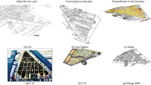

Another important aspect in aircraft structural design is fatigue load analysis. Gao et al. [28, 29] discussed the behavior of composite material in fatigue and how to design structural composite. However, in this paper, we did not include fatigue analysis in the design. Further research and study should be done in the use of composite material in fatigue regime.
2. Research Method
2.1. Problem Statement
The case study is a multi-fighter-type aircraft with a wing planform as shown in Figure 3. Figure 3 is our own design to study the use of anisogrid in fighter wing. The aircraft should be capable to fly with a speed of 500 m/s with a maximum weight of 1400 kg, according to the requirement of the Air Force. For the analysis, the wing was modelled in finite element analysis using MSC Patran. The clamped was placed in the wing root, four of them, that jointed the wing with fuselage, as seen in Figure 3(d). Therefore, this structure belongs to a cantilever type of structure. The ribs, spars, and the lattice structures are seen in Figure 1(a). The wing for the analysis was divided into five parts as seen in Figure 1(b), and the flange model is given in Figure 1(c).
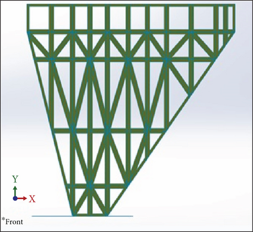
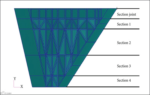
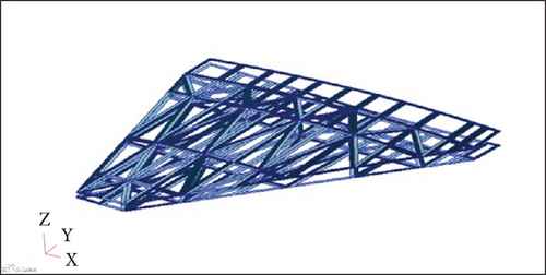
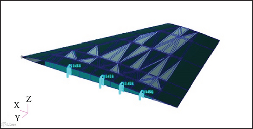
In the finite element analysis, meshing the structure into small element is important. As seen in Figure 3, the wing was made of the skin and the spars and ribs. There are 10 spars and 4 ribs. The numbers of spars and ribs were chosen during the preliminary design of the aircraft, in order to have a good joint between the wing and the fuselage and also to provide joint with flaps and other devices.
During the finite element analysis, the skin is in the form of plate structures, while the frame and the ribs are in the form of beam structures. Therefore, in this analysis, shell element was used to model the skin components, while the beam element was used to model the frame components. Meshing should be done carefully, since finite element results depended mostly on the meshing analysis. In order to ensure the accuracy of the finite element analysis, convergence test was carried out. The result showed that it needed 80,000 elements in the finite element analysis to get a good result with a 20 × 20 cm size shell elements. The convergence result is given in Figure 4.

2.2. Aircraft Loading Analysis
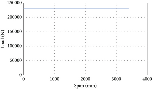
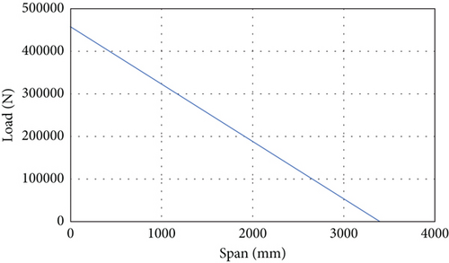
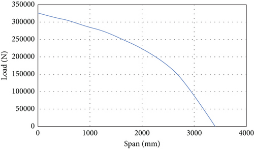
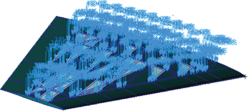
During the analysis, the aerodynamic loads during the flight will be applied to the cantilever wing. Therefore, this is the important factor during the analysis. The loading on the wing structure is conducted with three variations of loading in the spanwise direction: constant distribution, Schrenk distribution, and triangular distribution. The flight condition of the aircraft dictates the magnitude of the applied loading, employing a load factor of N = 9. To ensure safety, a safety factor of 1.5 was applied to the maximum load, as regulated by the international standard, such as US Federal Aviation Administration (FAA) and European Union Aviation Safety Agency (EASA), which was also adopted by Indonesian Directorate of Airworthiness and Aircraft Operation. The load values along the wing span for constant, triangular, and Schrenk loading can be seen in Figures 2(b) and 2(c) and 5(a), while Figure 5(d) shows the actual load loaded on the wing structure during the finite element. The total load of the three types of distribution should be the same or constant.
2.3. Material Data
The material used was carbon fiber–reinforced plastic (CFRP) which is one of the strongest composite material and the mostly used composite materials for aerospace industries. The material properties used are 2D orthotropic materials with the following material properties, as shown in Table 1, and the CFRP density is 1600 kg/m3.
| Modulus of elasticity | ||
|---|---|---|
| E1 | 145,968.29 | MPa |
| E2 | 8407.99 | MPa |
| G12 | 2481.05 | MPa |
| G23 | 2205.38 | MPa |
Table 2 shows the failure strength of this CFRP.
| εT1 (mm/mm) | 0.014143 |
| εT2 (mm/mm) | 0.003324 |
| εC1 (mm/mm) | 0.005889 |
| εC2 (mm/mm) | 0.015802 |
| γ12 (mm/mm) | 0.018602 |
These values will be inputted into MSC Nastran finite element software.
2.4. Composite Modelling
The composite modeling used is a laminated composite, where each ply for the laminate on the composite will be assigned a thickness value and an orientation value. In the model used, the laminate has orientation of [0, +45, −45, 90, 90, −45, +45, 0], or it is called a quasi-isotropic (QI) laminate. Therefore, each sublaminate should have eight layers. The model uses a symmetric stacking sequence so that the thickness of the ply with the same orientation will have the same value. This is done to reduce the number of variables used in the optimization process.
2.5. Aeroelastic Modelling
The wing geometry used to perform aeroelastic and normal mode analysis is simplified by ignoring the leading and trailing edges. The aeroelastic method used for flutter analysis is PK as used in [27]. And the unsteady aerodynamic model used is the doublet-lattice method. The wing structure is said to be safe against static loads if it meets the maximum strain failure criteria.
3. Optimization Modelling
In this paper, optimization is carried out using MSC Nastran SOL 200, which employs a gradient-based optimization algorithm. MSC Nastran’s gradient-based optimization algorithm is a powerful tool that allows for efficient and effective optimization of structures. By utilizing this algorithm, the optimization process can iteratively refine the design to achieve the desired objectives and meet the specified constraints. Leveraging the information provided by the gradients of the objective function and constraints, the gradient-based approach guides the optimization process towards optimal solutions. By driving the optimization process in the direction of steepest improvement, this method ensures improved performance and enhanced design outcomes.
In this study, only the skin, ribs, and spar thicknesses were the subject of optimization. The number of ribs and spars and the distances were not the subject to the optimization process, since the components were attached to a fix position and had other functions, such as attached to fuselages.
3.1. Design Objectives
The optimization process conducted is aimed at obtaining the weight of the wing structure as light as possible, or minimum weight, so that the chosen design objective is weight minimization.
3.2. Design Variables
The design variable used in the optimization process is the thickness of each composite layer of each component of the structure. The initial value of the variable is the initial thickness value of each variable.
3.3. Variable Relationship
Variables for each component with orientations of −45 and +45 are associated with the “general DLINK” feature in the MSC Patran software by defining one of the variables as the dependent variable and one of them as the independent variable. This variable relationship is conducted so that the variables with orientations of −45 and +45 move together so that they produce the same thickness.
3.4. Constraints
The constraints given are based on the type of analysis performed; in this paper, there are three constraints used in the following model.
3.4.1. Static Constraints
3.4.2. Flutter Constraints
3.4.3. Buckling Constraints
4. Results and Discussion
The objective of this study is to develop an anisotropic lattice fighter wing model which has a minimum weight and follows three constraints, namely, static loading, critical buckling loading, and flutter speed of 500 m/s. The results of optimization are given below.
4.1. Optimization Results With Static Strength Criteria
The result of optimizing the thickness of the wing structure with static failure constraints produces a half-wing mass, as shown in Figure 6. Optimization is conducted with three variations of the load distribution in the spanwise direction, namely, the triangular, Schrenk, and constant distributions, as discussed before.
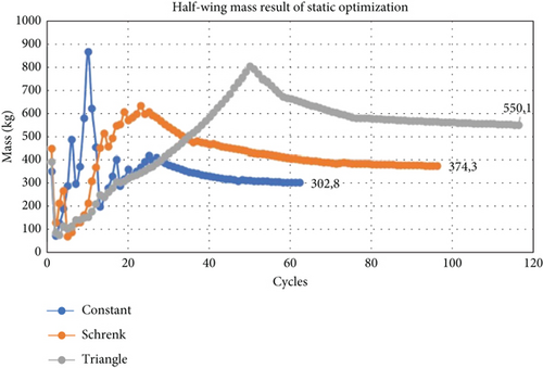
The results in Figure 6 show that the largest mass of the wing structure is the result of optimization with static loading with a constant distribution, and the lowest result is the result of static optimization with triangular distribution loading. The thickness optimization results obtained from MSC Nastran are then rounded up to get the ply number that satisfies the static failure constraint. The results of the number of layers of wing structure can be seen in Table 3. Roman numerals I, II, and II indicate the type of loading with a triangular, Schrenk, or constant distribution.
| Section | Fiber direction | Number of layers | |||||||||||
|---|---|---|---|---|---|---|---|---|---|---|---|---|---|
| Skin | Flange | Rib | Spar | ||||||||||
| I | II | III | I | II | III | I | II | III | I | II | III | ||
| Joint | 0° | 5 | 5 | 8 | 5 | 14 | 37 | 8 | 5 | 3 | 9 | 8 | 80 |
| ± 45° | 3 | 5 | 5 | 12 | 6 | 6 | 58 | 44 | 18 | 4 | 5 | 25 | |
| 90° | 2 | 1 | 2 | 6 | 3 | 2 | 81 | 83 | 10 | 2 | 4 | 2 | |
| Total | 26 | 32 | 40 | 70 | 58 | 102 | 410 | 352 | 98 | 38 | 44 | 264 | |
| 1 | 0° | 13 | 12 | 13 | 12 | 18 | 17 | 2 | 10 | 6 | 7 | 8 | 22 |
| ± 45° | 3 | 5 | 10 | 3 | 6 | 25 | 4 | 11 | 17 | 4 | 2 | 9 | |
| 90° | 2 | 9 | 4 | 8 | 6 | 12 | 20 | 14 | 25 | 2 | 2 | 9 | |
| Total | 42 | 62 | 74 | 52 | 72 | 158 | 60 | 92 | 130 | 34 | 28 | 98 | |
| 2 | 0° | 9 | 14 | 15 | 7 | 11 | 13 | 2 | 2 | 2 | 2 | 2 | 5 |
| ± 45° | 4 | 3 | 3 | 5 | 4 | 6 | 2 | 3 | 10 | 2 | 2 | 3 | |
| 90° | 2 | 4 | 9 | 2 | 13 | 21 | 2 | 2 | 6 | 1 | 2 | 2 | |
| Total | 38 | 48 | 60 | 22 | 64 | 92 | 16 | 20 | 56 | 14 | 16 | 26 | |
| 3 | 0° | 3 | 5 | 4 | 5 | 8 | 6 | 1 | 1 | 2 | 2 | 2 | 2 |
| ± 45° | 2 | 3 | 3 | 2 | 3 | 3 | 2 | 4 | 2 | 2 | 2 | 2 | |
| 90° | 3 | 2 | 8 | 2 | 1 | 5 | 1 | 1 | 2 | 2 | 1 | 2 | |
| Total | 20 | 26 | 36 | 22 | 30 | 34 | 12 | 20 | 16 | 16 | 14 | 16 | |
| 4 | 0° | 2 | 2 | 3 | 2 | 2 | 2 | 2 | 2 | 2 | 2 | 1 | 1 |
The results of the static analysis and the mass of the half-wing optimization with the static failure constraint are shown in Table 4.
| Results | Load distribution | ||
|---|---|---|---|
| Triangular | Schrenk | Constant | |
| Largest displacement (mm) | 318 | 342 | 330 |
| Largest strain (mm/mm) | 0.00383 | 0.00340 | 0.00386 |
| Greatest support force (kN) | 1290 | 1550 | 2280 |
| Failure indices | 0.997 | 0.942 | 0.910 |
| Mass (kg) | 340.4 | 406.8 | 589.5 |
The result of the static analysis in Table 4 shows that the failure indices are below the value of 1, so the design used can be said to be safe against static loads.
4.2. Optimization Results With Buckling Constraints
Figure 7 displays the mass history of the wing structure as an optimization result. The load distribution in the spanwise direction, represented by triangular, Schrenk, and constant distributions, demonstrates the effect of the buckling failure constrain.
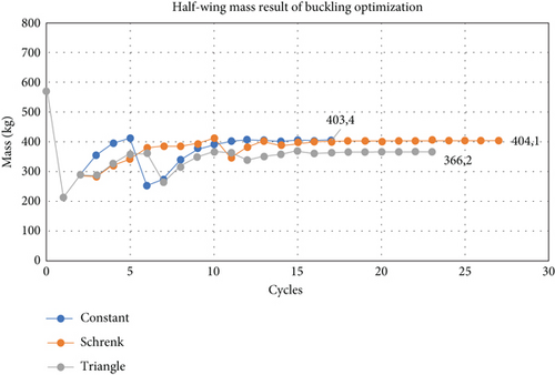
The results in Figure 7 show that the largest mass of the wing structure is the result of optimization with Schrenk loading, and the smallest result is from triangular loading. The result of the buckling analysis for the wing structure after the optimization process with buckling failure constraints can be seen in Table 5. The results in Table 5 show the absolute value of the buckling factor above 1, so the design used can be said to be safe against buckling.
| Span lift distribution | Triangular | Schrenk | Constant | |
|---|---|---|---|---|
| Mass (kg) | 405.6 | 444.3 | 433.0 | |
| Buckling factor | Mode 1 | 1125 | 1205 | 1220 |
| Mode 2 | 1196 | 1335 | 1293 | |
| Mode 3 | 1269 | 1361 | 1365 | |
| Mode 4 | 1291 | 1385 | 1405 | |
| Mode 5 | 1419 | 1410 | 1414 | |
4.3. Optimization Results With Flutter Constraint
The optimization results for the thickness of the wing structure with the flutter speed constraint resulted in a wing structure mass of 80.5 kg, as shown in Figure 8. The results show that the wings can withstand flutter loads well, even with a low thickness.
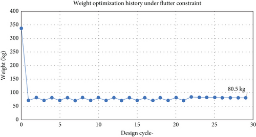
As shown in Figure 8, the minimum weight for the flutter requirement is 80.5 kg. This is the minimum weight in order for the wing to fulfil the flutter constraints. The normal mode analysis is given in Table 6.
| Mode | Frequencies (Hz) | Mode shape |
|---|---|---|
| 1 | 17.04 | 1st bending |
| 2 | 67.61 | 1st torsion |
| 3 | 79.56 | 2nd bending |
The damping versus speed graph and the frequency versus speed graph are given in Figure 9.
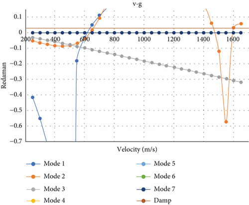
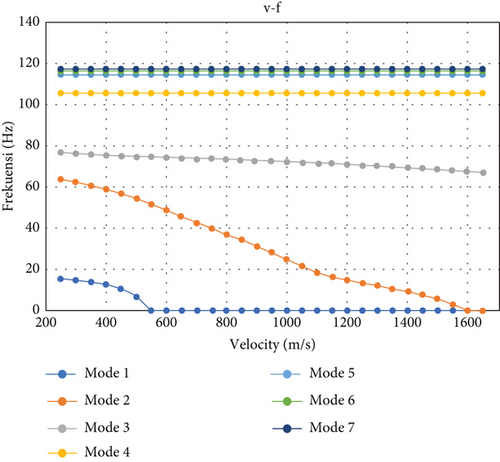
The results as shown in Figure 9 show that there is a divergence at a speed of 635 m/s in the first mode with optimization using the flutter constraint, so it can be said that the design obtained is safe for flutter speeds at speeds below 500 m/s.
4.4. Optimization Results for All Constraints
The result from the optimization process considering all the three constraints, which are static strength, buckling strength, and flutter speed, is summarized in Figure 10.
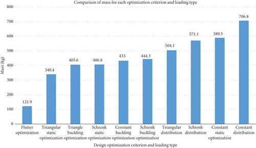
Figure 10 shows that flutter criterion needs the least weight in order to fulfil the criteria. Nevertheless, using the wing flutter design, it will not be enough for the other two criteria: static and buckling. Therefore, the wing flutter design will fail under the static and buckling loads. In order to satisfy the three criteria together, which are flutter, static, and buckling, the wing should be designed with the weight of 707 kg. It should be important to note that in this analysis, static loading is the critical loading to be taken into account, not the buckling and flutter loading. Usually, buckling load is the critical one [27] or even the flutter load. It seems that the anisogrid type of structure increases the bending and torsional stiffness that buckling and flutter are not the critical ones.
It should be noted, however, that the maximum weight was needed for the extreme loading condition, which was constant aerodynamic loading along the wing span. In actual condition, however, the loading should be between Schrenk and triangular distributions. Therefore, the half-wing weight of 504–507 kg should be sufficient for the aircraft wing to perform well without fail.
5. Conclusion
The paper presented here successfully conducted an optimization study of an anisogrid lattice fighter wing structures, using three constraints: flutter speed, static strength, and buckling strength. Finite element modeling was used extensively, using MSC Nastran which is the standard finite element analysis tool for aerospace industries worldwide.
The optimization of the wing structure had been conducted using the static, buckling, and flutter load constraints. The optimization process yielded a design that satisfied the static, buckling, and flutter requirements. In the case of triangular load distribution, it produced the result of a half-wing mass of 504.1 kg. For the distribution of the Schrenk loading, it was obtained that the half-wing mass was 571.1 kg, and for the constant distribution, it was obtained that a half-wing mass was 706.8 kg. The flutter and buckling loads were not the critical design loads anymore. It is the static load which is the critical one. It seems that the anisogrid type of structures increases the bending and torsional stiffness as expected.
Conflicts of Interest
The authors declare no conflicts of interest.
Funding
The authors thank the Faculty of Mechanical and Aerospace Engineering for providing the research fund through P2MI in the year 2021.
Acknowledgments
The authors thank the Faculty of Mechanical and Aerospace Engineering for providing the research fund through P2MI in the year 2021–2022. Bambang Kismono Hadi is the responsible person for the funding.
Open Research
Data Availability Statement
Further data is available upon request.


