Mechanism and Application of Attitude and Orbit Coupling Dynamics for Spacecraft Proximity Relative Motion
Abstract
This paper analyzes the root causes of attitude-orbit coupling effects of spacecraft proximity relative motion in space precision collaborative tasks from three aspects: mathematical representation, physical definition, and engineering applications. At first, taking mathematical representation as the context, spacecraft proximity relative motion representations such as particle relative dynamic model, extended particle relative dynamic model, and dual-spiral-based relative dynamic model are investigated in detail. On this basis, the mechanism of attitude-orbit coupling effects originating from different mathematical representations is further investigated. Second, spiral theory–based attitude-orbit coupling relative dynamics is developed. The innovation of this work is extending the dual number representation from rigid body to flexible body, which makes it possible to describe the proximity relative motion between two rigid-flexible coupling spacecraft. Third, the application value of attitude-orbit coupling relative dynamic model in precision collaborative mission such as precision formation, rendezvous and docking, space manipulation, and on-orbit assembly is provided. Finally, simulation results verify the engineering significance of the attitude-orbit coupling relative dynamic model.
1. Introduction
In the research of spacecraft proximity collaborative tasks, such as rendezvous and docking, precision formation, space manipulation, and on-orbit assembly, many scholars have proposed the necessity of attitude-orbit coupling modeling [1–5]. Some scholars have applied the attitude-orbit coupling results to spacecraft guidance, navigation and control (GNC) [6, 7]. Liu et al. [8, 9] proposed various effective attitude-orbit coupling control methods. Obviously, in the field of spacecraft relative dynamics, navigation, and control, attitude-orbit coupling is not a new issue. However, to the author’s knowledge, there is no research that has clearly defined attitude-orbit coupling. It is specifically a mathematical problem, a physical phenomenon, or an engineering application problem arising only from practical processes, and there is still controversy.
Due to the unsystematic academic investigations on attitude-orbit coupling, the research results have little guiding significance for engineering applications. In terms of engineering practice, most space missions such as rendezvous and docking [10] and space manipulation technology demonstrations [11] have been successfully deployed on orbit and achieved highly accurate spacecraft cooperative operations without considering the impact of attitude-orbit coupling effect. In the above aerospace engineering tasks, Hill-Clohessy-Wiltshire (HCW) equations [12] are the most widely used relative dynamic model. Obviously, it is not an attitude-orbit coupling relative dynamic model.
The viewpoint proposed in Refs. [1–5] conflicts with the engineering application research in Refs. [10–12], which makes scientific aerospace engineers to wonder whether the research work on attitude-orbit coupling relative dynamic model is necessary, or under what circumstances it is necessary. In addition, in ground experiments, the spacecraft simulator’s relative attitude maneuver does not cause relative translational motion [13], which means that the attitude-orbit coupling phenomenon is not explicitly expressed in the physical level, if engineering errors such as inaccurate centroid identification of the spacecraft simulator are ignored.
This paper clarifies, at the first part, the confusion about mechanism and application of attitude-orbit coupling effect and gives a clear definition of attitude-orbit coupling effect. Then, a spiral theory–based attitude-orbit coupling relative dynamic model is developed, which describes the 6-DOF relative motion between spacecraft, whether the spacecraft is a rigid body or a rigid-flexible coupling system, with one equation by using six-dimensional spinor dual vector. Therefore, the spiral theory–based model is known as integrated model [14–16]. Finally, taking spacecraft flying formation as an example, the application value of attitude-orbit coupling relative dynamic model in precision collaborative mission is provided, and simulation results verify the engineering significance of the attitude-orbit coupling relative dynamic model.
2. Mechanism Analysis of Attitude-Orbit Coupling Effects
Aiming at the root cause of the attitude-orbit coupling effects in spacecraft proximity relative motion, taking mathematical representation as the context, the mechanism of attitude-orbit coupling effects originating from different mathematical representation is investigated.
2.1. Particle Model
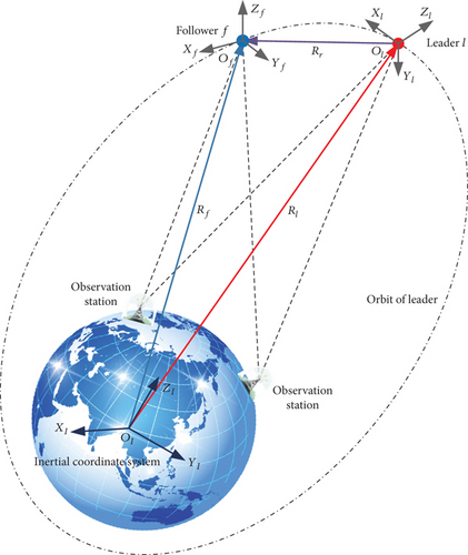
Equation (2) is derived by using quaternion mathematical representation, wherein Jf is the moment of inertia of follower, ωe denotes the angular velocity tracking error, and τf and df denote the control torque and external interference torque acting on the follower. Note that all vectors in Equations (1) and (2) are expressed with respect to the inertial coordinate system. The relative dynamic equation describing the relative 6-DOF motion between spacecraft can be obtained by combining Equations (1) and (2).
Equations (1)–(4) are relative dynamic equations derived from particle model for different engineering applications. Under particle model mathematical framework, the orbital and the attitude motion of spacecraft are independent of each other, and there is no motion projection between the orbital and the attitude motion. Therefore, there is no coupling between the relative attitude and orbit motion between two spacecraft.
2.2. Extended Particle Model
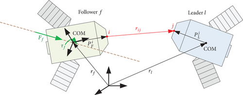
In Equation (6), it can be found that the relative translational motion is affected by the relative angular velocity ωe; that is, the spacecraft proximity relative motion is affected by attitude-orbit coupling. Through the simulation of precision formation and rendezvous and docking, Segal and Gurfil conclude that the larger the size of a rigid spacecraft, the stronger the impact of the attitude-orbit coupling effect on the relative motion.
According to the conclusions of the above research, the attitude-orbit coupling effect originates from the relative dynamics between two noncentroid points. It can be inferred that when the particle and COM coincide, the impact of attitude-orbit coupling on relative motion is zero, which is the same as the conclusion drawn in Section 2.1. Obviously, Equation (5) describes a special scenario, not a general equation.
2.3. Spiral Theory–Based Relative Dynamic Model
Equation (6) describes the relative dynamics between the COMs of the spacecraft. However, the attitude-orbit coupling effect occurs. Obviously, this conclusion conflicts with the research conclusions of Equations (1)–(5). It is worth mentioning that Pan and Kapila did not explain the cause of attitude-orbit coupling in Ref. [26] but focused on studying the impact of spacecraft attitude motion caused by gravity gradient torque on relative orbital motion.
Both Equations (6) and (7) describe the relative motion between the COMs of spacecraft, and the attitude-orbit coupling phenomenon occurs in both equations. Unfortunately, none of the above investigations focused on the mechanism of attitude-orbit coupling phenomenon, but rather on the trajectory offset caused by attitude-orbit coupling effects. It makes engineers wonder what is the root cause of attitude-orbit coupling and what is the difference between the application scenarios of attitude-orbit coupling models and attitude-orbit-independent models.
To clarify this confusion, by analyzing Equations (1)–(4) and Equations (6) and (7), it can be found that Equations (6) and (7) are attitude-orbit coupling relative dynamic model, Equations (1)–(4) are attitude-orbit-independent relative dynamic model, and the above equations all describe the relative motion between COMs of spacecraft. In addition to the mathematical representation, another one of the main differences of above equations is the reference coordinate system. In detail, the reference coordinate system of Equations (1) and (2) is the geocentric inertial coordinate system; the reference coordinate system of Equations (3) and (4) is the orbital coordinate system of leader; the reference coordinate system of Equations (6) and (7) is the body-fixed coordinate system of follower. Based on the above facts, we propose the following conjecture: attitude-orbit coupling effect between the COMs of spacecraft originates from the selection of reference coordinate system.
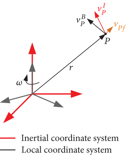
As shown in Figure 3, the position vector of a particle P in the inertial coordinate system is r, the velocity of particle P in the inertial coordinate system is , and the velocity of particle P in the local coordinate system is . The relationship between the two can be described as . Specifically, in the description of relative motion of spacecraft, the motion of the COM of leader relative to the COM of the follower is described using the body-fixed coordinate system of the follower as a reference system, thereby introducing relative rotational motion in relative translational motion, resulting in an attitude-orbit coupling characteristic. Therefore, the following inference can be obtained.
Ratiocination Definition 1. Attitude-orbit coupling is the physical phenomena that occur when describing the relative motion between the COMs of spacecraft with respect to a local coordinate system, namely, body-fixed coordinate system.
Ratiocination Definition 2. The dynamic equation also contains attitude-orbit coupling terms even if describing the 6-DOF motion of a single spacecraft with respect to the body-fixed coordinate system. Further, even if the origin of the body-fixed coordinate system coincides with the COM of this spacecraft, the centroid dynamics is also affected by attitude-orbit coupling effect.
2.4. Summary of the Attitude-Orbit Coupling Problems
- 1.
The point of motion described by the dynamic equation does not coincide with the point of application of the external force, resulting in additional torque, which leads to attitude-orbit coupling of motion of a single spacecraft, and then, this attitude-orbit coupling effect affects the relative motion between two spacecraft, as shown in Equation (5).
- 2.
Attitude-orbit coupling phenomena occur by using the body-fixed coordinate system as a reference coordinate system to describe relative motion between two spacecraft, as shown in Equations (6) and (7).
Source 1 is a special engineering scenario, and Equation (5) is not a general equation. Therefore, there is little investigation on attitude-orbit coupling relative dynamic modeling caused by source 1. In the following sections of this paper, for attitude-orbit coupling caused by source 2, spiral theory–based attitude-orbit coupling relative dynamics is investigated in detail. The innovation of this work is extending the dual number representation from rigid body to flexible body, which makes it possible to describe the proximity relative motion between two rigid-flexible coupling spacecraft.
3. Spiral Theory–Based Attitude-Orbit Coupling Relative Dynamics
Equation (7) is the spiral theory–based relative dynamics between two rigid spacecraft. Based on Equation (7), the relative dynamic model between two rigid-flexible spacecraft is provided. This model can solve the problem of motion description of spacecraft formation with rigid and flexible spacecraft investigated in Ref. [30].
3.1. Definition of the Coordinate Systems and Equation Assumptions
- a.
Earth-centered inertial coordinate system ΨI: the ECI frame is a classic frame for spacecraft dynamic analysis. It has the +z-axis pointing at the north pole, the +x-axis pointing at the vernal equinox, and +y completing the right-hand set.
- b.
Body-fixed coordinate system of leader ΨA: it has the origin locating at the COM of leader, with +z-axis pointing at the working part, +x pointing the relative measuring sensor of leader, and +y completing the right-hand set.
- c.
Body-fixed frame of follower ΨB: it has the origin locating at the COM of follower, with +z-axis pointing at the flexible appendages, +x pointing the relative measuring sensor of follower, and +y completing the right-hand set.
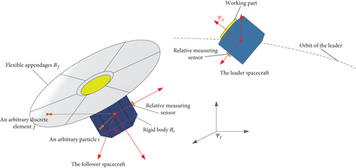
The following notations are employed: denotes the components of x expressed in the body-fixed coordinate system of the follower, and denotes the components of x expressed in the body-fixed coordinate system of the leader.
The derivation of relative dynamics requires the following three conditional assumptions.
Assumption 1. The position of COM and the moment of inertia of the rigid-flexible coupling spacecraft remain unchanged under the vibration of the flexible appendages.
Assumption 2. There is no relative rotation and translation between the flexible appendages and the rigid base; that is, the rigid-flexible spacecraft has a stable configuration.
Assumption 3. The elastic displacement of the flexible appendages is assumed to be small and yields to the linear elasticity theory.
3.2. Attitude-Orbit Coupling Dynamics of the Follower
3.2.1. Dual-Spinor Representation of the Flexible Appendages
3.2.2. Dual-Spinor Representation of the Rigid Base
3.2.3. Dual-Spinor Representation of the Dynamics of Rigid-Flexible Coupling Spacecraft
Note that Equation (33) can be adopted only when the reference coordinate system of the 6-DOF dynamics is a local coordinate system. That is, the dynamics and relative dynamics based on dual number with Newton-Euler form is derived with respect to the body-fixed coordinate system.
3.3. Dual-Spinor Representation of Relative Dynamics Between a Rigid-Flexible Spacecraft and a Rigid Spacecraft
By combining Equations (35), (37), and (38), the relative kinematic and dynamic equations between two flexible spacecraft are obtained. It is worth noting that the dynamic model developed in Equation (27) is applicable to both circular and elliptical orbits.
4. Analysis of Engineering Application Advantages
- 1.
In terms of mathematical expression, the dual-spinor-based attitude-orbit coupling relative dynamic model is an integrated representation, which is more concise in mathematical expression and faster in numerical calculation compared to the particle model.
- 2.
In terms of physical phenomenon presentation, the dual-spinor-based attitude-orbit coupling relative dynamic model illustrates the relative motion phenomenon using oneself as an observer.
- 3.
In terms of engineering application, in spacecraft GNC systems, the measured results of currently developed high-precision measurement sensors of relative states, such as high-accuracy metrology sensor based on laser metrology in PROBA-3 mission [32] and optical sensor in multispacecraft formation mission [33], are the relative differentials with respect to the spacecraft body-fixed coordinate system. Therefore, the controller constructed based on the attitude-orbit coupling model achieves higher control accuracy.
5. Simulation and Results
In this section, the advantage of engineering application of the attitude-orbit coupling relative dynamics is verified by numerical simulation. The GNC system of the spacecraft in a spacecraft proximity mission is shown as Figure 5. Taking the measurement sensors (high-accuracy metrology sensor based on laser metrology) of the PROBA-3 mission as an example, measured results are the relative differentials with respect to the spacecraft body-fixed coordinate system of the follower and have 25 μm measurement accuracy, as shown in Figure 6.


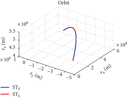
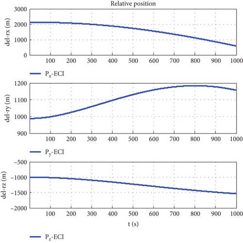
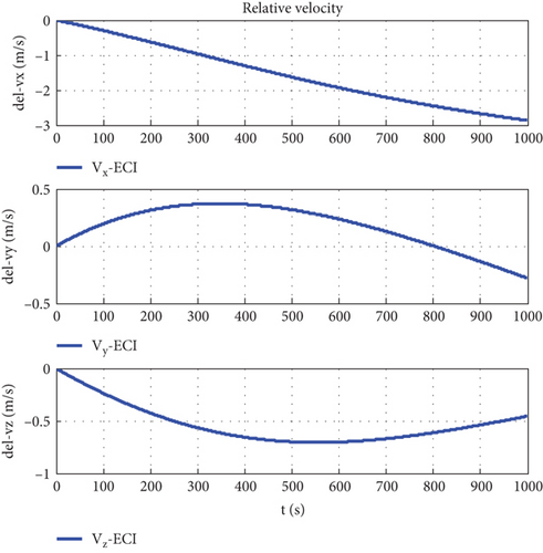
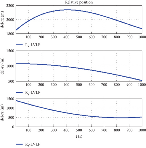
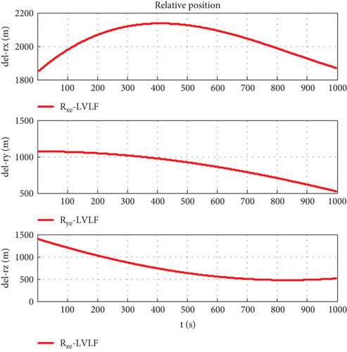
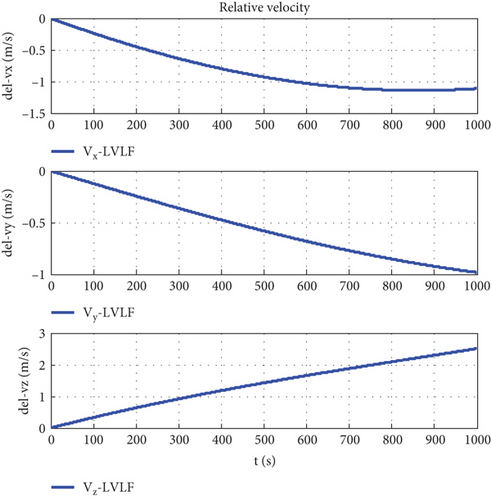
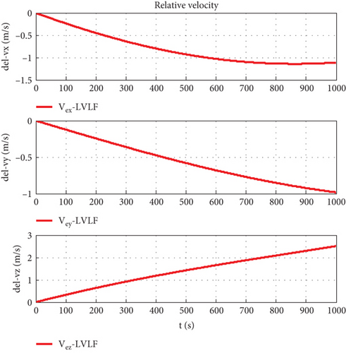
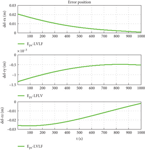
Taking the body-fixed coordinate system of the follower as the conference coordinate system and assuming that the orbit determination accuracy is Δr = 100 m, the simulation step length is 0.1 s, and the simulation time is 1000 s, and using the coordinate conversion matrix CIO, the relative motion states are shown in Figures 7–16.
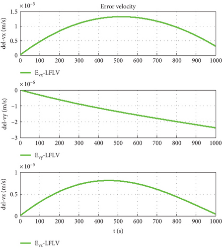
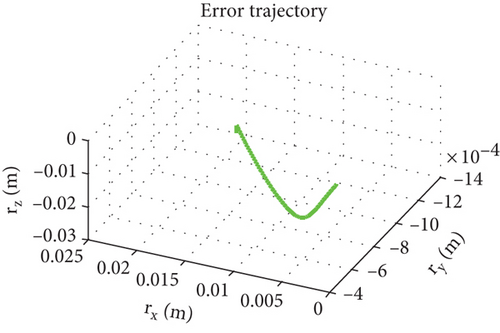
The orbit determination accuracy is set to Δr = 10 m, and other parameters remain unchanged. Simulation results are shown as Figures 17–19.
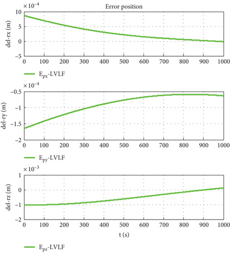
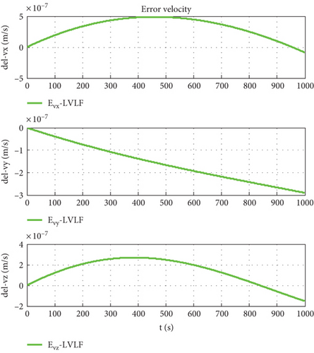
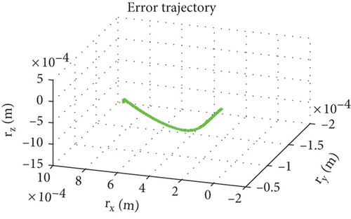
The orbit determination accuracy is set to Δr = 1 m, and other parameters remain unchanged. Simulation results are shown as Figures 20–22.
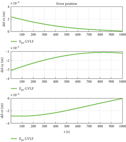
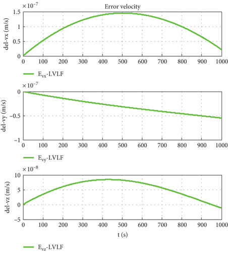
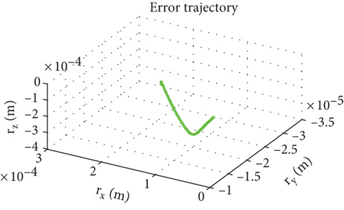
Figure 7 is the relative trajectory of two spacecraft in the inertial coordinate system, where the red line represents the trajectory of the leader and the blue line represents the trajectory of the follower. Figures 8 and 9 show the true values of the relative positions and velocities of two spacecraft in the inertial coordinate system, respectively. Figures 10 and 11 show the three-axis relative position curve between two spacecraft in the body-fixed coordinate system of the follower when orbit determination accuracy is zero and Δr, respectively. Figures 12 and 13 show the three-axis relative velocity curve between two spacecraft in the body-fixed coordinate system of the follower when orbit determination accuracy is zero and Δr, respectively. Figure 14 is the three-axis relative position error between two spacecraft due to coordinate conversion errors with respect to the body-fixed coordinate system of the follower, which is the difference curve between Figures 10 and 11. Figure 15 is the three-axis relative velocity error between two spacecraft due to coordinate conversion errors with respect to the body-fixed coordinate system of the follower, which is the difference curve between Figures 12 and 13. Figure 16 shows the relative motion trajectory error of two spacecraft due to coordinate conversion errors. Figures 17 and 20 is the three-axis relative position error between two spacecraft due to coordinate conversion errors with respect to the body-fixed coordinate system of the follower when Δr = 10 m and Δr = 1 m, respectively. Figures 18 and 21 is the three-axis relative velocity error between two spacecraft due to coordinate conversion errors with respect to the body-fixed coordinate system of the follower when Δr = 10 m and Δr = 1 m, respectively. Figures 19 and 22 show the relative motion trajectory error of two spacecraft due to coordinate conversion errors when Δr = 10 m and Δr = 1 m, respectively.
From Figure 14, we can conclude that when the orbit determination error is 100 m, the relative position description error caused by coordinate conversion errors is about 0.03 m, which indicates that, even if the relative data obtained by spacecraft using relative measurement sensors are absolutely accurate, the error caused by coordinate rotation can reach 0.03 m. This error even exceeds the measurement error of the sensor (25 μm). According to Figures 12, 13, and 15, the relative velocity description error caused by coordinate conversion error is about 0.015 mm/s. From Figures 14, 17, and 20, we found that the higher the orbit determination accuracy, the smaller the error caused by coordinate conversion, but it is still greater than the measurement error of the relative measurement sensor. From Figures 7–16, it can be seen that within 1000 s, the relative motion error between spacecraft caused by coordinate conversion increases as a whole over time. Considering the high efficiency characteristics of precision collaborative tasks such as precision spacecraft formation flying, the one-time working time of the spacecraft will not be too long. Therefore, the simulation duration of 1000 s is within a reasonable range, resulting in a relative motion description error of about centimeters, which basically exceeds the indicator requirements for precision collaborative tasks such as precision spacecraft formation flying.
6. Conclusions
This article mainly completes two innovative contents. First, through the study of attitude-orbit coupling dynamic mechanism and mathematical representation, we conclude that one of the main root causes of attitude-orbit coupling effects of spacecraft proximity relative motion is the selection of the reference coordinate system. Second, through extending the representation of dual spinors to flexible body, the attitude-orbit coupling dynamic model between a rigid-flexible coupling spacecraft and a rigid spacecraft is developed. Based on the above analysis and modeling work, the engineering application advantages of the attitude-orbit coupling relative dynamics is provided. Simulation results show that in GNC systems for precision collaborative missions, the use of attitude-orbit coupling relative dynamic model can reduce the errors and computational complexity caused by coordinate conversion. Our next work is aimed at investigating control methods based on attitude-orbit coupling dynamics, like model predictive control method [34] linear matrix inequality approach [9], and other control method [35–37].
Conflicts of Interest
The authors declare no conflicts of interest.
Funding
This research was supported by the Fundamental Research Funds for the Central Universities of China (No. 3072022JC0202), the project D030307.
Open Research
Data Availability Statement
The data used to support the findings of this study are included within this paper.


