Path Tracking Control of Fixed-Wing Unmanned Aerial Vehicle Based on Modified Supertwisting Algorithm
Abstract
This paper focuses on the issues of low path tracking precision and weak disturbance rejection capability in fixed-wing unmanned aerial vehicle (UAV). This study designs a path tracking controller that combines the radial basis function (RBF) neural network and the supertwisting sliding mode control (STSMC) algorithm. The theoretical stability of the proposed controller is proved by using the Lyapunov theory. The research begins by establishing the motion model of the fixed-wing UAV. The designed controller, integrating the RBF neural network and STSMC, is implemented to enable the UAV to focus on accurately tracking the desired path. The RBF neural network is utilized to estimate and compensate for external disturbances within the model. Validation of the proposed approach is conducted through semiphysical simulation experiments, demonstrating that the designed control method can effectively enhance anti-interference ability and suppress chattering.
1. Introduction
With the rapid advancement of information technology, the level of intelligence continues to rise. In today’s world, fixed-wing unmanned aerial vehicles (UAVs) have garnered significant attention due to their high stability, long endurance, and remote operation capabilities. They are widely used in various fields such as military, agriculture, and exploration [1–5]. The fixed-wing UAV is equipped with advanced low-energy-consumption multiprocessors [6] and camera devices, enabling efficient collection of extensive geographical data. It performs multimodal tasks, utilized in environmental conservation sectors such as meteorological monitoring, natural disaster alerts, and forest fire surveillance [7]. In the agricultural sector, fixed-wing UAVs can fly along predetermined paths, collecting data on soil, vegetation, humidity, and other aspects. This data can be utilized to enhance crop yield and quality while minimizing resource wastage [8]. In the military field, the formation flight of drones [9] flying can effectively reconnaissance terrain, search, and rescue. As flight missions become increasingly complex, there is a growing demand for higher tracking and control performance in fixed-wing UAVs. Given that UAVs often operate at high altitudes and are frequently affected by wind fields, existing fixed-wing UAVs need to possess higher accuracy and robustness to meet these challenges.
In addressing the tracking control problem of UAVs, researchers have proposed many algorithms, such as PID control [10, 11], fuzzy control [12], sliding mode control [13], and ADRC control [14]. Traditional PID control is widely used due to its simplicity. It adjusts based on the UAV’s tracking error, providing good tracking accuracy. Li et al. [15] designed a controller based on quaternion error, combining fractional-order PID control and s-plane to enhance the wind disturbance resistance and tracking accuracy of quadcopter UAVs. Ullah et al. [16] propose integer and fractional adaptive robust schemes for trajectory tracking problem of quad-rotor with cable-suspended payloads. Houm et al. [17] applied nonlinear sliding surfaces to achieve fast convergence of state variables in the control of quadcopter UAVs. An improved supertwisting controller was utilized to suppress disturbances, ensuring robustness against external disturbances. Modern control methods include model predictive control [18] and deep learning [19]. Koo et al. [20] introduced model predictive control to the landing deck process of fixed-wing UAVs. By predicting the motions of the aircraft carrier deck and UAV, it calculates real-time optimal control input sequences within a certain time range, enhancing the UAV’s landing performance. Fang et al. [21] addressed the uncertainty and external disturbance issues of small unmanned helicopters and proposed a robust trajectory tracking controller. Zhang, Li, and Fei [22] combine radial basis function (RBF) neural networks with virtual parameter estimation algorithms to propose a neural network adaptive control scheme for UAVs.
Sliding mode control is fundamentally a special type of nonlinear control that can, during dynamic processes, slide the system state along a sliding surface by switching control laws, ensuring the invariance of the system against external disturbances. Davila, Fridman, and Levant [23] proposed a supertwisting sliding mode control (STSMC) where discontinuous switching functions are incorporated into the integral operation, ensuring the continuity of the control rate over time. This effectively suppresses sliding mode chattering. Matouk et al. [24] designed a control method for quadcopter UAVs based on the supertwisting algorithm, significantly enhancing the stability of the control system. Sami et al. [25] combined the properties of artificial intelligence with STSMC and applied it to the wind energy conversion system (WECS) of doubly fed induction generators (DFIGs), enhancing the anti-interference ability of STSMC. In sliding mode control, the chattering problem [26] is a primary obstacle for the practical application of variable structure control theory. Slotine and Sastry [27] proposed the quasisliding mode approach, introducing the concept of boundary layer and replacing the sign function with a saturation function to effectively mitigate chattering. Mechali et al. [28] presented a fixed-time nonswitching uniform nonsingular terminal sliding mode control method, which is applied to multirotor aircraft. This method effectively suppresses chattering in sliding mode control while addressing singularity issues. In various fields, fixed-wing UAVs often operate in harsh environments and strong wind conditions due to the influence of flight location terrain and climate. Therefore, the control systems of fixed-wing UAVs need to possess strong anti-interference capabilities and control precision, presenting a challenge for existing fixed-wing UAVs.
In this paper, we present the initial integration of the RBF neural networks with the STSMC algorithm into the control system of a fixed-wing UAV. We propose a control methodology that combines the RBF neural networks with the STSMC, leveraging the high robustness of the STSMC and the rapidity and stability of the RBF neural networks to achieve path tracking for fixed-wing UAVs. The main structure of this paper is outlined as follows: The modeling of fixed-wing UAVs is described in the second section. The third section presents the RBF neural network, STSMC, and controller design. The fourth section conducts simulation validation of the proposed controller.
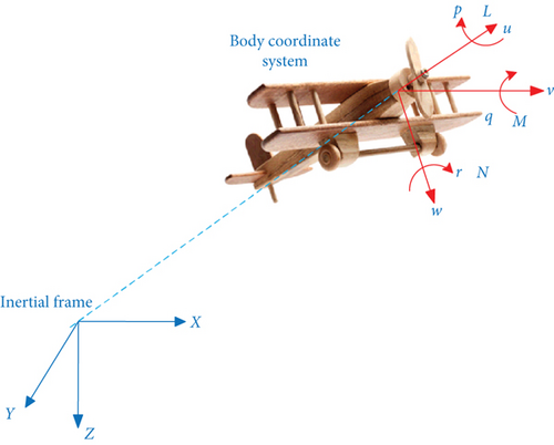
2. Dynamics Model of Fixed-Wing UAV
3. RBF-STSMC Controller
3.1. STSMC
3.2. RBF Neural Network
In the equation, x(t) represents the network input, y(t) represents the network output, cj represents the centroid vector contained in the nodes of the hidden layer, bj represents the width of the Gaussian basis function, m and n are the numbers of nodes in the hidden layer and output nodes, respectively, and W represents the network output weights.
3.3. RBF-STSMC Controller
Assumption 1. , and K = k1/2.
Substituting (25) into (24), we have
Because , the (26) can be rewritten as
When the network approximation error εx becomes sufficiently small, . Therefore, the global stability of the system can be ensured. According to LaSalle’s invariance principle, when L is always equal to zero, s is also always equal to zero.
Similarly, the sliding mode function and the control law for the y direction are given by (28) and (29), respectively:
The structure of the RBF-STSMC controller is shown in Figure 2.

In Figure 1, the position coordinates of points on the expected path and the current position coordinates of the fixed-wing UAV are transmitted to the designed controller and the RBF neural network module. The RBF neural network estimates unknown disturbances and transmits them to the STSMC controller. Based on the error and its rate, the controller calculates the UAV’s speed, pitch angle, and heading angle under the influence of the control rates. These three control inputs are fed into the UAV motion model, obtaining the actual flight path coordinates of the fixed-wing UAV. Part of these coordinates is fed back to the STSMC controller for new control rate calculations, while the other part is transmitted back to the RBF neural network for disturbance estimation. By repeating these processes, the fixed-wing UAV can track the expected path accurately.
4. Simulation and Result Analysis
4.1. Simulation Experiment
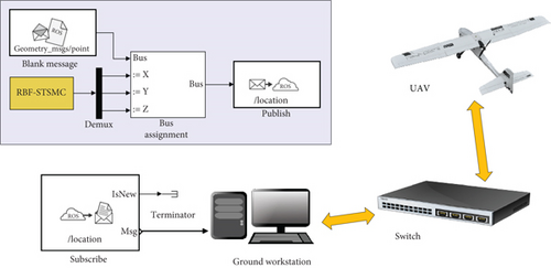
In order to test the control accuracy and anti-interference ability of the RBF-STSMC controller designed in this article, we used the hardware equipment shown in Figure 3 to form a simulation system. This mainly includes ROS simulation systems, ground workstations, switches, and drones. ROS communicates with ground workstations and drones through switches. Its working principle is to use the ROS toolbox to create a node network. Users will configure a module to send “geometry_msgs/Point” messages to the “/location” topic and create a blank ROS message. The RBF-STSMC controller designed in this article will input the tracked position coordinates into the ROS message and then update the ROS message to the ROS network. At this point, the subscription module will subscribe to the messages published in the ROS network, and then, the messages containing the coordinates of the location points will be transmitted to the ground workstation. The ground workstation will send control commands to the drone through the switch to control its flight.
| Parameter | c1 | c2 | c3 | λ1 | λ2 | λ3 | k1 | k2 | k3 |
|---|---|---|---|---|---|---|---|---|---|
| Value | 0.1 | 10 | 0.15 | 10 | 1.0 | 0.5 | 0.5 | 2.0 | 0.2 |
Meanwhile, we used the model equipped with the STSMC controller as a comparison condition. The control parameters for STSMC are set as λi = 0.15 and ki = 0.5. The parameters for the neural network in the RBF-STSMC controller are shown in Table 2.
| Parameter | cij | bj | γi i = 1, 2, 3 |
|---|---|---|---|
| Value | 10 | 50 |
4.2. Result Analysis
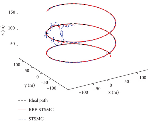
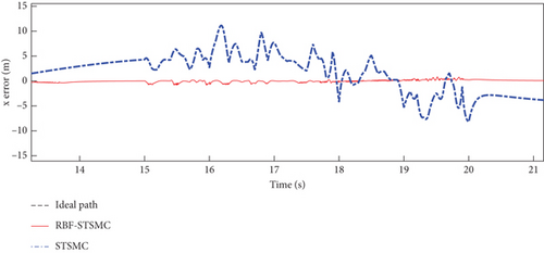
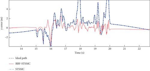
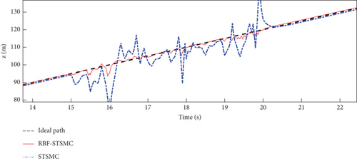
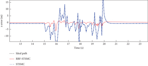
To thoroughly assess the performance of the designed controller in real flight scenarios, white noise was introduced between 15 and 20 s to simulate external disturbances experienced by the fixed-wing UAV. The simulation graph of the fixed-wing UAV flying along the spiral trajectory is shown in Figure 4.
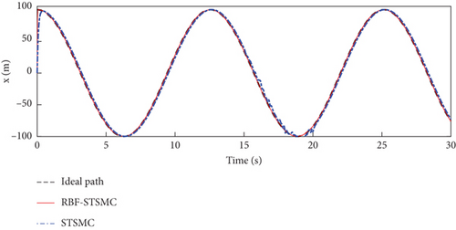
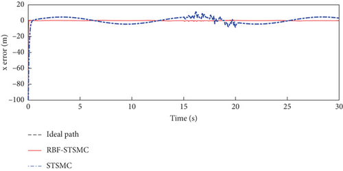
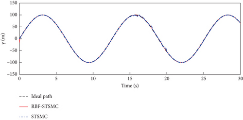
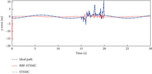
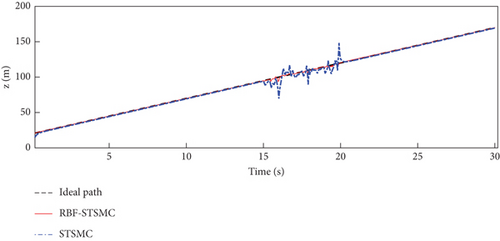
The trajectory tracking performance and errors of the fixed-wing UAV in the x, y, and z directions are shown in Figures 5, 6, and 7.
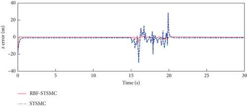
The maximum deviations in the x, y, and z directions are shown in Table 3.
| x direction | y direction | z direction | |
|---|---|---|---|
| STSMC | 11.14 | 10.93 | 28.78 |
| RBF-STSMC | −0.79 | −3.84 | −6.29 |
| IAE | x direction | y direction | z direction |
|---|---|---|---|
| STSMC | 19.35 | 7.26 | 28.75 |
| RBF-STSMC | 5.867 | 7.612 | 8.012 |
| ISE | x direction | y direction | z direction |
|---|---|---|---|
| STSMC | 492.12 | 25 | 262.9 |
| RBF-STSMC | 85.16 | 12.75 | 21.8 |
| ITAE | x direction | y direction | z direction |
|---|---|---|---|
| STSMC | 190.8 | 129.3 | 452.3 |
| RBF-STSMC | 57.86 | 108.5 | 119.1 |
IAE is the integral of the absolute value of error. The JIAE in the x and z directions of RBF-STSMC is smaller than those of STSMC, so the system of RBF-STSMC has a better ability to suppress errors than STSMC.
ISE represents the integral of the squared error, which measures the sum of squared differences between the system output and the expected value. The JISE of RBF-STSMC in all directions is smaller than the JISE of STSMC, indicating that the deviation between the output of RBF-STSMC and the expected value is small, and the system has good stability.
ITAE comprehensively considers the absolute value of error and the integration of time, and to a certain extent, it weighted the duration of error. Therefore, when JITAE is small, the system has a better ability to quickly suppress errors. From the data in the table, it can be seen that the JITAE of RBF-STSMC is smaller than that of STSMC. Therefore, we believe that the RBF-STSMC system has a better ability to quickly suppress errors.
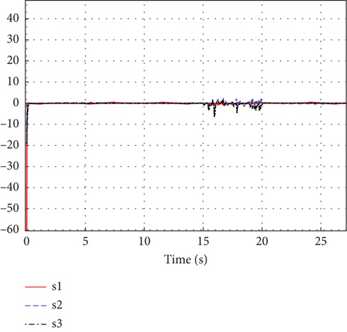
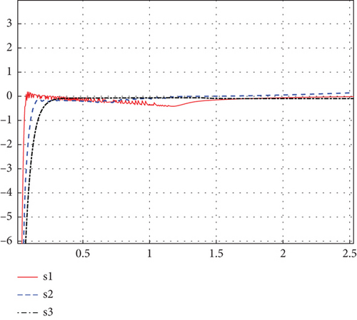
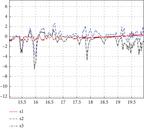
The simulation results of sliding surfaces s1, s2, and s3 are shown in Figures 8 and 9. Figures 9(a) and 9(b), respectively, represent the enlarged schematics of 0–3 s and 15–20 s from Figure 8.
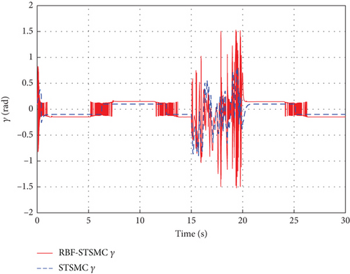
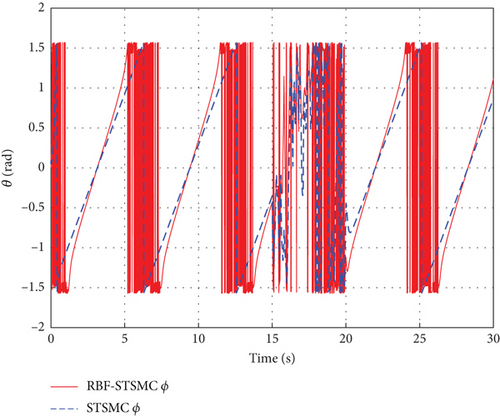
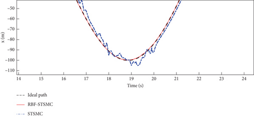
Figures 10 and 11, respectively, illustrate the variation curves of the UAV’s pitch angle and heading angle during the path tracking process. It can be observed that during the disturbance period from 15 to 20 s, although the UAV controlled by RBF-STSMC exhibits rapid angle variations, considering control accuracy, its disturbance rejection capability is stronger. In addition, by zooming in on the curves during the 15–20 s interval with added white noise, as shown in Figures 12, 13, and 14, it can be observed that the controller designed in this study exhibits stronger disturbance rejection capability and tracking accuracy when subjected to external disturbances.

4.3. Discussion
The STSMC can converge in a limited time and has strong robustness. The RBF-STSMC controller designed in this paper combines the advantages of super spiral sliding mode control and the RBF neural network. When the system is affected by external interference, the RBF neural network will estimate and compensate for the interference. As shown in Figure 4, the blue curve in the figure represents the tracking curve of the fixed-wing UAV controlled by the super spiral sliding mode controller, and the red curve represents the tracking curve of the fixed-wing UAV controlled by the RBF-STSMC controller. During the disturbance phase between 15 and 20 s, compared to the STSMC controller, the RBF-STSMC controller has a better suppression effect on interference. From the accuracy diagrams in the x, y, and z directions shown in Figures 5, 6, 7, 8, 9, 10, 11, and 12, it can be seen that the control curve of the RBF-STSMC controller is more stable and the control accuracy is higher.
5. Conclusions
This paper addresses the flight tracking control problem of fixed-wing UAVs in the presence of unknown disturbances. A controller combining the RBF neural network with the STSMC algorithm is proposed. This method reduces the impact of external disturbances on the UAV while mitigating the chattering phenomenon. Furthermore, its performance was verified through comparative experiments. Simulation results indicate that the novel controller, integrating neural networks with STSMC, outperforms the STSMC in terms of tracking accuracy. The results of this work can effectively suppress the external interference problems encountered during the flight of UAVs, which is helpful for the design and development of fixed-wing UAV flight control systems. In the future, we will further improve control algorithms to enhance the accuracy of flight control for fixed-wing UAVs.
Conflicts of Interest
The authors declare no conflicts of interest.
Funding
This work is supported by the National Natural Science Foundation of China (5190924562003314), the Key R&D Plan of Shanxi Province (202202020101001), and the 2023 Project Funding for Technological Initiatives at North University of China (20231975).
Open Research
Data Availability Statement
The data used to support the findings of this study are available from the corresponding author upon request.


