Exploring Solution Strategies for Volterra Integro-Differential Lane–Emden Equations in Astrophysics Using Haar Scale 3 Wavelets
Abstract
The current research introduces a novel approach to address the computational challenges associated with solving the Lane–Emden-type equations by transforming them from their conventional differential form to the corresponding integro-differential form. These equations have wide-ranging applications in physical sciences, including modeling diffusion phenomena and thermal gradients. We utilize the Volterra integro-differential (VID) form to resolve computational challenges due to singularity issues. Through the Scale 3 Haar Wavelet (S3-HW) algorithm, we transform the VID equations into algebraic form and obtain solutions using the Gauss-elimination method. The quasilinearization technique is implemented whenever a nonlinearity is encountered. Comparative analysis against various techniques demonstrates the superior accuracy and efficiency of our method. Despite challenges such as the discontinuity of Scale 3 Haar Wavelets and singularity issues of Lane–Emden-type equations, our algorithm paves the way for extending its application to a wide range of physical problems.
1. Introduction
The study of stellar structures has become a major subject in stellar astrophysics since its origin [1]. The number of attempts have been made to estimate the radial profiles of the density of the star, mass of the star, and also the pressure of the star, and the major finding of all these attempts is the Lane–Emden equation (LE-E). LE-E represents the thermal gradient of a spherical cloud of gas based on laws of basic thermodynamics as well as the mutual attraction among its particles. The polytrophic theory of stars is based on thermodynamic considerations that address the problem of energy transmission via material transfer among multiple levels of the star. These mathematical equations are fundamental to the theory of stellar structure and have also become the subject of numerous research [2, 3]. Mathematically, LE-E is an ordinary differential equation of the second order having singularity at the origin. To derive the basic model of the Lane–Emden equation, consider a spherical gas cloud as presented in Figure 1 [4, 5].
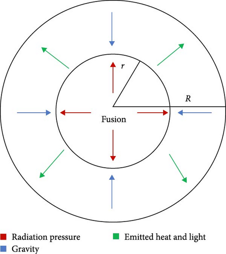
This equation has been used to explain various problems in physical sciences and cosmology, including stellar model theory, isothermal gas sphere, physical properties of a spherical cloud of gas, modeling of the cluster of galaxies, and thermionic current theory [8]. Some of the important real-world applications of the Lane–Emden equation are discussed in Table 1. Lane [13] was the first one to develop Lane–Emden equations, although Emden elaborated extensively in 1870. The Lane–Emden equation is a Poisson equation in astrophysics. This type of problem has received an enormous amount of attention from researchers. For further study on Lane–Emden equations, comprising their origin, modifications, and implementations, the researcher is gladly encouraged to read [1, 12, 13].
Function type f(ϰ, ζ(ϰ)) |
Physical applications |
|---|---|
| ζm(ϰ) | This is the standard LE-E. The exact solution for this LE-E is available in the literature corresponding to m = 0, 1, and 5 only and the solutions are , respectively. This equation describes the thermal gradient of a spherical cloud of gas based on laws of basic thermodynamics as well as the mutual attraction among its particles [9] |
| eζ(ϰ) | This LE-E is the Poisson Boltzmann equation utilized to describe isothermal gas spheres [2, 10] |
| This Lane–Emden equation arises in modeling of the thermal conduction in the human head [11] | |
| This Lane–Emden equation is called the white-dwarf (W-D) equation. This equation finds its application in the modeling of the gravitational potential of degenerate W-D stars [1] | |
| The study of steady-state gas diffusion in a spherical cell with Michaelis–Menten uptake kinetics leads to the development of this equation [12] |
The LE-E generally does not have solutions that can be determined by analytical techniques. In practice, several real physical and mathematical problems are often very difficult to deal with. As a result, these problems are handled by using a variety of approximated and numerical techniques. Several researchers are working on the solution of LE-E. Parand and Hashemi [4] Dehghan and Shakeri [5] solved the LE-E using the variational iteration scheme. Wazwaz [14] solved the Lane–Emden type equations by using the Adomain decomposition method. Caglar and Caglar [15] implemented the B-splines for the approximation of the singular differential equation of the LE-E type. Yousefi [16] described the Legendre wavelets for finding the solution of the Lane–Emden equation. Ertürk [17] solved the Lane–Emden equations in differential form by utilizing the differential transform method. Ramos [18] approximated LE-E by utilizing a series approach. The author also discusses the comparability of the homotopy perturbation method with the series approach for solving Lane–Emden equations. Parand et al. [19] used a pseudospectral algorithm for the solution of Lane–Emden equations having nonlinearity in them on the semi-infinite domain. Vanani and Aminataei [20] presented a numerical method for LE-E of the nonlinear kind. Parand et al. [21] approximated the Lane–Emden equations by utilizing the hybrid collocation approach along with the Hermite function. Iqbal and Javed [22] applied the optimal homotopy asymptotic algorithm on Lane–Emden equations. Wazwaz et al. [23] used the Adomain decomposition method for solving the system of Lane–Emden equations by converting them into the corresponding Volterra integral equations. Taghavi and Pearce [24] applied the Tau technique for the approximation of Lane–Emden equations of differential form. Yüzbaşı and Sezer [25] constructed the Bessel collocation approach for the solution of Lane–Emden equations. Wazwaz and Khuri [26] solved the integrodifferential form of Lane–Emden equations with the aid of the variational iteration method. Asadpour et al. [27] solved the integral form of Lane–Emden equations by using the least square method. Parand and Hashemi [4] and Dehghan and Shakeri [5] employed a novel numerical approach to examine widely recognized categories of Lane–Emden type equations, which are nonlinear ordinary differential equations defined on the semi-infinite domain. The author employs the radial basis function differential quadrature (RBF-DQ) method, a meshless technique. Each technique has its own advantages and limitations, which makes it important to explore and develop new methods to improve the accuracy, efficiency, and robustness of the numerical solutions. Wavelet methods offer several advantages over other numerical methods when it comes to solving integral and integro-differential equations.
Wavelets are modernistic orthonormal functions with the ability to dilate and translate. These characteristics allow wavelet-based numerical algorithms to exhibit a qualitative improvement over other techniques. In literature, Lane–Emden equations have been solved by using numerous wavelets like, Legendre multiwavelets [28], Bernoulli wavelet [29], Chebyshev wavelet [30], Haar scale 2 wavelets [31], Morlet wavelet [32], and Taylor wavelet [33]. Among all wavelet families with analytic expression, the Haar wavelet is the simplest. Haar wavelet technique has superseded the other numerical techniques because of its mathematical simplicity, high levels of efficiency, and primarily its applicability to the problems to acquire more reliable results for a small number of nodal points. The Haar wavelet has been utilized in the literature to address a variety of equations, including the Burgers’ equation [34] and hyperbolic type wave equations [35]. In literature, the most commonly used wavelets are dyadic wavelets. These wavelets have a dilation factor that increases in powers of 2, creating two daughter wavelets. However, Chui and Lian [36] introduced a new class of wavelets called nondyadic (Scale 3 Haar) wavelets through a multiresolution analysis process. More recently, Mittal and Pandit [37, 38, 39] applied scale 3 Haar wavelets to solve various types of differential equations and observed that the scale 3 Haar wavelets exhibit a faster rate of convergence as compared to the dyadic wavelets. Despite this advancement, the scale 3 Haar wavelet-based technique has not been tested on any scientific models governed by integro-differential equations. Moreover, specifically, the scale 3 Haar wavelet method has not been used to investigate the characteristics of solutions to the integro-differential form of the Lane–Emden equation. This knowledge gap motivates us to develop a new technique utilizing scale 3 Haar wavelets for the analysis of system behavior governed by the integro-differential form of Lane–Emden equation.
The current manuscript involves the development and implementation of scale 3 Haar wavelets along with collocation method [40, 41, 42, 43, 44, 45, 46, 47, 48, 49] to solve the Lane–Emden equations in integro-differential form. The paper is organized as follows: in Section 2, a brief study about the Quasilinearization technique is included. The basic structure of scale 3 Haar wavelets and the structure for calculating the integrals of scale 3 Haar wavelets is discussed in Section 3. Section 4 contains the scale 3 Haar wavelet (S3-HW) collocation algorithm. The convergence analysis is provided in Section 5 of the manuscript. For the validation of the S3-HW algorithm, some applications of Lane–Emden equations are discussed in Section 6. Finally, the conclusion is discussed in Section 7 of the article.
2. The Quasilinearization Approach
3. Scale 3 Haar Wavelets
The wavelet family is an orthonormal subfamily of l2(R). From a fixed function known as the mother wavelet, all other functions in the wavelet family are constructed via translations and dilations. In Haar scaling 2 wavelets, a single mother wavelet provides the entire wavelet family, meanwhile, in Haar scale 3, two mother wavelets construct the extended wavelet family. The structure of the wavelet family for the Haar scale 3 along with their integrals is presented in this section [36, 44].
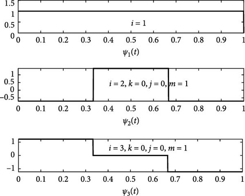
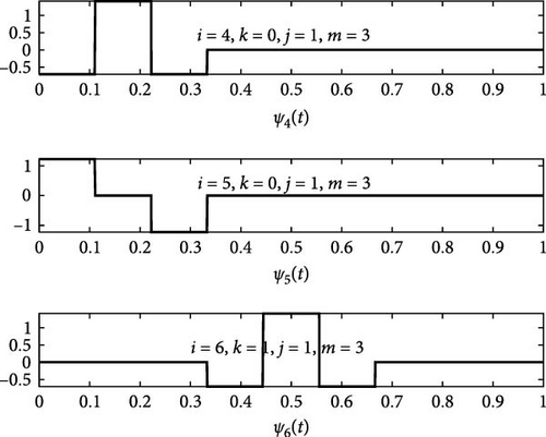
For this wavelet family, the wavelet number is represented by i, the dilation factor is represented by j, and the translation parameter is represented by k. For the computation of wavelet number i following relations are used. i − 1 = 3j + 2k (for even values of wavelet number) and i − 2 = 3j + 2k (for odd values of wavelet number). The whole wavelet family would be constructed by utilizing the abovementioned expressions for various translations and dilations of ψ2(ϰ) and ψ3(ϰ). ψ2(ϰ) and ψ3(ϰ) are considered mother wavelets, and the remaining wavelets formed from these two parent wavelets are referred to as daughter wavelets. The graphs for the first six members of the wavelet family are shown in Figure 2. The primary distinction between the Haar scale 2 and Haar scale 3 wavelets is that the Haar scale 2 uses a single mother wavelet to generate all subsequent wavelets, whereas the Haar scale 3 uses two mother wavelets with different factors as well as different shapes to produce the wavelet family. As a result of this advantage, the Haar scale 3 wavelet accelerates the rate at which solutions converge.
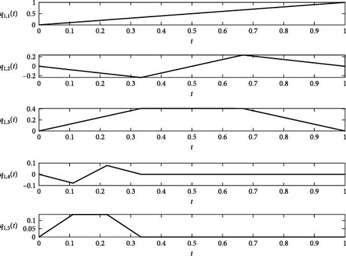
The graphs for the first integrals of the first five members of scale 3 Haar Wavelets are shown in Figure 3.
4. Construction of Scale 3 Haar Wavelet Algorithm
In this section, a novel algorithm is presented for the solution of Lane–Emden equations of VID form. We constructed a scale 3 Haar wavelet algorithm for the interval [0, 1]. In the proposed algorithm, the first-order derivative υ′(ϰ) involved in the Lane–Emden equation is approximated by scale 3 Haar functions, and then by integrating, the value of unknown υ(ϰ) is obtained. Furthermore, the integrals involved are determined by using the formula given in Lemma 1.
Lemma 1. If υ(ϰ) is any function belonging to the family of l2(R), the space of square-integrable function over the interval (a, b) in such a way that , then the integral of υ(ϰ) on (a, b) is given as follows:
Proof. See Kumar and Bakhtawar’s [45] study.
4.1. Proposed Methodology
Any iterative method could be utilized to determine the solution to these equations. For the solution of this linear system, the Gauss elimination method has been implemented. For the nonlinear equations, quasilinearization is used. By solving these algebraic equations, the unknown Haar coefficient has been obtained. Finally, by substituting these Haar coefficients in Equation (38) solution at collocation points has been obtained.
5. Convergence Analysis
Now the convergence of the theorem will be proved with the help of Lemma 2.
Lemma 2. Let υ(ϰ)ɛL2(R)be any square-integrable function such that |υm(ϰ)| ≤ M, ∀ϰɛ(0, 1) and . Then, .
Proof. Let be the exact solution and be the approximated solution. Now the error at the Jth level of resolution is given by the following equation:
Theorem 1. If υ(ϰ) represents the exact solution and υ3p(ϰ) represents the non-Dyadic wavelet-based approximated solution, then:
Proof. At jth level of resolution, error estimation for the solution is given by the following equations:
It is clear from the above equations that error bound is inversely proportional to the level of resolution which means that with the increase in the level of resolution, error bound decreases, i.e., j → ∞⇒‖Ej‖⟶0. This proves the convergence of solution and ensures the stability of the solutions.
6. Numerical Examples
Example 1. Consider the second-order linear Lane–Emden differential equation of the form [14]:
The exact solution for Example 1 is ζ(ϰ) = ϰ2 + ϰ3, and the approximated solution by using the presented algorithm is
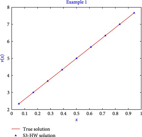
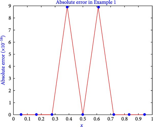
The computation of the true solution and S3-HW solution of Example 1 are given in Table 2 for the level of resolution 1. The results shown in the table demonstrate that the method generates accurate solutions in terms of absolute error (AE) having an error of 10−16. In Table 3, the computation of l2 − error, lmax − error, and l∞ − error is presented. Table 3 illustrates that by increasing the value of j, the error becomes lesser. The comparison of S3-HW errors with that of the Adomain decomposition method and Chebyshev wavelet is given in Table 4, which clearly depicts that our results are better than the previous one. Furthermore, the suggested algorithm has been shown to produce high-accuracy outcomes even with a small number of grid points. Figure 4 also shows the S3-HW solution and true solutions for the level of resolution j = 1. The figure shows that the resulting S3-HW solution coincides well with the true solution. Figure 5 shows the graph of absolute error for Example 1 when j = 1. Moreover, the presented algorithm took only 0.24 s of CPU time to execute the program written for this example.
| ϰ | True solution | S3-HW solution | AE |
|---|---|---|---|
| 0.055555555556 | 2.333333333333 | 2.333333333333 | 0 |
| 0.166666666667 | 3.000000000000 | 3.000000000000 | 0 |
| 0.277777777778 | 3.666666666667 | 3.666666666667 | 0 |
| 0.388888888889 | 4.333333333333 | 4.333333333333 | 8.88178E − 16 |
| 0.500000000000 | 5.000000000000 | 5.000000000000 | 0 |
| 0.611111111111 | 5.666666666667 | 5.666666666667 | 8.88175E − 16 |
| 0.722222222222 | 6.333333333333 | 6.333333333333 | 0 |
| 0.833333333333 | 7.000000000000 | 7.000000000000 | 0 |
| 0.944444444444 | 7.666666666667 | 7.666666666667 | 0 |
| j | l2 − error | lmax − error | l∞ − error |
|---|---|---|---|
| 0 | 0.00000E + 00 | 0.00000E + 00 | 0.00000E + 00 |
| 1 | 7.91776E − 17 | 1.25607E − 15 | 8.88178E − 16 |
| 2 | 0.00000E + 00 | 0.00000E + 00 | 0.00000E + 00 |
| 3 | 9.32507E − 17 | 4.44089E − 15 | 8.88178E − 16 |
| 4 | 8.63088E − 17 | 7.11929E − 15 | 1.77636E − 15 |
| 5 | 8.27657E − 17 | 1.18248E − 14 | 1.77636E − 15 |
| 6 | 1.07181E − 16 | 2.65229E − 14 | 1.77636E − 15 |
Example 2. Next, we have solved the nonlinear Lane–Emden differential equation of the form [46]:
The exact solution for Example 2 is , and the approximated solution by using the presented algorithm is
We have compared the value of absolute error for Example 2 obtained by using the S3-HW algorithm with that of Verma and Tiwari [46] in Table 5. This clearly depicts that the S3-HW algorithm is providing better results. Table 6 demonstrates the order of convergence of presented algorithm using an error table.
| ϰ | Absolute error for HWQA [46] | Absolute error for S3-HW |
|---|---|---|
| 0.2 | 2.90983E − 05 | 5.4250E − 10 |
| 0.3 | 2.33723E − 05 | 2.4290E − 09 |
| 0.4 | 1.72621E − 05 | 6.5520E − 09 |
| 0.6 | 1.16388E − 05 | 2.2080E − 08 |
| 0.7 | 6.90631E − 06 | 3.2627E − 08 |
| 0.8 | 3.12139E − 06 | 4.3902E − 08 |
| 0.9 | 1.62325E − 07 | 5.5151E − 08 |
| Δx | 0.333333 | 0.111111 | 0.037037 | 0.012346 | 0.0041152 | 0.0013717 | 0.0004572 |
| j | 0 | 1 | 2 | 3 | 4 | 5 | 6 |
| l2 − error | 2.45E − 03 | 2.23E − 04 | 2.44E − 05 | 2.71E − 06 | 3.01E − 07 | 3.34E − 08 | 3.71E − 09 |
| Order of convergence | — | 2.18E + 00 | 2.01E + 00 | 2.00E + 00 | 2.00E + 00 | 2.00E + 00 | 2.00E + 00 |
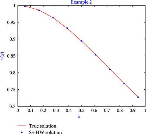
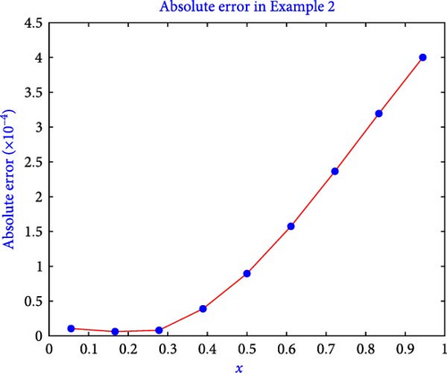
This equation originates in the analysis of isothermal gas sphere equilibrium. The computation of the true solution and S3-HW solution is given in Table 7 for Example 2. The results shown in the table demonstrate that the method generates accurate solutions in terms of absolute error. In Table 8, computation of l2 − error, lmax − error, and l∞ − error is presented. Table 8 illustrates that by increasing the value of j, the error becomes lesser. Figure 6 shows the S3-HW solution and true solutions for the level of resolution j = 1. The figure shows that the resulting S3-HW solution coincides well with the true solution. Figure 7 shows the graph of absolute error for Example 2 when j = 1. Furthermore, the presented algorithm executed the program for this example in just 0.228 s of CPU time.
| ϰ | True solution | S3-HW solution | AE |
|---|---|---|---|
| 0.055555555556 | 0.998460353205 | 0.998470899829 | 1.05466E − 05 |
| 0.166666666667 | 0.986393923832 | 0.986400125001 | 6.20117E − 06 |
| 0.277777777778 | 0.963517909630 | 0.963509847025 | 8.06260E − 06 |
| 0.388888888889 | 0.932004671541 | 0.931965702446 | 3.89691E − 05 |
| 0.500000000000 | 0.894427191000 | 0.894337637786 | 8.95532E − 05 |
| 0.611111111111 | 0.853281833652 | 0.853124378302 | 1.57455E − 04 |
| 0.722222222222 | 0.810679228400 | 0.810442731760 | 2.36497E − 04 |
| 0.833333333333 | 0.768221279597 | 0.767901826959 | 3.19453E − 04 |
| 0.944444444444 | 0.727013152550 | 0.726612960465 | 4.00192E − 04 |
| j | l2 − error | lmax − error | l∞ − error |
|---|---|---|---|
| 0 | 2.45168E − 03 | 3.76885E − 03 | 3.51118E − 03 |
| 1 | 2.23333E − 04 | 5.93868E − 04 | 4.00192E − 04 |
| 2 | 2.44184E − 05 | 1.12448E − 04 | 4.66187E − 05 |
| 3 | 2.70847E − 06 | 2.16029E − 05 | 5.27484E − 06 |
| 4 | 3.00884E − 07 | 4.15668E − 06 | 5.89792E − 07 |
| 5 | 3.34308E − 08 | 7.99937E − 07 | 6.56716E − 08 |
| 6 | 3.71453E − 09 | 1.53948E − 07 | 7.30203E − 09 |
The exact solution for Example 3 is .
The computation of the true solution and S3-HW solution is given in Table 9 for Example 3. In Table 10, computation of l2 − error, lmax − error, and l∞ − error is presented. Table 11 illustrates that by increasing the value of j, the error becomes lesser. The error obtained for Example 3 in [15] is 10−6, in [27] the error is 10−8, and by using the presented algorithm the error obtained is 10−9 at the level of resolution 6, as shown in Table 11. Table 12 demonstrates the order of convergence of presented algorithm using error table.
| ϰ | True solution | S3-HW solution | AE |
|---|---|---|---|
| 0.055555555556 | 0.500579076014 | 0.500386025849 | 1.93050E − 04 |
| 0.166666666667 | 0.505238621326 | 0.505042573279 | 1.96048E − 04 |
| 0.277777777778 | 0.514703340426 | 0.514501165202 | 2.02175E − 04 |
| 0.388888888889 | 0.529274148817 | 0.529062443064 | 2.11706E − 04 |
| 0.500000000000 | 0.549427679501 | 0.549202599104 | 2.25080E − 04 |
| 0.611111111111 | 0.575849911585 | 0.575606964558 | 2.42947E − 04 |
| 0.722222222222 | 0.609487186781 | 0.609220963206 | 2.66224E − 04 |
| 0.833333333333 | 0.651621391086 | 0.651325197151 | 2.96194E − 04 |
| 0.944444444444 | 0.703980101848 | 0.703645447854 | 3.34654E − 04 |
| j | l2 − error | lmax − error | l∞ − error |
|---|---|---|---|
| 0 | 3.77842E − 03 | 3.74378E − 03 | 2.63404E − 03 |
| 1 | 4.26631E − 04 | 7.35990E − 04 | 3.34654E − 04 |
| 2 | 4.74912E − 05 | 1.41987E − 04 | 3.89216E − 05 |
| 3 | 5.27789E − 06 | 2.73329E − 05 | 4.39131E − 06 |
| 4 | 5.86446E − 07 | 5.26038E − 06 | 4.90422E − 07 |
| 5 | 6.51608E − 08 | 1.01236E − 06 | 5.45843E − 08 |
| 6 | 7.24009E − 09 | 1.94830E − 07 | 6.06836E − 09 |
| ϰ | Absolute error in [15] for | Absolute error in [15] for | Absolute error in [25] | Absolute error obtained by using HS 3-W |
|---|---|---|---|---|
| 0.025 | — | 6.0E − 06 | — | 3.26E − 09 |
| 0.050 | 2.0E − 05 | 6.0E − 06 | — | 3.27E − 09 |
| 0.075 | — | 6.0E − 06 | — | 3.27E − 09 |
| 0.100 | 2.7E − 05 | 6.0E − 06 | — | 3.28E − 09 |
| 0.200 | 2.6E − 05 | 6.0E − 06 | 1.5665E − 06 | 3.34E − 09 |
| 0.300 | 2.5E − 05 | 5.0E − 06 | — | 3.45E − 09 |
| 0.400 | 2.4E − 05 | 4.0E − 06 | 1.5577E − 06 | 3.60E − 09 |
| 0.500 | 2.2E − 05 | 3.0E − 06 | — | 3.81E − 09 |
| 0.600 | 1.9E − 05 | 2.0E − 06 | 1.5524E − 06 | 4.08E − 09 |
| 0.700 | 1.5E − 05 | 2.0E − 06 | — | 4.42E − 09 |
| 0.800 | 1.1E − 05 | 1.0E − 06 | 1.551E − 06 | 4.85E − 09 |
| 0.900 | 6.0E − 05 | 1.0E − 06 | — | 5.39E − 09 |
| 1 | 0 | 0 | 1.6198E − 16 | — |
| Δx | 0.33333 | 0.111111 | 0.037037 | 0.012346 | 0.004115 | 0.001372 | 0.000457 |
| j | 0 | 1 | 2 | 3 | 4 | 5 | 6 |
| l2 − error | 3.78E − 03 | 4.27E − 04 | 4.75E − 05 | 5.28E − 06 | 5.86E − 07 | 6.52E − 08 | 7.24E − 09 |
| Order of convergence | — | 1.99E + 00 | 2.00E + 00 | 2.00E + 00 | 2.00E + 00 | 2.00E + 00 | 2.00E + 00 |
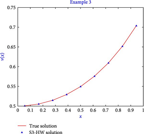
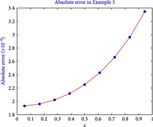
Figure 8 shows the S3-HW solution and true solutions for the level of resolution j = 1. The figure shows that the resulting S3-HW solution coincides well with the true solution. Figure 9 shows the graph of absolute error for Example 3 when j = 1. Moreover, the presented algorithm successfully executed the program for the second example in a mere 0.213 s of CPU time.
Example 4. Last, consider the following Lane–Emden equation. This equation finds its application in stellar structure. The equation is basically originating in the differential form as follows [47]:
The computation of true solution and S3-HW solution for Example 4 corresponding to m = 5 is given in Table 13. In Table 14, computation of l2 − error and l∞ − error is presented. We have also compared the values l2 − error and l∞ − error with that of the method presented in [48]. The value of l∞ − error and l2 − error for j = 6 in [48] is 8.92E−06 and 7.28E−06, while in the presented S3-HW algorithm, the errors are 1.16153E−08 and 2.93359E−08, respectively, which shows that the presented algorithm provides much better results. Table 14 illustrates that by increasing the value of j, error becomes lesser. In Table 15, we have compared the absolute error for the level of resolution six obtained by using the presented method with that of existing results, and this can be observed that the presented method works more efficiently. Table 16 demonstrates the order of convergence of presented algorithm using an error table.
| ϰ | True solution | S3-HW solution | AE |
|---|---|---|---|
| 0.055555555556 | −0.331793425541 | −0.332479068763 | 6.85643E − 04 |
| 0.166666666667 | −0.319708364572 | −0.320345947060 | 6.37582E − 04 |
| 0.277777777778 | −0.296736635324 | −0.297284503406 | 5.47868E − 04 |
| 0.388888888889 | −0.265048420258 | −0.265476353156 | 4.27933E − 04 |
| 0.500000000000 | −0.227400928481 | −0.227692828367 | 2.91900E − 04 |
| 0.611111111111 | −0.186702699731 | −0.186856672356 | 1.53973E − 04 |
| 0.722222222222 | −0.145630818194 | −0.145657044820 | 2.62266E − 05 |
| 0.833333333333 | −0.106368557497 | −0.106285801027 | 8.27565E − 05 |
| 0.944444444444 | −0.070483367951 | −0.070315068968 | 1.68299E − 04 |
| j | l2 − error | l2 − error [48] | l∞ − error | l∞ − error |
|---|---|---|---|---|
| 0 | 1.66492E − 02 | — | 6.14990E − 03 | — |
| 1 | 1.74408E − 03 | — | 6.85643E − 04 | — |
| 2 | 1.92617E − 04 | 4.71E − 04 | 7.62052E − 05 | 1.97E − 03 |
| 3 | 2.13876E − 05 | 1.65E − 04 | 8.46751E − 06 | 4.91E − 04 |
| 4 | 2.37623E − 06 | 5.84E − 05 | 9.40838E − 07 | 1.23E − 04 |
| 5 | 2.64023E − 07 | 2.06E − 05 | 1.04538E − 07 | 3.12E − 05 |
| 6 | 2.93359E − 08 | 7.28E − 06 | 1.16153E − 08 | 8.92E − 06 |
| ϰ | Error in [33] | Error in [40] | Error in [41] | Error obtained by using presented method |
|---|---|---|---|---|
| 0.1 | 6.46E − 06 | 6.27E − 03 | 3.10E − 03 | 1.1282E − 08 |
| 0.2 | 6.30E − 06 | 6.12E − 03 | 2.90E − 03 | 1.0327E − 08 |
| 0.3 | 6.05E − 06 | 5.87E − 03 | 2.60E − 03 | 8.8434E − 09 |
| 0.4 | 5.70E − 06 | 5.53E − 03 | 2.20E − 03 | 6.9841E − 09 |
| 0.5 | 5.30E − 06 | 5.09E − 03 | 1.80E − 03 | 4.9334E − 09 |
| 0.6 | 4.84E − 06 | 4.53E − 03 | 1.40E − 03 | 2.8448E − 09 |
| 0.7 | 4.33E − 06 | 3.82E − 03 | 9.84E − 04 | 8.7770E − 10 |
| 0.8 | 3.86E − 06 | 2.88E − 03 | 6.07E − 04 | 8.5490E − 10 |
| 0.9 | 3.24E − 06 | 1.64E − 03 | 2.77E − 04 | 2.2772E − 09 |
| 1 | 1.45E − 13 | 0 | 3.49E − 08 | 3.3691E − 09 |
| Δx | 0.333333 | 0.111111 | 0.037037 | 0.0123457 | 0.0041152 | 0.0013717 | 0.0004572 |
|---|---|---|---|---|---|---|---|
| j | 0 | 1 | 2 | 3 | 4 | 5 | 6 |
| l2 − error | 1.66E − 02 | 1.74E − 03 | 1.93E − 04 | 2.14E − 05 | 2.38E − 06 | 2.64E − 07 | 2.93E − 08 |
| Order of convergence | — | 2.05E + 00 | 2.01E + 00 | 2.00E + 00 | 2.00E + 00 | 2.00E + 00 | 2.00E + 00 |
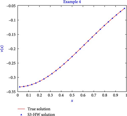
Figure 10 shows the S3-HW solution and true solutions for the level of resolution j = 1. The figures show that the resulting S3-HW solution coincides well with the true solution. Figure 11 shows the graph of absolute error for Example 4 when j = 1. The algorithm also took only 0.212 s to execute the fourth example program.

7. Conclusions
- (1)
Convergence and error reduction: as the level of resolution increases, the errors decrease, demonstrating the convergence of the S3-HW solution toward the exact solution.
- (2)
Higher accuracy with fewer grid points: the proposed method achieves a higher level of accuracy even with a small number of grid points, highlighting the reliability of this approach.
- (3)
High precision: the solution obtained through the method exhibits a level of accuracy up to 10−16 which can be further improved by increasing the level of resolution.
- (4)
Computational support and compatibility: the computational work seamlessly supports the proposed algorithm. Common subprograms can be utilized for calculating wavelet matrices and integrals of wavelets for all problems.
- (5)
Efficiency and low computation cost: the matrices associated with Haar Scale 3 wavelet collocation method, including wavelet matrices and their integrals, exhibit significant sparsity, resulting in faster computations and reduced computational costs.
- (6)
Effectiveness for linear and nonlinear equations: the S3-HW algorithm proves equally effective for both linear and nonlinear Lane–Emden equations.
- (7)
Superior performance: comparative numerical experiments reveal that the proposed method outperforms various other methods, establishing its superiority in terms of accuracy and efficiency.
- (8)
Potential for extension: the rapid convergence and high accuracy achieved by the proposed method provide a strong foundation for extending its application to solve a wide range of physical problems governed by fractional integro-differential equations and integral equations.
The primary drawback of the scale 3 Haar wavelet family is its discontinuity at the partition points, which renders the derivative approach inapplicable in the initial stage, which we tackled by converting the given differential model into the corresponding integral model. Additionally, the computational cost rises as the level of resolution increases. But the given method exhibits good accuracy at the initial level of resolution. The increase in the level of resolution requires for more complex problems, where one can compromise the computational cost to obtain good accuracy.
Conflicts of Interest
The authors declare that they have no conflicts of interest.
Acknowledgments
The authors are grateful to Lovely Professional University for providing the infrastructure needed to conduct their research.
Appendix
MATLAB Code for First Nine Members of Scale 3 Haar Functions
function o = nhaar (i)
o = zeros(size (i));
o (i > = 0) = 1;
o (i = = 1) = 0;
end
function o = haar2 (i)
o = zeros(size (i));
o (i > = 0) = −1/sqrt (2);
o (i > = 1/3) = sqrt (2);
o (i > = 2/3) = −1/sqrt (2);
o (i >1) = 0;
end
function o = haar3 (i)
o = zeros(size (i));
o (i > = 0) = sqrt (3/2);
o (i > = 1/3) = 0;
o (i > = 2/3) = -sqrt (3/2);
o (i >1) = 0;
end
function o = haar4 (i)
o = zeros(size (i));
o (i > = 0) = -1/sqrt (2);
o (i > = 1/9) = sqrt (2);
o (i > = 2/9) = -1/sqrt (2);
o (i >1/3) = 0;
end
function o = haar5 (i)
o = zeros(size (i));
o (i > = 0) = sqrt (3/2);
o (i > = 1/9) = 0;
o (i > = 2/9) = -sqrt (3/2);
o (i >1/3) = 0;
end
function o = haar6 (i)
o = zeros(size (i));
o (i > = 3/9) = -1/sqrt (2);
o (i > = 4/9) = sqrt (2);
o (i > = 5/9) = -1/sqrt (2);
o (i >2/3) = 0;
end
function o = haar7 (i)
o = zeros(size (i));
o (i > = 3/9) = sqrt (3/2);
o (i > = 4/9) = 0;
o (i > = 5/9) = -sqrt (3/2);
o (i >2/3) = 0;
end
function o = haar8 (i)
o = zeros(size (i));
o (i > = 6/9) = -1/sqrt (2);
o (i > = 7/9) = sqrt (2);
o (i > = 8/9) = -1/sqrt (2);
o (i >1) = 0;
end
function o = haar9 (i)
o = zeros(size (i));
o (i > = 6/9) = sqrt (3/2);
o (i > = 7/9) = 0;
o (i > = 8/9) = -sqrt (3/2);
o (i >1) = 0;
end
close all;
x = 0 : 0.000001 : 1;
figure (1)
subplot (3,1,1) % add first plot in 2 x 2 grid
plot (x,nhaar (x),’k’,’LineWidth’,2)
txt = ’i = 1’;
text (0.5,0.5,txt,’FontSize’,14)
axis([0 1 0.0 1.5])% line plot
%title (’First nine members of haar wavelet family h1 to h9 ’)
xlabel (’h_{1} (t)’,’FontSize’,14)
fprintf (’\n\n’)
subplot (3,1,2) % add first plot in 2 x 2 grid
plot (x, haar2 (x),’k’,’LineWidth’,2)
txt = {’i = 2,k = 0,j = 0,m = 1 i = m + 2k + 1’};
text (0.45,0.5,txt,’FontSize’,14)
xlabel (’h_{2} (t)’,’FontSize’,14)
subplot (3,1,3) % add first plot in 2 x 2 grid
plot (x,haar3 (x),’k’,’LineWidth’,2)
txt = {’i = 3,k = 0,j = 0,m = 1 i = m + 2(k + 1)’};
text (0.45,0.5,txt,’FontSize’,14)
xlabel (’h_{3} (t)’,’FontSize’,14)
figure (2)
subplot (3,1,1) % add first plot in 2 x 2 grid
plot (x,haar4 (x),’k’,’LineWidth’,2)
txt = {’ i = 4,k = 0,j = 1,m = 3 i = m + 2k + 1’};
text (0.45,0.5,txt,’FontSize’,14)
xlabel (’h_{4} (t)’,’FontSize’,14)
subplot (3,1,2) % add first plot in 2 x 2 grid
plot (x,haar5 (x),’k’,’LineWidth’,2) % line plot
txt = {’i = 5,k = 0,j = 1,m = 3 i = m + 2(k + 1)’};
text (0.45,0.5,txt,’FontSize’,14)
xlabel (’h_{5} (t)’,’FontSize’,14)
figure (2)
subplot (3,1,3) % add first plot in 2 x 2 grid
plot (x,haar6 (x),’k’,’LineWidth’,2) % line plot
txt = {’i = 6,k = 1,j = 1,m = 3 i = m + 2k + 1’};
text (0.3,0.5,txt,’FontSize’,14)
xlabel (’h_{6} (t)’,’FontSize’,14)
figure (3)
subplot (3,1,1) % add first plot in 2 x 2 grid
plot (x,haar7(x),’k’,’LineWidth’,2) % line plot
txt = {’i = 7,k = 1,j = 1,m = 3 i = m + 2(k + 1)’};
text (0.45,0.5,txt,’FontSize’,14)
xlabel (’h_{7} (t)’,’FontSize’,14)
subplot (3,1,2) % add first plot in 2 x 2 grid
plot (x, haar8 (x),’k’,’LineWidth’, 2) % line plot
txt = {’i = 8,k = 2,j = 1,m = 3 i = m + 2k + 1’};
text (0.45,0.5,txt,’FontSize’,14)
xlabel (’h_{8} (t)’,’FontSize’,14)
subplot (3,1,3) % add first plot in 2 x 2 grid
plot (x,haar9 (x),’k’,’LineWidth’,2) % line plot
txt = {’i = 9,k = 2,j = 1,m = 3 i = m + 2(k + 1)’};
text (0.45,0.5,txt,’FontSize’,14)
xlabel (’h_{9} (t)’,’FontSize’,14)
Open Research
Data Availability
The data underlying the results presented in the study are available within the manuscript.


