A Novel Transient Analysis of Multiterminal VSC-HVDC System Incorporating Superconducting Fault Current Limiter
Abstract
Power transmission using a voltage source converter- (VSC-) based high-voltage direct current (HVDC) system offers autonomous control of real and reactive power, constant DC voltage polarity, and bidirectional power flow. This helps to realize the multiterminal VSC-HVDC system and its integration into renewable energy sources to meet the growing power demand. However, there is a risk of higher voltages and currents during a DC line fault. The barrier to the advancements of VSC-MTDC systems is the nonavailability of commercial, higher-rated DC circuit breakers. This necessitates research on alternative methods of DC fault-clearing schemes with available technologies. In this direction, a superconducting fault current limiter (SCFCL) is an alternative option to mitigate the problems encountered in VSC-MTDC system operation. Because of this, there are not many VSC-MTDC systems available worldwide. This paper discusses different issues associated with the transient performance of the VSC-MTDC system. A representative case involving resistive SCFCL for DC line protection is presented. The simulations are carried out in the PSCAD/EMTDC platform.
1. Introduction
The increasing power demand in major cities and accessibility of power in isolated areas necessitates efficient power transmission methods. High-voltage DC transmission is an established method for transmitting power over greater distances and at higher capacity. The recent voltage source converter-based HVDC technology addresses the evolving power transmission market issues and challenges [1]. The VSC-HVDC systems are crucial due to their immunity to commutation failure, lower footprint, operation without telecommunication, and regulation of both active and reactive power independently [2]. These systems are suitable for renewable energy integration, supply of power to islands, remote region loads, feeding power to city centers, DC grid configurations, and improving system voltage stability and quality of power [3].
VSC-HVDC transmission is not suitable to withstand extreme overcurrents and overvoltages and is susceptible to failures during DC line faults. Because of this, underground cable systems and back-to-back systems are suitable for VSC-HVDC system applications, where DC line faults are not there. However, even in VSC-HVDC transmission networks using DC cables, the location, isolation, and point of occurrence of DC fault transients as well as the fault current contribution pose a substantial risk to the system’s functionality [4]. During DC faults, overcurrent and overvoltage stresses can damage the converter and system components. Insulated Gate Bipolar Transistors (IGBTs) [5] have a rated overcurrent and overvoltage capability of 2 pu [6]. A suggested fault-clearing scheme involves interrupting fault currents, blocking VSCs, and allowing fault currents to flow through overrated diodes. The protection of these technologies is crucial, and many researchers are looking into various methods to protect VSC-based point-to-point and MTDC [7] systems from DC line faults. The earlier papers suggest using controllers, AC and DC breakers/switches [8], and DC protective devices for satisfactory recovery, transient performance, and isolation during permanent DC faults [9–12]. These methods aim to overcome DC fault conditions and ensure reliable system performance.
Recent modular multilevel converter- (MMC-) based HVDC systems use full-bridge (FB) MMC or half-bridge (HB) MMC or a combination of both, for power transmission via overhead lines or DC cables [13]. The HB-MMC together with the HVDC breaker provides DC fault protection, while FB-MMC blocks DC fault current but cannot isolate it [14]. A study using a 4-terminal MMC-based mesh-type HVDC grid outlines the fault-clearing strategies and requirements for HVDC grid protection. Series inductors are suggested for fault current interruption by HVDC breakers, and a superconducting fault current limiter (SCFCL) can extend fault-clearing equipment time. The HVDC circuit breaker is expected to operate within 2 milliseconds of the occurrence of a fault. The study [15] explores the configurations, controls, and recovery conditions of the MMC-HVDC system based on overhead line, to address DC pole faults, in bulk power transmission.
HVDC circuit breakers with fast-acting mechanisms can effectively eliminate DC fault current and disconnect DC links during faults, but they are uneconomical and still in prototype status. The importance of commercial HVDC breakers, fault process, fault clearing times, DC breaker technologies, and their installations in real networks are discussed in [16]. The paper [17] proposes multiport DC circuit breakers (MPCBs) which significantly reduce the costs and footprints by component sharing and device integration and summarizes the economic and functional analysis along with technical requirements. The circuit breaker combined with a resonant current source (RCS) and a resistive superconducting fault current limiter (SFCL) as protection methods for the DC system are discussed in [18]. The method suggested can increase the length of the superconducting tape used and speed up the bubble diffusion during quenching in the MMC-HVDC-modeled grid. The paper [19] proposes a resistive-mechanical DC circuit breaker with a resistive superconducting element. Here a combined model is used to limit the initial fault current by quenching the resistive superconducting element. It also creates an artificial zero-crossing through the LC divergence oscillation circuit of the mechanical DC circuit breaker to perform safe fault protection.
From the above aspects, it is clear that there is a necessity to research, study, and design alternative HVDC circuit-breaking protection strategies using currently available technology and to extend these protection concepts to VSC-HVDC grid networks. In this context, an ultra-fast switching superconducting fault current limiter (SCFCL) can act as an attractive option. A previous paper [20] by the present authors proposed the DC protection method and application of using DC side SCFCL to control and limit overcurrents during DC transient conditions in the VSC-HVDC system and conducted a thorough investigation on resistive SCFCL, including material issues, the transient model, and its use in VSC-HVDC system to overcome the impact of dc faults in overhead lines. These research findings demonstrated the importance of SCFCL in suppressing transient overcurrents. Further studies in DC protection of point-to-point VSC-HVDC transmission systems are carried out with the applications of SCFCL and Chopper Controlled Resistors (CCR) to control the DC fault conditions [21].
The application of SCFCL integration into a multiterminal UHVDC system in India was studied in [22]. The study indicated the effectiveness and ability to clip the fault currents to lower values within half a cycle in the MTDC system. The concepts and applications of SCFCL in DC networks, modeling details, conceptual details, experimental and operational details, materials used, prototype test results, DC matrix SCFCL, their impact on circuit breakers, application in VSC-HVDC network with DCCB are explained in detail in [23]. Hence, SCFCL can be employed to overcome the challenges encountered in VSC-MTDC during transient fault conditions. As of date, multiterminal VSC-HVDC systems do not exist globally. A comprehensive system model based on multiterminal VSC converters is required to understand the complex controller behavior, steady state, and transient operation and to know commissioning requirements [24].
Simulation studies can investigate ground electrodes, transformer ratings, converter layouts, controls, and protection and losses occurring during transmission for different modes of operation. The focus of the present work is on the modeling and analysis of VSC-based MTDC systems integrated with resistive SCFCL (R-SCFCL) protection. The R-SCFCL is modeled in MATLAB and the VSC-MTDC system in a PSCAD/EMTDC environment, and transient fault studies are conducted. The postprocessing of results is done using MATLAB. The study aims to build VSC-MTDC models for various system studies, acquire knowledge about the transient behavior of the VSC-MTDC system, and build expertise for stable operation and reliable functioning of the system.
2. Analysis of the VSC-MTDC System
This section discusses the VSC-MTDC system details, the control strategy adopted, and the selection of different system parameters, and the SCFCL model for the system under study.
2.1. System Description
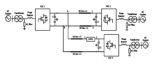
The schematic of the VSC-based multiterminal HVDC system with SCFCL, studied in this paper, is depicted in Figure 1. It is a three-terminal asynchronous radial connected VSC-HVDC (VSC-MTDC) overhead lines system. The three converters (VSC1, VSC2, and VSC3) are connected in parallel on the dc side. Reactors are connecting the three converters to individual AC grids. Thevenin’s equivalent circuit having impedance with equivalent voltage representation is used for the AC supply network. The converters are two-level VSC, 6 pulses, symmetrical monopole, operating at 1980 Hz PWM along with phase reactor, the DC link capacitor, the IGBT, and antiparallel diode. The center point of the DC capacitors of each converter is grounded. This is a fictitious system developed for the present study. It is modeled and analyzed for steady-state operation and transient behavior during AC fault conditions using a PSCAD/EMTDC environment.
2.2. System Parameters
The rating of each VSC-HVDC converter is twice the rated value of the transmission system. Any value above the maximum rating the VSCs have to be tripped; otherwise, it will break. In this study, the parameters of the system are considered such that the maximum total fault current with protective devices in the DC line is not more than 2 pu. This is done by considering the values of transformer reactance [25]. The converter-phase reactor serves the purpose of electrical measurements and also decreases the rate of rise of DC fault currents. The series DC side reactor on each VSC helps to reduce the ripple and DC fault current and manages charge across the DC capacitor. The DC line model is considered equivalent the T model [26]. The DC link capacitor at each VSC helps to maintain the steady DC bus voltage and avoids voltage collapse. Here, the value is considered based on the method suggested and the data given in [27]. The system adopted has ratings of 400 MW, ±200 kV, 1 kA, DC overhead lines: Line12 and Line13 are each 100 km in length. Each VSC can transmit power in either direction [28]. In steady state, VSC1 and VSC2 are in rectifier mode, drawing power from the AC grid and VSC3 is working as the inverter, feeding power (−400 MW) to the AC grid. The AC supply details are AC1: 420 kV, 60 Hz, AC2: 420 kV, 50 Hz, and AC3: 500 kV, 50 Hz.
3. Control Strategy for the MTDC System
Converter controllers significantly impact the dynamic behavior of the DC link. The different controllers used with each converter of the VSC-MTDC [29, 30] system are outlined in [31]. The controllers on each VSC are decided based on the function of each terminal and their connection, either passive or AC network, and whether strong or weak AC grid connection. The VSC converter station controller manages the assigned converter operating set-point, i.e., managing currents and voltages at AC and DC side terminals [32]. For the present system of three-terminal VSC-MTDC, the VSC1 (station 1) is functioning as the DC voltage controlling terminal, and converters 2 and 3 (VSC2 and VSC3) are configured to operate in active power mode of control [33]. Incorporating additional DC-side voltage control loops can ensure other stations handle faults and transient situations. Apart from this, all converters can work as either reactive power or AC voltage controls. The station operating on DC voltage will work as a battery/slack bus, providing or absorbing active power to maintain a power flow balance criterion in the DC system [34].
-
VSC1: controlling both DC voltage and AC voltage
-
VSC2: controlling of real power mode and AC side voltage
-
VSC3: controlling active power-mode and AC side voltage
The DC voltage regulation is assigned to the VSC1 station [35]. It performs two duties which are the first one is delivering power to achieve power flow equilibrium on the DC terminal, and the second one is delivering controlled DC side voltage at the set reference voltage [36, 37].
4. Superconducting Fault Current Limiter
The conventional FCLs in high-voltage networks pose several drawbacks, and the SCFCLs have distinct advantages, and comparative assessment details are explained in [38]. The different SCFCLs are Resistive SCFCL (R-SFCL) [39], Shielded Core Reactor Superconducting FCL (SCR-SFCL) [40], and Saturated Iron Core FCL (SIC-FCL) [41]. The main advantages of SCFCL applied to power networks present appealing technical and financial benefits. They provide negligible resistance while operating normally in a steady state, an incredibly quick changeover from a superconducting state to a normal conducting region, and negligible losses during working conditions making them cost-effective solutions [42]. Applications of SCFCLs in AC systems have shown successful field testing of prototypes and technology’s viability. SCFCL applications in DC networks have lesser losses due to two leads and DC-SCFCLs require lower-power refrigeration systems, making them compact and less expensive [43]. Quench current and resistance increase remain consistent as of AC type [44].
Resistive SCFCL (r-SCFCL) is proposed for power system applications due to its simplicity, ease of connection, and reduced inductiveness. Matrix-type SCFCL modules which are formed by series and parallel connections are suggested for transmission level voltages [45]. Studies on material aspects, prototype testing, and installations are given in [46]. High-temperature superconducting materials, including Bi2212, Bi2223, and Y123, are recommended for power applications at 77 K. The most resilient material is Bi2212 producing greater surface area artifacts, allowing higher ratings for FCLs. These materials have a strong temperature dependency and nonlinear E-J properties. The behavior of the HTS-type SCFCL device is governed by the nonlinear E-J characteristics which exhibit very strong temperature dependence [47]. The E-J characteristics exhibited by all HTS materials are shown in Figure 2.
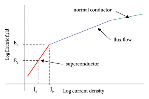
The E-J characteristics form the basis for modeling the behavior of R-SCFCL and simulation. The E-J characteristic exhibited by all HTS materials consists of 3 parts, viz., flux flow state, superconducting state, and normal resistive state, as shown in Figure 2 [48]. In the present work, the behavior of the SCFCL device is modeled using MATLAB code. The SCFCL model code consists of describing the mathematical model equations of the three states shown in E-J characteristics viz., flux flow state, superconducting state, and normal conductor state. The modeling and simulation of the R-SCFCL device are explained in [49] by present authors. The model used in the present paper is tested and validated using the suggested method, data, and results in [50]. For the sake of clarity, a few details are reproduced here.
4.1. Modeling and Analysis of SCFCL
The following procedures are involved in modeling the behavior of SCFCL [51]. Compute the current density in the SCFCL at each instant by knowing the cross-sectional area and the current flowing through the superconductor. Then, compare the electric field E (J, T) with E0. SCFCL is superconducting when E (J, T) < E0 and enters the flux flow state when E (J, T) > E0. Up to RFCL ≤ Rn, where Rn = ρ(95)Ln/S, and Ln and S are the length and area of a cross-section of the superconducting material, SCFCL remains in the flux flow condition [52]. The SCFCL is in a normal conducting state and provides the greatest resistance to the passage of current when RFCL > Rn. At every instant, the SCFCL’s resistance, temperature, voltage drop, and electric field are computed. The SCFCL ratings and parameters used in this paper are given in Table 1. Each SCFCL unit has a rating of 10 kV and 1 kA (both rms). To form the required rating of 200 kV, 1 kA, twenty such units are connected in series [53–55]. The MATLAB module of SCFCL is then interfaced with the VSC-MTDC system established in the PSCAD/EMTDC simulation tool using its interface facility [56].
| Parameter | Value |
|---|---|
| Rated voltage UN | 10 kV (rms) |
| Rated current IN | 1 kA (rms) |
| MVA SN | 10 |
| Initial operating temperature (T) | 77 K |
| Critical operating temperature (TC) | 95 K |
| Critical current density at 77 K (JC77) | 4e7 A/m2 |
| The electric field at the transition from superconducting to flux-flow state (E0) | 1 V/m |
| Critical electric field (EC) | 1.0e − 4 V/m |
| Length of superconductor (lSC) | 50 m |
| Superconducting region exponent at 77 K (α) | 12 |
| Flux-flow region exponent (β) | 2.4 |
| Cross section of superconductor (S) | 0.25e − 4 m2 |
| Normal conducting state resistivity (ρ) | 7e − 6 Ω-m |
| Self-inductance (Lsc) | 0.4e − 6 H |
| Shunt resistance (RSh) | 6 Ω |
5. Numerical Simulation and Results
The goal of the present paper is to evaluate the steady-state operation and transient behavior of the three-terminal radial VSC-MTDC system. Simulations are carried out and the behavior of each VSC converter is analyzed to achieve satisfactory performance of the entire system. The system is assessed with different parameters like each converter’s DC terminal voltages, DC side currents, and real and reactive power flow control, their direction and DC link power transmitted are analyzed. The operation of VSC-MTDC for steady-state, AC faults single phase-to-ground fault, and three-phase grounded fault states are simulated and analyzed. For the single line-to-ground fault condition the DC side voltage control reference change is introduced and studied to avoid the power flow reversal and loss of converter situation in the system, and recovery of the system is analyzed. A representative case of DC protection using SCFCL is presented, simulated, and analyzed for transient behaviour under a 3-phase grounded fault created at the AC bus of VSC3. This system is analyzed without and with SCFCL protection without considering the impact of the HVDC circuit breaker. The different AC faults are created at 1.2 sec (after reaching a steady state) lasting for 3 cycles (0.06 sec).
5.1. Steady-State Operation of the System
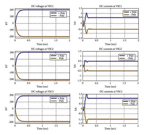
Three terminals VSC-based MTDC models are developed in the PSCAD/EMTDC simulation environment. Initially, the VSC-MTDC system is simulated for time steps ∆t = 50 μs and ∆t = 25 μs to achieve the satisfactory operational performance of the system and to select proper time step and power balance condition is evaluated for the DC voltage controlling terminal and also to reduce the steady state losses occurring in the system. The simulation cases presented here are based on time step ∆t = 50 μs. Figure 3 depicts the results of steady-state operation in terms of DC voltages and DC currents of the system measured on the DC side of individual VSC converters. The DC voltages of VSC1, VSC2, and VSC3 and DC currents at VSC1, VSC2, and VSC3 are plotted. The simulations are carried out for 2 sec. From the result curves, it is observed that there are transients in the initial period, and these transients are subsided within a few cycles in 0.25 sec, and the system reaches steady-state conditions. The steady-state operating DC voltages and DC currents of each VSC are summarized in Table 2 from the result curves of Figure 3.
| VSC1 terminal | 200 kV | 0.58 kV |
| VSC2 terminal | 204 kV | 0.49 kV |
| VSC3 terminal | 190 kV | 1.6 A |
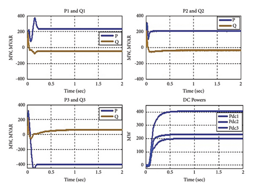
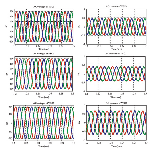
Figure 4 shows steady-state values of active and reactive power and the magnitude of dc powers at each VSC. The simulations are carried out for 2 sec. From the result curves, it is seen that the initial period transients are subsided within 0.25 sec. The steady-state values of the system were obtained. The power exchange at the DC bus and the AC side real power exchange at the point of common coupling will be the same in steady-state operation. Figure 5 shows the graphs and values for steady-state AC bus voltages and AC currents on the AC utility side of each VSC station. Each VSC can transmit power in either direction, from the result curves, it is seen that, in steady state, the power transmission of VSC1 and VSC2 (each about 200 MW) in rectifier mode and drawing power from AC grid and VSC3 is working as Inverter mode and feeding power (−400 MW) to the AC grid. The steady-state AC voltages are AC1: 420 kV, AC2: 420 kV, and AC3: 500 kV. The study focuses on SCFCL protection to reduce overvoltages and currents without considering the HVDC breaker operation, studies with circuit breaker operation will be addressed separately.
5.2. Single Line-to-Ground Fault (SLGF) on AC Utility of VSC3
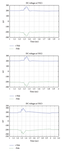
Because of analyzing unbalanced conditions in VSC-based MTDC, single-line-to-ground fault SLGF is created on phase A of the grid side of VSC3 at t = 1.2 sec, fault lasting for the duration of 3 cycles (0.06 sec). The entire system simulations are carried out for 2 sec. Initially, for the present three-terminal VSC-MTDC case discussed in the present paper, VSC converter 1 (VSC1) is working in DC voltage control mode, operating as a rectifier, and stations 2 (VSC2) are functioning as a rectifier, and station 3 (VSC3) is operating in inverter mode. Both VSC2 and VSC3 are in control of active power mode. The system performances under SLGF are given in Figures 6, 7, 8, and 9. When a fault is created at t = 1.2 sec, it is observed that there is a rise in DC voltages (Figure 6) at all three VSC stations.

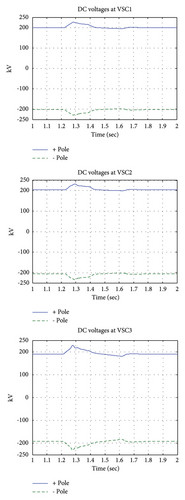
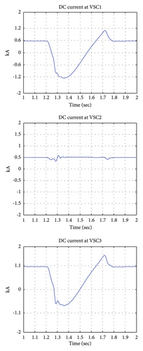
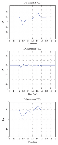
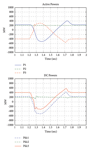

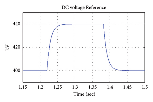
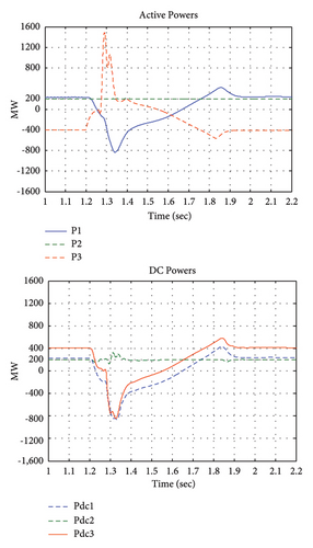
The dc currents increase rapidly (Figure 7) at stations 2 and 3. Both values are reaching approximately 2 pu of rated values of currents which can damage the VSCs if not blocked. Whereas from Figure 8 (active powers and DC powers), it is observed both the converters VSC1 and VSC3 lose their initial operating points there is a loss of converter station situation and there is power reversal occurring in the VSC-MTDC system. After the fault duration, the system recovers. In the literature, to avoid loss of converter situation control methods called voltage margin method and DC voltage droop control were proposed where multiple VSC stations operating to control DC voltage to achieve stable operating conditions. When there is a loss of converter station situation in the multiterminal VSC-HVDC there are either voltage dips or voltage spikes. In this study, the authors have studied the method to control the temporary loss of VSC stations from their operating points by way of the DC voltage reference change method. From Figures 8 and 9, it is observed that when there is a power reversal situation during fault duration and when the set reference value of DC voltage is changed then the power reversal situation, i.e., loss of converter station is avoided and the current spikes also reduced leading to early recovery of the system. Here, the set reference value for the DC voltage controller is assigned to a 10% higher value, i.e., 440 kV (1.1 pu) instead of 400 kV (1 pu).
5.3. Three-Phase Ground Faults on AC Utility of VSC3
5.3.1. Without SCFCL Protection
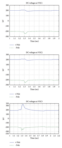
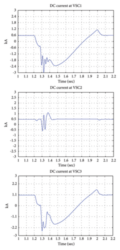
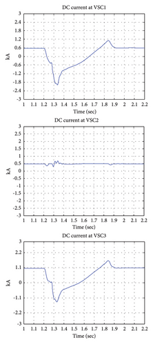
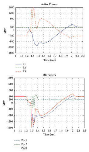
A three-phase-to-ground fault is the greatest severe fault. In the present study, the fault is created at 1.2 sec of duration for 3 cycles. Figures 10, 11, and 12 show the simulation results of DC voltages, DC currents, and different powers, respectively, during faulty conditions without and with SCFCL included. When three three-phase to-ground faults occur, there is a three-phase short circuit in the system leading to the discharging of DC capacitor currents into the ground. During the three-phase to ground fault, the entire system is in an unbalanced condition due to both spikes in DC voltages and rapid rise in DC currents. This disturbs the output of the DC system and power transmission through the DC link and temporary loss of converter and reversal of power through the system.
5.3.2. With SCFCL Protection
To limit the overcurrents and to overcome the severe conditions of a three-phase-to-ground fault a resistive SCFCL integrated into the VSC-MTDC system is shown in Figure 1. The response of VSC-based MTDC system without and with SCFCL protection is evaluated. Figure 13 shows the SCFCL temperature and resistance behavior during transient conditions.
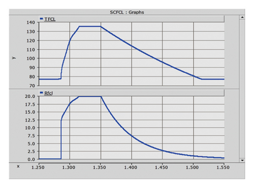
For the case of SCFCL, it is observed that, with the rise in the current due to fault, the SCFCL temperature increases and it losses superconductivity and transits to a normal state. This introduces a resistance in the circuit which cuts the first peak of the fault current. The peak value of DC at the positive pole of VSC1 is clipped from −3 kA (without SCFCL) to −1.8 kA (with SCFCL), and the maximum value of DC voltage with SCFCL is reduced from 260 kV to maintains at 200 kV (steady-state value), at VSC2 positive pole the dc peak value of current of 1 kA is reduced to 0.6 kA, DC voltage is reduced from 290 kV to maintains at 200 kV. At the VSC3 terminal without SCFCL, the peak values of current and DC voltage are −2.5 kA and 300 kV and with the peak values are limited to −1.3 kA and DC voltage is about 300 kV. Subsequent peaks are also clipped as observed in Figures 10, 11, and 12. A similar variation is seen for the negative pole current and is indicated in Figures. From Figure 13, it is observed that with DC protection SCFCL the reversal of powers is controlled and the VSC-MTDC system recovers in the first few cycles. The results indicate the usefulness of SCFCL in limiting DC currents during DC faults and as an alternative DC protection device to VSC-MTDC system operation.
6. Conclusions
In this work, the detailed modeling, simulation, and transient analysis of a multiterminal HVDC based on VSC, focuses on control strategy and parameters for satisfactory operating conditions. The study developed a multiterminal VSC-HVDC model for power system studies and provided insight into the system’s operational characteristics. The performance of VSC-MTDC in terms of steady-state operation, single line-to-ground fault, and three-phase-to-ground fault conditions are presented. In the present study, results show that a simple method of DC voltage controller reference change for SLGF condition loss of converter behavior can be avoided and also investigates the use of SCFCL device in voltage source converter-based MTDC system to overcome higher current and voltage stresses during three phase ground fault on AC utility. Hence, SCFCL can be an attractive alternative DC protection for the VSC-MTDC system. Further, using the VSC-MTDC system and SCFCL model studies will be carried out to analyse the behaviour of SCFCL devices in the VSC-MTDC system to overcome the severe DC line fault conditions.
Ethical Approval
This paper does not contain any studies with human participants or animals performed by any of the authors.
Disclosure
Authors transfer to Wiley the publication rights and warrant that our contribution is original.
Conflicts of Interest
The authors declare that they have no conflicts of interest.
Authors’ Contributions
All authors contributed to the study, conception, and design. All authors commented on the manuscript. All authors read and approved the final manuscript.
Open Research
Data Availability
The datasets used and analyzed during the current study are available from the corresponding author upon reasonable request.


