A Finite-Time Fractional-Order Error Extended State Observer for Hypersonic Vehicle
Abstract
To address the challenges posed by strong coupling, nonlinearity, and rapid time-varying dynamics in hypersonic vehicle (HV), this study presents an active disturbance rejection control (ADRC) scheme based on finite-time fractional-order error extended state observer (FTFOEESO). To begin, a control-oriented HV model is established. Subsequently, the FTFOEESO is developed to accurately estimate and compensate for strong disturbances and uncertainties. Unlike traditional FOESO, this observer does not alter the physical interpretation of the estimated variables or introduce unknown disturbances. Furthermore, this approach has demonstrated significant potential in mitigating high-frequency noise. Theoretical analysis has confirmed that the observation error of FTFOEESO is uniformly bounded. Finally, this paper conducts experiments using both conventional simulation and semiphysical simulation systems. Simulation studies and comparisons have revealed that the ADRC based on FTFOEESO possesses superior anti-interference and antinoise capabilities.
1. Introduction
The rapid development of hypersonic vehicle (HV) technology has attracted widespread attention from researchers due to its exceptional speed, maneuverability, and wide flight envelope [1–3]. However, the complex dynamics of HV, characterized by strong nonlinearity, coupling, and fast time-varying dynamics, pose significant challenges to the safety and reliability of flight [4, 5]. Moreover, exposure to radiation and mechanical vibration during flight can introduce measurement noise, further impacting the reliability of the vehicle [6]. Therefore, the adoption of advanced flight control laws is crucial to ensuring the safe operation of HV.
To date, various advanced control theories have been utilized in the design of control systems for HVs. These include robust control [7, 8], sliding mode control [9, 10], model predictive control [11], and backstepping control [12, 13]. Although significant progress has been made in the control methods of HV, these methods have limitations in their practical application due to their reliance on models [14] or chattering near equilibrium points [15].
Active disturbance rejection control (ADRC), introduced by Professor Han [16], has gained significant traction across various domains owing to its model-independent nature and robust anti-interference capabilities [17–20]. As a typical control framework, ADRC utilizes extended state observer (ESO) estimation and compensation for disturbances [21], combined with feedback control to effectively improve the system’s disturbance rejection performance. To further enhance control performance, many studies have made improvements to ADRC [22–24], and one effective method is to introduce FOPID into the framework. Gao et al. have effectively integrated the merits of FOPID and ADRC to devise the fractional-order ADRC (FOADRC) approach for HV [25]. Simulation results demonstrate that FOPID-based ADRC outperforms traditional PID-based ADRC in terms of speed, accuracy, and robustness.
Recent developments in FOPID suggest that the potential for combining fractional-order operators with state observers is enormous. For example, Naderolasli, Hashemi, and Shojaei have proposed the fuzzy fractional-order state observer to estimate the unavailable states, which can converge the tracking error to around the origin without the need to measure all the system’s states [26]. Meanwhile, several studies have investigated the use of fractional-order ESO (FOESO) to explore the potential to significantly improve error estimation performance [27, 28]. Chen et al. have successfully used FOESO to compensate for total disturbances in an integral-order system, achieving better performance than traditional integral-order ESO [28]. However, most of these studies have focused on applying FOESO to fractional-order systems, and its potential for integral-order systems remains largely unaddressed. And it should be noted that traditional FOESO alters the physical meaning of total disturbance, introducing complex dynamics into the estimation results.
As an advanced aircraft with exceptionally high dynamic performance, the control system of HV needs to rapidly converge to meet stringent task requirements. Therefore, studying finite-time FOESO for HV is of significant importance. In this context, Naderolasli, Shojaei, and Chatraei utilize the terminal sliding mode disturbance observer on the basis of traditional sliding mode observers to estimate the speed of the leader in the formation, achieving finite-time convergence [29]. However, it should be noted that as the initial state of the system grows infinitely, the convergence time of TSMO also tends to infinity, thereby somewhat restricting its practical applicability [30]. Moreover, the team also has studied high gain state observers, which can effectively reduce convergence time and estimation errors by combining finite-time stability terms [31]. Nevertheless, all the aforementioned studies do not consider the finite-time convergence of FOESO.
- 1.
Compared with the traditional FOESO proposed in Ref. [27, 28], the proposed FTFOEESO preserves the physical interpretation of the estimated variables and the integral sequence structure, ensuring finite-time system convergence without introducing new unknown disturbances.
- 2.
This paper utilizes the new FTFOEESO to estimate and compensate for the coupling term between the three channels of HVs, achieving complete decoupling of the aircraft. And compared with Ref. [6], it improves the convergence speed of the control system.
- 3.
Successfully applied the FTFOEESO algorithm to a semiphysical simulation system, achieving effective suppression of high-frequency noise in engineering.
The structure of the remaining sections is as follows: Section 2 establishes a control-oriented HV model; the third section introduces the design of FTFOEESO and proves that the observer can achieve finite-time convergence of errors; Section 4 presents the comparison and verification of the algorithm’s control performance; finally, the conclusion can be found in Section 5.
2. Problem Formulation
This study centers around the winged-cone HV model initially proposed by Shaughnessy. To meet the specific research objectives, certain modifications have been made to the mass, rotary inertia, and geometric characteristics of the vehicle. The adjusted parameters are listed in Ref. [6].
2.1. Nonlinear HV Model
2.2. Linearized HV and Disturbance Model
Utilizing the nominal nonlinear HV model and considering the aerodynamic forces and moments, we establish the linearized HV attitude model.
Apparently, the linearized HV attitude control system can be divided into three individual second-order subsystems. And each subsystem will be impacted by multisource interference.
3. FTFOEESO-ADRC-Based HV Attitude Control System
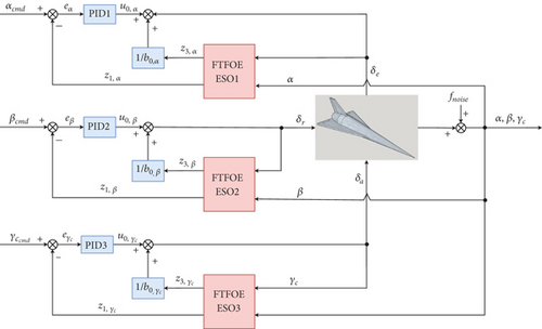
The main goal of this section is to develop an ADRC controller for HV based on FTFOEESO. In order to ensure the stability of the HV’s attitude dynamics, the control variables, namely, the angle of attack, sideslip angle, and velocity roll angle, are carefully selected and incorporated into the control design. The control scheme is visually depicted in Figure 1, providing a comprehensive overview of the proposed ADRC-based control architecture for HV attitude control.
3.1. Some Definition and Lemmas
Lemma 1 (see [30].)The system is said to be finite-time input-to-state stable (FT-ISS) in a finite-time T with respect to δ, where ‖δ‖ ≤ σ, if the inequality for functions f1 and f2 is guaranteed for any t ≥ t0 + T:
Definition 1 (see [32].)The gamma function is defined as
The fractional-order parameter α ∈ (0, 1).
Definition 2 (see [32].)The Mittag-Leffler function is defined as
And the k-th order derivative of the Mittag-Leffler function can be represented as
Definition 3 (see [33].)The Caputo fractional derivative is defined as
3.2. FTFOEESO Design
At this point, FTFOEESO has been designed and completed.
3.3. Asymptotic Convergence Analysis
Theorem 1. The FTFOEESO observation error converges to zero under constant total disturbance if and only if γ > 2/3.
Proof 1. For System (32), the transfer function matrix can be obtained via the Laplace transformation:
Rearranging and analyzing Equation (31), we find
Since the observation error can only converge to zero if the integral order of the pole polynomial is higher than that of the zero polynomial, which ensures that the observation error can approximate a constant signal when the total disturbance changes slowly, we have
Thus, when γ > 2/3, the observation error can converge to zero and the System (32) is stable.
Theorem 2. Define q = 1/(1 − γ). If q is integer, the System (22) is stable.
Proof 2. Since q = 1/(1 − γ), can be expanded as follows:
We can get
The extra states are the fractional-order differential of integral-order states. Therefore, the transfer function matrix of τ can be expressed as
Since System (38) is derived from a linear transformation of System (32) and System (32) is stable, System (38) is also stable.
The relationship between and τ can be expressed as follows:
The solution of Equation (38) can be expressed as
Combining the above transformations, we can get
Then, the FTFOESO is applied to HV control system, which is an integral-order differential system. The fractional-order differential states are obtained by numerical method. Therefore, the initial states of fractional order can be considered as zero. The inequality (42) can be expressed as follows:
Based on the transformation , one obtains
Thus, based on Lemma 1, the stability of System (22) has been proven.
3.4. Analysis of the Influence of Parameters
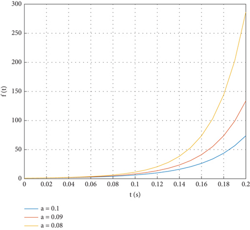
As shown in Figure 2, the smaller the value of the adjustment parameter a is, the greater the rate of increase in the time-varying function f(t), resulting in a swifter convergence speed for FTFOEESO.
4. Simulation and Experimental Analysis
In this section, simulation comparative experiments are conducted to verify the control performance based on FTFOEESO under nominal conditions, disturbance conditions, and high-frequency noise conditions. To ensure fairness in comparison, all control system parameters are kept consistent, and the controller parameters are designed using a nonlinear parameter optimization method [25]. The expecting amplitude margin and phase margin are set as 8 dB and 45°, respectively. The controller parameter design is presented in Table 1.
| Parameters | Roll channel | Pitch channel | Yaw channel |
|---|---|---|---|
| kp | 82.13 | 198.68 | 74.94 |
| ki | 10.14 | 1.65 | 0 |
| kd | 20.09 | 19.39 | 17.39 |
Additionally, the initial state of the HV control system is V = 15 Ma, y = 33, 500 m, and γc = 1°, while all other states are zero. The reference signal of attack angle and speed roll angle is set as 5°. And the desired sideslip angle is zero.
4.1. Nominal Conditions
Given the requirement for HV to have rapid response capabilities, the simulation duration for experimentation was set to 2 s. The corresponding results are illustrated in Figures 3, 4, and 5.
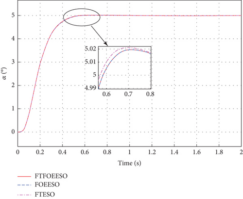
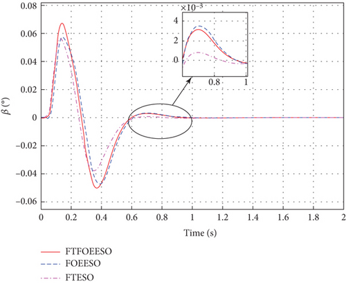

Based on Figures 3, 4, and 5, it is evident that the FTFOEESO-based ADRC system achieves stable control of HV successfully. While the control performance may be slightly lower compared to traditional FOEESO, there is a slight improvement in convergence speed, thereby validating the convergence capabilities of the proposed FTFOEESO to some extent. However, despite the advantages of the proposed method, the performance of FTESO remains more favorable under nominal conditions.
4.2. Disturbance Conditions
To validate the robustness of the system, the external disturbance is applied.
The rest of the conditions remain unchanged, and the results are showcased in Figures 6, 7, and 8.

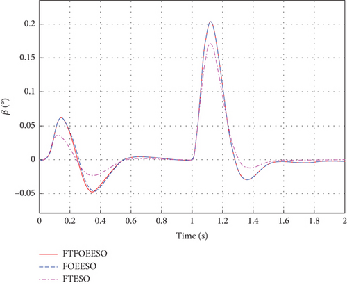

From the observations in Figures 6, 7, and 8, it is evident that the FTFOEESO-based ADRC system effectively mitigates the effects of disturbances on the system, thereby ensuring the stability of hypersonic aircraft attitude. Due to the strong coupling within the aircraft, even though disturbances are introduced only in the pitch channel, disturbances of varying magnitudes are generated in both the roll and yaw channels. However, ESO enables rapid compensation for these disturbances. Furthermore, FTFOEESO exhibits a slightly improved convergence speed compared to FOEESO.
4.3. High-Frequency Noise Conditions
The simulation conditions are consistent with those mentioned above. Besides, a sine wave fn = 0.1°sin40πt is applied to pitch channel as measurement noise. Figures 9, 10, and 11 display the simulation results.
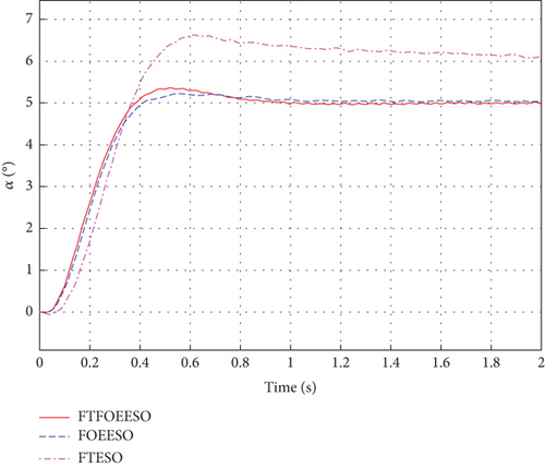
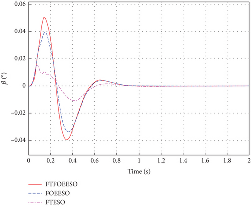
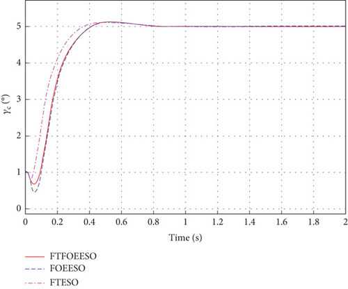
As depicted in Figure 9, the closed-loop control system of HV utilizing FTFOEESO-ADRC and FOEESO-ADRC exhibits enhanced resilience against high-frequency noise, shorter stability time, and reduced steady-state error when compared to FTESO-ADRC. The steady-state error is 80% smaller than that of FTESO. Additionally, Figures 9, 10, and 11 illustrate that FTFOEESO demonstrates a faster convergence speed than FOEESO, indicating its advantages in terms of noise resistance and convergence speed.
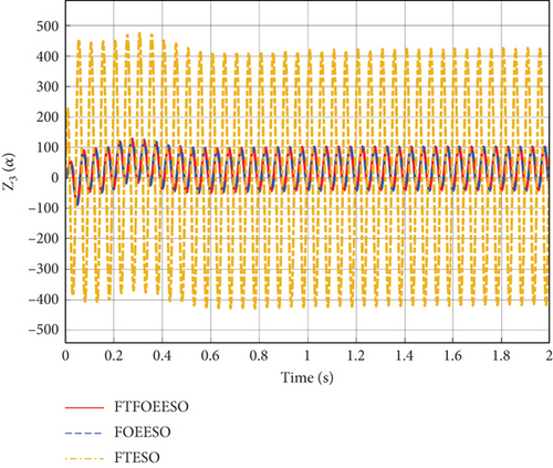
The estimation of the lumped disturbance is presented in Figure 12. It is evident that FTFOEESO successfully mitigates the influence of measurement noise on the total disturbance estimation. And it can be concluded that FTNFOESE exhibits superior anti-interference and antinoise capabilities compared to FTESO.
4.4. Semiphysical Simulation Verification
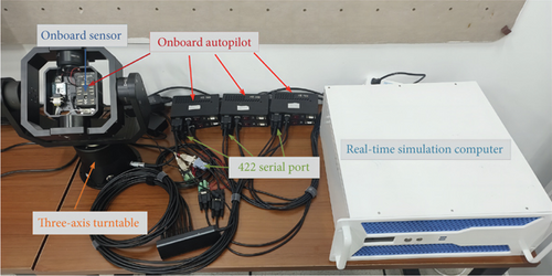
As shown in Figure 13, the hardware in the loop simulation system consists of onboard sensor, onboard autopilot, three-axis turntable, and real-time simulation computer.
The control period of the flight control is 0.001 s, and the parameters of the controller are set according to Table 2.
| Parameters | Roll channel | Pitch channel | Yaw channel |
|---|---|---|---|
| kp | 35.6616 | 45.4184 | 17.5936 |
| ki | 0.8764 | 1.1374 | 0 |
| kd | 9.4103 | 11.731 | 4.3911 |
To verify the robustness of FTFOEESO, a high-frequency noise as mentioned earlier is applied to the system. Experiments have revealed that during the hardware-in-the-loop simulation process, FTESO is prone to divergence when the noise amplitude is large. To ensure a more equitable comparison in the experiment, the amplitude of the noise is reduced to prevent the divergence of FTESO. And the experiment is shown in Figure 14.
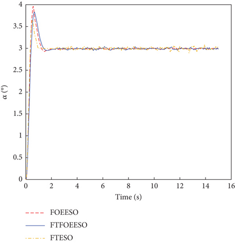
Based on the observation from Figure 14, it is evident that while FTESO exhibits fast convergence with minimal overshoot, it falls significantly short in terms of noise suppression compared to FTFOEESO and FOEESO. Conversely, the ADRC utilizing FTFOEESO showcases superior performance in terms of faster convergence speed and smaller overshoot, without a significant difference in noise suppression ability compared to FOEESO.
To further ascertain the observer’s performance, the mean error was employed as a metric to evaluate the noise suppression capability of each observer after introducing noise. The corresponding results are presented in Table 3.
| FTFOEESO | FOEESO | FTESO | |
|---|---|---|---|
| Mean error | 0.0095 | 0.0126 | 0.0198 |
It is observed from Table 3 that the noise resistance of FTFOEESO has experienced a reduction of 34.4% in comparison to FOEESO. However, this decrease in noise resistance has only resulted in a marginal increase of 0.0031 in the overall mean error. Consequently, this increment can be considered negligible. Therefore, it can be concluded that FTFOEESO enhances the system’s convergence speed and dynamic performance while making only a minor sacrifice in terms of noise resistance performance.
In conclusion, this implies successful achievement of stable control for HV through hardware-in-the-loop simulation, signifying the practicality and applicability of the algorithm in engineering scenarios.
5. Conclusion
This paper introduces an ADRC method based on FTFOEESO to address the high dynamics and fast time-varying characteristics of HV. Firstly, the three channels of the HV are simplified and decoupled, dividing them into three second-order subsystems for easier control system design. Subsequently, FTFOEESO is designed and incorporated into the ADRC framework, and a controller is designed for HV, demonstrating the uniform boundedness of FTFOEESO. Lastly, in addition to the conventional simulation, the paper also employs a hardware-in-the-loop simulation system to demonstrate the effectiveness of the proposed algorithm. Compared to the traditional FTESO and FOEESO, simulation results indicate that although FTFOEESO’s dynamic performance is slightly lower than FTESO’s, it ensures stable attitude in noisy conditions. Additionally, it enhances FOEESO’s convergence speed without compromising noise resistance. Therefore, adopting FTFOEESO can effectively enhance the system’s performance in complex environments. Furthermore, the design of FTFOEESO and its degenerate form, FOEESO, utilizes only two free parameters. In future research, we aim to further explore the potential performance of FOEESO.
Conflicts of Interest
The authors declare no conflicts of interest.
Funding
This work was supported by Key Laboratory of Spacecraft Design Optimization and Dynamic Simulation Technologies, Ministry of Education, Beihang University.
Acknowledgments
The authors thank the colleagues for their constructive suggestions and research assistance throughout this study.
Open Research
Data Availability Statement
The data that support the findings of this study are available from the corresponding author upon reasonable request.


