Research on Shortest Path Planning and Smoothing Without Obstacle Collision Based on Moving Carrier
Abstract
In response to the challenges of path planning in complex scenarios, to overcome the influence of optimal path determination by the precision of grid map sizes, and to escape the uncertainty in solving by intelligent algorithms, this paper designs a method for obtaining an adjacency matrix based on node planning of shortest path diagrams with polygonal obstacles and then uses the Dijkstra algorithm to get the shortest path. For irregular curved obstacles, an edge straightening method is proposed. To enhance the applicability of the path, this paper introduces the constraint of minimum turning radius. It researches path smoothing under obstacle conditions based on arcs and straight lines, providing practical solutions for different scenarios. Considering the need to maintain a safe distance due to the size of the moving carrier and the deviation in trajectory tracking, this paper conducts an expansion analysis of obstacles. It obtains the trajectory on the arc after edge straight line fitting, followed by further smoothing treatment. The method proposed in this paper demonstrates excellent accuracy and robustness in path planning through simulation verification, proving its practicality and effectiveness in complex environments.
1. Introduction
Path planning is a widely researched field that plans a collision-free path from a starting point to a destination. It is extensively applied in areas such as robot navigation, autonomous driving, logistics distribution, aerospace, game development, and traffic management. Due to its broad applications, researchers have paid high attention and achieved fruitful results. For path-planning problems with multiple obstacles, traditional algorithms include the A∗ algorithm [1], the Dijkstra algorithm [2], and the Bellman–Ford algorithm [3]. These algorithms perform well on small-scale problems but face issues with excessive computation time on large-scale problems. They all require grid processing of the map, and as the map size increases, the grid size cannot be increased, leading to a sharp increase in computation time and memory usage. Therefore, in recent years, researchers have started to focus on more efficient and intelligent path-planning algorithms, including ant colony optimization [4], particle swarm optimization (PSO) [5], genetic algorithms (GA) [6], simulated annealing [7], neural network algorithms [8], and rapidly-exploring random trees (RRT) algorithm [9]. Some of these intelligent algorithms require initialization of certain parameters and are sensitive to them, and the results generated each time are not unique, belong to local optima, and cannot be proven to be global optima. Some intelligent algorithms often struggle to find optimal paths like those passing through a “gourd mouth” because the probability of detecting such optimal paths is relatively low, resulting in performance that is often worse than traditional path planning algorithms.
Different planning methods are often used for different obstacle types. For polygonal obstacles, the Voronoi diagrams [10] are used for path planning, which, although safe, involves heavy computation and is not optimal. If the intervals between obstacles are large, the length of the generated path will increase significantly. For circular obstacles, artificial potential fields [11] are commonly used, setting appropriate penalty functions near obstacles to keep the planned path away. However, overlapping fields can make path planning difficult if obstacles are close together. Moreover, these algorithms require recalculation when the starting or ending point changes, making it hard to utilize previous results. To address these issues, some scholars have introduced new biomimetic algorithms for planning and design, such as the artificial fish swarm algorithm (AFSA) [12, 13] and the artificial bee colony algorithm [14]. These algorithms can perform parallel computation, have strong global search capabilities, and are less sensitive to initial value settings with a higher tolerance for parameter settings. These studies can obtain feasible solutions, but the results are not unique each time.
Smoothing issues are introduced to make the planned route more suitable for second-order dynamic systems. Smoothed paths are continuous in both direction and curvature, and theories such as Bezier curves [15], B-spline curves [16], and polynomial curves [17] are generally used to smooth the planned path. For aircraft, the smoothness of the route is crucial for improving flight performance and avoiding potential dangers, especially for high-speed aircraft, as it ensures stable flight posture and effectively enhances flight performance and safety [18]. Song, Wang, and Zou proposed a new scheme combining PSO with cubic Bezier curves to provide a smooth, optimal path for mobile robots, but it is difficult to guarantee the high-order continuity of the connected path segments [19]. Lekkas and Fossen [20] addressed two interrelated problems of vehicle planar three-degree-of-freedom motion (i.e., path planning and heading problems) by designing paths using monotonic cubic Hermite spline interpolation (CHSI) technology, avoiding oscillations and twists between two consecutive waypoints. Although path smoothing solves the continuity of direction and curvature during the following process, it does not consider the constraint of the minimum turning radius of the mobile carrier. The smoothed trajectory may be suitable for some mobile carriers but not others. In the presence of obstacles, the smoothed trajectory may become impassable. In practical applications, route smoothing must consider these two factors. The aforementioned smoothing theory mainly focuses on route smoothing and curvature continuity issues, often applied in low obstacle density scenario. When there are constraints on the curvature of the smoothing curve or when the obstacle density is high, it can lead to analytical difficulties. An effective way to handle route smoothing with curvature constraints is the circular arc and straight line smoothing algorithm [21], which fits a set of given points by minimizing errors, making the fitted curve (usually a combination of circular arcs and straight lines) as close as possible to these points. A widely used circular arc and straight-line smoothing algorithm is Dubbin’s curve [22], which considers the minimum constraint factors during the turning of the mobile carrier. However, the smoothed curve is constrained by obstacles, mainly because it deviates significantly from the original route, making it likely for the smoothed circular arc to collide with obstacles. We aim to achieve route smoothing through the combination of circular arcs and straight lines while considering the constraints on route curvature and the secondary obstacle avoidance issues brought about by changes in the route.
This paper adopts the shortest path map to find the optimal path through “gourd-shaped” bottlenecks and reduce the significant computational load caused by recalculating when the starting or ending points of the path change [23–27]. This approach effectively avoids the large computational and storage costs associated with map gridding and the suboptimal path problem arising from the increased area of obstacles due to gridding. The computational and storage requirements are only related to the number of vertices of the polygonal obstacles [27]. The basic algorithmic process treats the mobile carrier as a particle that can move along the edges of obstacles. An adjacency matrix is constructed based on the vertices of the polygonal obstacles, and the Dijkstra algorithm is used to obtain the shortest path. One of the contributions of this paper is the design of a method to get the adjacency matrix. For irregular obstacles (composed solely of curves or a combination of curves and straight lines), edge straightening is performed to expand them into polygonal obstacles, and the shortest path is analyzed based on the vertices of these polygonal obstacles. The paper provides methods for fitting circular and elliptical obstacles. After obtaining the shortest route, a path smoothing algorithm is designed based on the turning radius, using arcs and straight lines to ensure that the smoothed path closely follows the shortest path. Considering that actual mobile carriers are not point masses but have dimensions, for ease of analysis, their shapes are converted into circles based on certain rules, obtaining their centers and radii, and then a safe distance is calculated. After expanding the obstacles and approximating them with arcs and straight lines based on the safe distance, the shortest path is obtained and smoothed using the methods above. The feasibility and effectiveness of the algorithm are verified through simulation experiments. The paper is divided into four principal sections. The initial segment elaborates on constructing an adjacency matrix derived from mapping, facilitating determining the shortest path. Proceeding to the second segment, the investigation delves into smoothing linear trajectories, employing a combination of straight lines and circular arcs. The third segment addresses the smoothing of the shortest path in the context of real-world scenarios, postinflation of obstacles. Conclusively, the theoretical concepts are substantiated through experimental validation. A preprint of this article has been posted at Research Square [28].
2. Constructing an Adjacency Matrix From Obstacle Corner Points
2.1. Constructing Adjacency Matrix Based on Polygonal Obstacle Corner Points
Step 1: Determining the inner and outer boundaries of obstacle nodes.
Since the nodes on the obstacle are determined by their two mutually connected edges, to judge whether a line segment emanating from a node on the obstacle is inside or outside the obstacle, one can first calculate the polar angles of these two edges relative to the node, assuming the polar angles are θ1, θ2, with θ1 < θ2. Then, based on the node, draw a ray with a polar angle of λθ1 + (1 − λ)θ2, where 0 < λ < 1, and initially let λ = 0.5. Count the number of intersections of this ray with the edges of the obstacle. If the intersection is in the middle of an edge rather than on a node, count it as 1; if it is on a node, count it as 0.5. Then, analyze the sum of the intersection points for each edge. If it is odd, as shown in Figure 1(a), it indicates that the initial segment of the ray is inside the obstacle, and the polar angle range for the obstacle for this node is [θ1, θ2]; if it is even, as shown in Figure 1(b), it indicates that the initial segment of the ray is outside the obstacle, and the polar angle range for the obstacle for this node is (−π, θ1]⋃[θ2, π]. Some special cases do not satisfy this characteristic, mainly when the intersection points are on the corner points of the obstacle, as shown in Figures 1(c) and 1(d), in which case the above rules do not apply. There are two methods to solve this problem. The first method is to analyze the corner point; if both obstacle edges are on one side of the ray, ignore the node; if the two are on opposite sides, keep the node, count it as 1, or count 0.5 for each edge. The second method is to randomly generate λ multiple times for analysis, count the cumulative intersection total corresponding to the odd and even numbers, and choose the highest probability as the final odd or even judgment standard because the occurrence of special cases is a low probability event, which can be eliminated by statistics. According to the polar angle range of the obstacle for this node and the polar angle of the line segment relative to the node, it can be determined whether a line segment emanating from a node on the obstacle is inside or outside the obstacle.
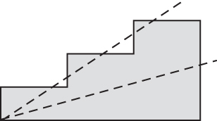
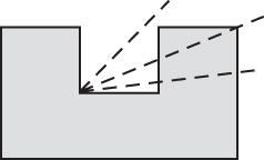
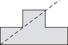
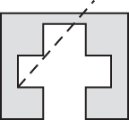
Note that if an obstacle edge coincides with the ray during the calculation process, the λ value needs to be adjusted and rejudged.
Step 2: Connectivity matrix calculation without considering obstacle boundaries.
- a.
At least one node of edge Elk is on an obstacle node, that is, or , where i = 1, ⋯, N, j = 1, ⋯, mi.
- b.
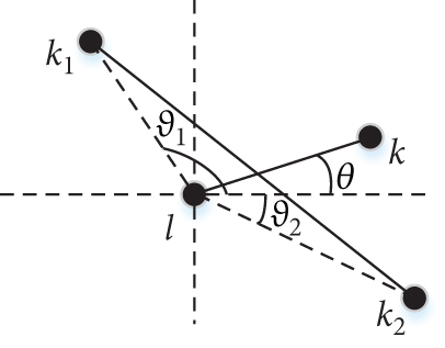
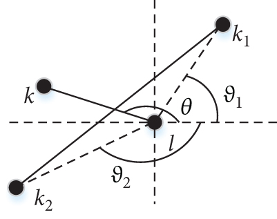
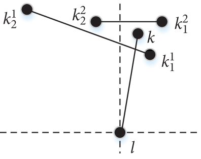
The polar angle θlk of edge Elk is between the two polar angles and corresponding to the two nodes of the obstacle edge. This is divided into two cases: one is when , as shown in Figure 2(a), in which case it is required that . The other case is when , as shown in Figure 2(b), in which case it is required that or ; for obstacle edges that meet the above requirements, select the maximum of the two polar radii corresponding to these obstacle edge nodes to form a set, and then it is required that the polar radius rlk of edge Elk is not less than the minimum value in this set, that is, , as shown in Equation (3), where i, j are the corresponding values of the obstacle edge that meets the polar angle requirements.

Step 3: Connectivity matrix calculation considering obstacle boundaries.
For nonobstacle corner point nodes, such as starting points (or endpoints), since there are no boundaries inside or outside the obstacle, the parts of the connectivity matrix related to these nodes remain unchanged, as calculated in Step 2. However, for nodes that are obstacle corner points, further processing of the nodes related to the connectivity matrix is needed based on their boundaries inside and outside the obstacle. Analyze the connectivity of node l on the obstacle with other nodes. According to Step 1, the polar angle range of the obstacle relative to this node is known. Based on Step 2, all nodes k1, ⋯, ks that are connected to this node are obtained. If the polar angle of node kt relative to node l is within the aforementioned polar angle range, then set ; otherwise, keep it unchanged, where t = 1, ⋯, s.
Step 4: Calculate the shortest path.
By following the above steps, you can obtain the connectivity matrix with a relatively small computational effort, which then leads to the adjacency matrix . Using the Dijkstra algorithm, you can find the shortest paths between all pairs of points, which will necessarily include the shortest path between the starting point P1 and the endpoint P2. Another advantage of using the Dijkstra algorithm is that it reduces the time complexity of subsequent calculations. When the coordinates of the starting point and endpoint change while the obstacles on the map remain the same, subsequent calculations can fully utilize the relevant information between obstacle nodes from the previous computation, thereby reducing the computational effort and saving computation time.
2.2. Linear Fitting of Circular, Elliptical, and Irregular Obstacle Edges
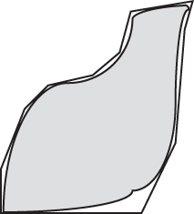
Irregular obstacles, such as circular and elliptical obstacles, contain continuous curves that make direct processing more difficult. A simple approach is to perform edge linear fitting, which includes the obstacle and minimizes the area of nonobstacle regions, thus generating corner points, as shown in Figure 3. Generally, increasing the number of fitting edges can approximate the size of the original obstacle as closely as possible, but an increase in the number of edges will inevitably lead to an increase in the number of corner points, increasing the computational load for path planning. When dealing with such obstacles, when the obstacle size is small, the number of fitting edges can be appropriately reduced to lower the computational load; when the obstacle size is large, the number of fitting edges can be appropriately increased to optimize the computational results.
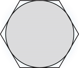
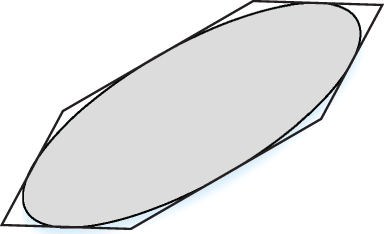
Note that the practice of approximating circular or elliptical obstacles with regular polygons actually lacks a rigorous scientific basis and is not unique. This approach is taken to facilitate batch computation. Theoretically, as the number of fitting edges increases, the shortest path will more closely approximate the theoretical shortest path. However, this also leads to an increase in the number of corners, which reduces edge length, which is not conducive to subsequent path smoothing. Therefore, it is recommended that the number of fitting edges should not be less than 6, and the edge length should be greater than the turning radius during smoothing to facilitate subsequent smoothing processes. In some extreme cases, the fitting polygon can be manually adjusted according to the situation to achieve path smoothing.
For irregular obstacles, as shown in Figure 3(c), manual extraction of the endpoints of the fitting lines is required.
When all circular, elliptical, and irregular obstacles on the map are edge-fitted into polygonal obstacles, you can then construct the corresponding adjacency matrix based on the corner point information of the polygonal obstacles and use the Dijkstra algorithm to obtain the optimal path.
3. Trajectory Smoothing Analysis
Due to the difficulty in analyzing constraints such as obstacles and turning radii with theoretical curves like Bezier curves and B-spline curves, the trajectory’s corner points are processed by smoothing the sampling of the smallest radius arc that can be accommodated at these points and then analyzing whether these arcs intersect with other obstacle edges.
3.1. Arc Treatment of Trajectory Corner Points
The results and discussion may be presented separately or in one combined section and optionally divided into headed subsections.
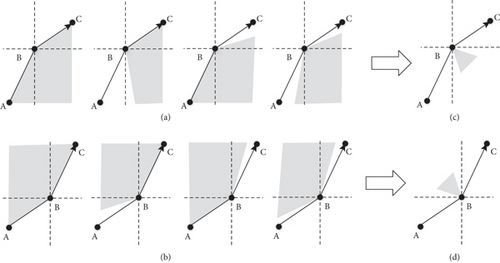
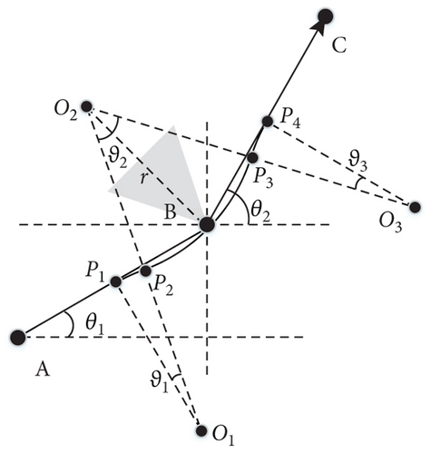
Assuming that a corner point of the trajectory consists of two edges, AB and BC, with the direction from A → B → C, there are two possible relationships between the trajectory direction at corner point B and the obstacle: Situation 1, where the obstacle is on the right side of the trajectory direction, as shown in the four cases of Figure 4(a), which represent the trajectory occupying two edges, one edge, or a corner point of the obstacle. For unified expression, these are represented in Figure 4(c): Situation 2, where the obstacle is on the left side of the trajectory direction, as shown in the four cases of Figure 4(b), which represent the trajectory occupying two edges, one edge, or a corner point of the obstacle. Unified expressions are represented in Figure 4(d).
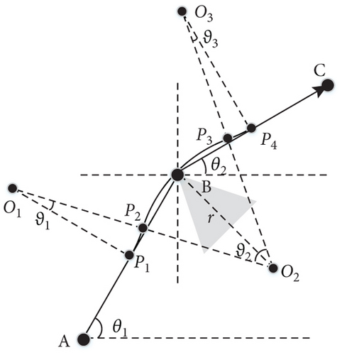
| Parameters | Value |
|---|---|
| O1 | |
| O2 | (xB − ℓABC · rsin((θ1 + θ2)/2), yB + ℓABC · rcos((θ1 + θ2)/2)) |
| O3 | |
| P1 | |
| P2 | (O1 + O2)/2 |
| P3 | (O3 + O2)/2 |
| P4 | |
| ϑ1, ϑ3 | arccos((1 + |cos(θ1 − θ2)/2|)/2) |
| ϑ2 |
When the distance dAB or dBC between AB or BC is less than 5.5 r, it may become impossible to use a three-arc smoothing process. For example, moving from behind a building to the front of the building is relatively easy for a moving carrier, but it becomes very difficult for a high-speed moving aircraft due to the large turning radius of the aircraft. An additional heading segment needs to be considered for analysis to address this phenomenon. Assume the three segments of the flight path are AB, BC, and CD, with the direction from A → B → C → D, and the distance BC is short.
First, analyze the situation when the distance dBC between B and C is less than or equal to 2r. Draw a circle passing through points B and C with a radius of r, and the center of the circle is on the axis of BC and the side of the obstacle. Draw tangents BB’ and CC’ from points B and C to the circle, as shown in Figure 6. If the route is located between the center of the circle and the tangent, it is called the inside, and otherwise, it is called the outside. The first segment AB is called the entry, and the last segment CD is called the exit, so there are four situations in total. The first situation is inside–inside, as shown in Figure 6(a), where the smoothed arc is divided into three segments, all with a radius of r. The first arc has its center at O1, the second arc has its center at O2, and the third arc has its center at O3. The second situation is inside–outside, as shown in Figure 6(b), where the smoothed arc is divided into four segments. The first arc has its center at O1, with a radius of r, the second arc has its center at O2, with a radius of r, the third arc has its center at O3, with a radius of r3, and the fourth arc has its center at O4, with a radius of r. O3 is located on the line O3B, and r3 > r. If r3 is too large, it will increase the distance between P4 and C, and the deviation from the flight path will also increase, making it easy to intersect with other obstacle edges. It is recommended to set the value between 1.1r and 2r. The third situation is outside–inside, as shown in Figure 6(c), similar to the second situation, but with the direction reversed. The smoothed arc is divided into four segments. The first arc has its center at O1, with a radius of r, the second arc has its center at O2, with a radius of r2, r2 > r, the third arc has its center at O3, with a radius of r, and the fourth arc has its center at O4, with a radius of r. The fourth situation is outside–outside, as shown in Figure 6(d), where the smoothed curve no longer passes through points B and C. The arc is divided into three segments. The first arc has its center at O1, with a radius of r, the second arc has its center at O2, with a radius of r2, and the third arc has its center at O4, with a radius of r, where r2 > r, and O2 is located on the axis of BC.
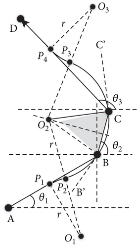
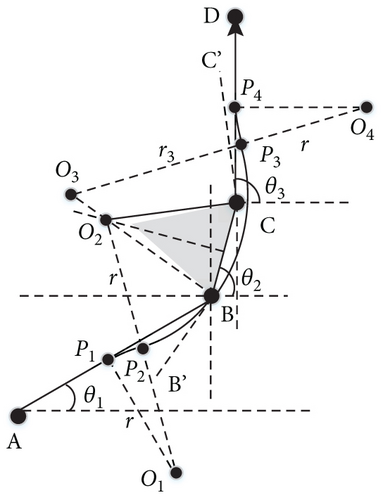
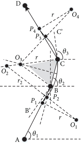
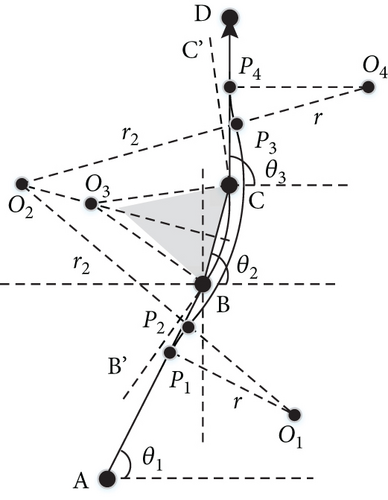
Secondly, define , which represents the threshold distance for the BC segment that allows the three segments of the flight path A → B → C → D to be decomposed into AB → BC and BC → CD for processing. When the distance between BC satisfies , for this situation, you can refer to the four cases in Figure 6, with the difference being that the radius r of the arc increases to more than 1/2 the distance from BC. If you want the smoothed curve to be as close to the flight path as possible, you can replace r with , the corresponding r2, r3 should be greater than this value, and it should also be greater than the shortest distance from the corresponding center to the CD line. When the distance between BC satisfies , it is directly decomposed into AB → BC and BC → CD segments for separate processing. If AB is at the beginning, then , and if CD is at the end, then .
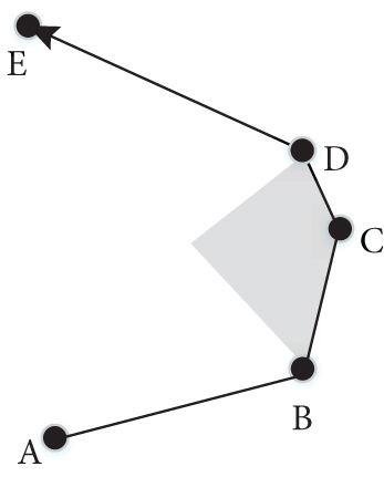
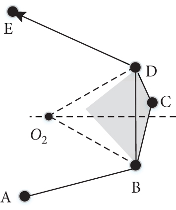
For cases involving multiple consecutive shorter flight paths, such as A → B → C → D → E, where BC and CD are short distances, as shown in Figure 7(a), they can be transformed into the form A → B → D → E, as shown in Figure 7(b), and then processed, as shown in Figure 6. If it is difficult to meet the requirements, you can solve it by appropriately increasing the radius r, while also paying attention to the possibility of conflicts with other obstacle edges as the radius increases. If the radius cannot be adjusted to meet the requirements, the path should be abandoned, and the next best path should be analyzed. If all feasible paths cannot meet the requirements, some obstacles can be “reduced edge and expanded domain” (for example, changing a circular obstacle from a previous hexagon to a square or expanding a hexagonal obstacle into a rectangle) and then resolve the flight path and perform smoothing processing. If this cannot find a path that can be smoothed, the problem is considered unsolvable. A typical example is a fighter jet flying close to the ground on city streets, where the jet’s turning radius is too large, and no matter how the flight path is chosen, the jet cannot complete the turn operation.
3.2. Obstacle Avoidance Analysis of Smoothed Path
A path composed of straight lines will not collide with obstacles, but the arcs resulting from smoothing may intersect with obstacle edges (these obstacle edges are not associated with the arc in question). There are three possibilities for the arc and each obstacle edge: no intersection, one or two intersection points. The one intersection point can be further divided into tangential and intersecting. Tangential means the arc is passable, while intersecting means the arc is not passable. The shortest distance between the arc’s center and the obstacle edge can be used to distinguish between these cases; if the shortest distance is equal to the arc’s radius, it is tangential, and if it is less than the radius, it is intersecting. For each arc segment, the following information is recorded: {idarc, O, r, [θstart, θend], sgnccwise, sgn{A, B, C}}, where idarc is the arc identifier, O is the position of the arc’s center, r is the arc’s radius, [θstart, θend] represents the starting angle and ending angle of the arc, sgnccwise is the counterclockwise sign, with sgnccwise = 1 indicating that θstart rotates counterclockwise to θend, and sgnccwise = 0 indicating a clockwise direction, {A, B, C} indicates that this arc segment belongs to the path A → B → C. If the arc intersects with any obstacle edge (these obstacle edges do not belong to AB or BC), then sgn{A, B, C} = 0, indicating that the path A → B → C is not passable. Only when all sgn{A, B, C} for the arcs in the A → B → C path are 1, it is indicated that the path A → B → C is passable; similarly, if it is {A, B, C, D}, it indicates that it belongs to the path A → B → C → D, and the analysis process is the same. A complete path has only one allocation method; for example, the path A → B → C → D → E → F, based on the length of each segment, is ultimately divided into three segments of A → B → C, B → C → D, and C → D → E → F, and then the arc situations corresponding to each segment of the path are analyzed. If all arcs do not intersect with obstacle edges, it is considered that the path can be passed.
There are two ways to obtain the final smoothed path.
The first method is the path analysis method, which proceeds as follows:
Step 1: Initialize and process the map data, including handling circular, elliptical, and irregular obstacles.
Step 2: Read the map data, starting from the starting point, and use a greedy algorithm strategy to traverse to the nearest unvisited neighboring node at each step, expanding until reaching the endpoint to find the optimal path. The difference is that nonoptimal paths are also saved, sorted by distance from smallest to largest, and these paths and distances are saved in a set.
Step 3: Smooth the optimal path. If it cannot be smoothed, proceed to Step 5. If it can be smoothed, move to the next step.
Step 4: Determine if each smoothed arc intersects with any obstacle edge. If there is an intersection, proceed to Step 5. If no intersections exist, save the path, shortest distance, and exit.
Step 5: Remove the current optimal path from the set if it cannot be smoothed. If the set is not empty, read the optimal path from the set and go back to Step 3. If the set is empty, proceed to the next step.
Step 6: Perform “edge reduction and domain expansion” on some obstacles. First, the number of edges of circular, elliptical, and irregular obstacles should be reduced. For example, change the number of edges of a circular obstacle from 8 to 6, down to 4, selecting objects from smaller to larger; second, expand some linear obstacles to become four-sided after expanding the area, again selecting objects from smaller to larger; after modifying the map, go back to Step 2. If no smoothing solution is found after these operations, exit and give a no solution prompt.
The second method is the path condition search analysis method, which proceeds as follows:
Step 1: Start by initializing and processing the map data, which involves dealing with circular, elliptical, and irregular obstacles and creating a set of paths that cannot be processed.
Step 2: Read the map data and start from the starting point. Use a strategy based on the greedy algorithm to traverse to the nearest unvisited neighboring node at each step, expanding the search until reaching the endpoint to find the optimal path. The main difference is that when encountering a path that is part of the unprocessable path set, the corresponding next node must be excluded. For example, if there is an unprocessable path set containing a path A → B → C, when the search reaches node B and the previous node is node A, the next node will be skipped (in this case, node C). If a feasible solution cannot be found, proceed to Step 5. If a feasible solution exists, move on to the next step.
Step 3: Smooth the optimal path. If it cannot be smoothed, for example, if AB and BC are both less than their threshold distances, add the flight path A → B → C to the unprocessable path set and proceed to Step 5. If it can be smoothed, move to the next step.
Step 4: Determine if each smoothed arc intersects with any obstacle edge. If no intersections exist, save the path, shortest distance, and exit. If there is an intersection, for example, if the arc of the flight path A → B → C intersects with some obstacle edge, add the flight path A → B → C to the unprocessable path set and proceed to Step 2.
Step 5: Clear the unprocessable path set and perform “edge reduction and domain expansion” on some obstacles. First, the number of edges of circular, elliptical, and irregular obstacles should be reduced. For example, change the number of edges of a circular obstacle from 8 to 6, down to 4, selecting objects from smaller to larger; second, expand some linear obstacles to become four-sided after expanding the area, selecting objects again from smaller to larger; after modifying the map, go back to Step 2. If no smoothing solution is found after these operations, exit and give a no solution prompt.
4. Path Planning and Smoothing Analysis After Expansion
4.1. Expansion Radius Analysis
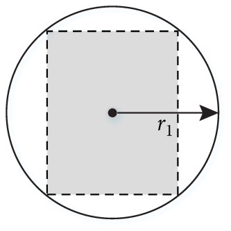
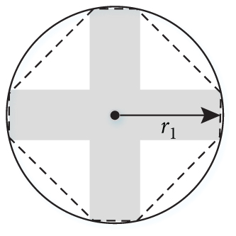
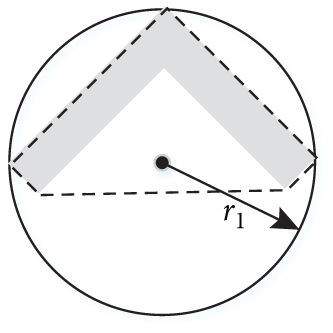
where S represents the area enclosed by the protruding vertices of the obstacle, which is the area surrounded by the dashed line in Figure 8. The larger S is, the better the approximation effect, and a threshold value can be set. If η is greater than this threshold, it is considered that the route obtained after the expansion is optimal. If it is lower than the threshold, it is considered that the route obtained after expansion is not optimal. This method can filter out slender mobile carriers like subway cars, as their analysis process is more complex.
In addition, since there may be deviations when the mobile carrier follows the route, this maximum deviation distance is denoted as r2. Therefore, the safe distance r0 between the center of the mobile carrier’s circular approximation and the obstacle’s edge is r0 = r1 + r2. For ease of analysis, the mobile carrier is treated as a point mass at the center, and the obstacle is expanded according to r0.
The expansion process brings about two changes. First, some independently existing obstacles may overlap, and in this case, the two obstacles need to be merged into one for processing, and the edges and nodes of the obstacle need to be recalculated. Second, some corners of the straight lines will become arcs. The presence of arcs introduces new characteristics to path planning and smoothing.
4.2. Path Planning Algorithm After Expansion
For the fusion processing required due to overlaps between obstacles, since it involves many arcs, it is possible to manually linearize and fit the overlapping arc sections of the region. There are four main possibilities after expansion for obstacle corner points composed of straight lines that do not overlap. If the angle of the obstacle node is less than π, as shown in Figures 9(a), 9(b), and 9(c), an angle point expands into two corner points connected by an arc with a radius of r0; if the angle of the obstacle node is greater than π, as shown in Figure 9(d), the expansion still results in only one point, but due to its nonconvex nature, it will be ignored during the process of finding the optimal path. For the smoothing of the flight path A’ → B’ → B” → C’, if the minimum turning radius r of the mobile carrier is less than or equal to r0, the flight path remains unchanged if r > r0, and smoothing is carried out according to Figure 9(d), where the center O2 is on the angle bisector of ∠ABC and is inscribed in .
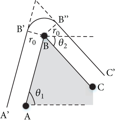
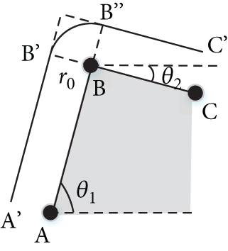
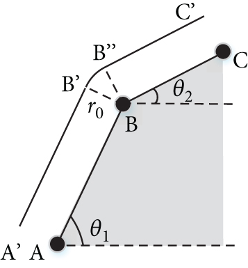
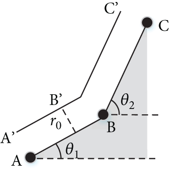
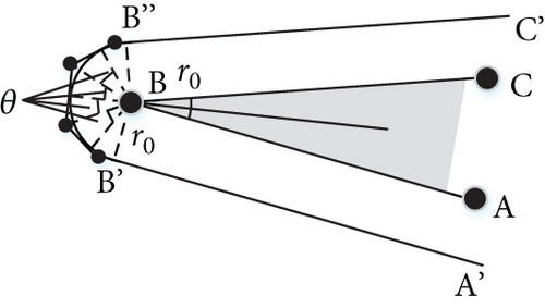
However, in actual path planning, the path does not strictly follow the edges of the obstacles. The above method is no longer applicable when the path moves from one obstacle to another. Therefore, the aforementioned arc linearization method is still used, as shown in Figure 10, where a tangent to the arc is made along the angle bisector of obstacle corner point B and expanded outward according to angle θ until it intersects with A’B” and B”C’. If θ is set to π/3, then when ∠B′BB" > 2/3π, the arc can be divided into 5 segments, as shown in Figure 10(a); when 0 < ∠B′BB" ≤ 2/3π, the arc can be divided into 3 segments, as shown in Figure 10(b). After processing all obstacle corner points in this manner, path planning is conducted based on the search for obstacle corner points.

4.3. Path Planning and Smoothing Algorithm After Expansion
After the obstacles are expanded, the optimal path is obtained by linearizing the arcs based on the search for obstacle corner points. After obtaining the final path, linearization processing is applied to the optimal path. The process flow for path planning and smoothing after expansion is as follows:
Step 1: Perform expansion processing on the obstacles in the map, then linearize the obstacle curves, including the arcs generated after expansion, and update the obstacle data.
Step 2: Read the map data, starting from the starting point, traverse to the nearest unvisited neighboring nodes of the starting point until the endpoint is reached to find the optimal path. The difference is that nonoptimal paths and results are also saved, sorted by distance from smallest to largest, and these paths and distances are saved in a set.
Step 3: Smooth the optimal path. If it cannot be smoothed, go to Step 5. If it can be smoothed, proceed to the next step.
Step 4: Determine if each smoothed arc intersects with any obstacle edge. If there is an intersection, proceed to Step 5. If no intersections exist, save the path and shortest distance and exit.
Step 5: Remove the current optimal path from the set if it cannot be smoothed. If the set is not empty, read the optimal path from the set and go back to Step 3. If the set is empty, proceed to the next step.
Step 6: Perform “edge reduction and domain expansion” processing on some obstacles. First, the number of edges of circular, elliptical, and irregular obstacles should be reduced. For example, change the number of edges of a circular obstacle from 8 to 6, down to 4, selecting objects from smaller to larger; second, expand some linear obstacles to become four-sided after expanding the area, selecting objects again from smaller to larger; after modifying the map, go back to Step 2. If no smoothing solution is found after these operations, exit and give a no solution prompt.
5. Results
To substantiate the aforementioned research, we employed MATLAB as our simulation verification platform. We implemented the aforementioned algorithms, loaded the predefined map data, invoked the corresponding algorithms, and presented the results visually, thereby confirming their efficacy.
5.1. Corner-Point-Based Route Planning
Figure 11 is an example of finding the shortest path in a maze based on polygonal obstacle corners. The two red dots represent the starting and end points, respectively, and the maze consists of two obstacles with 132 and 162 corner points each. The blue lines are the edges formed by all connectable nodes, and to prevent the shortest path from passing outside the maze, the connectable edges outside the maze are removed. The green lines represent the shortest path found using the Dijkstra algorithm based on these connectable edges. Compared to grid algorithms like A∗, the Dijkstra algorithm based on polygonal obstacle corners yields the shortest path, although it takes longer to compute. If the width of the maze corridors is taken as a unit length, then the shortest length of the maze searched based on obstacle corner points is 110.3, while the shortest length of the route planned using A∗ or Voronoi diagram is calculated to be 133. This indicates that even within the confines of a narrow maze, the shortest path searched based on obstacle corner points has a significant length advantage.

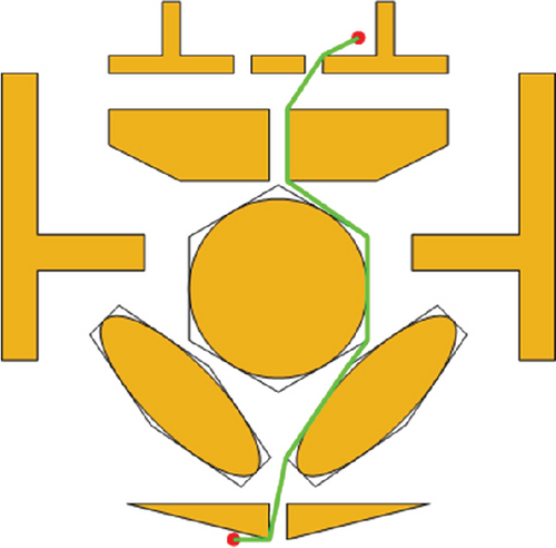
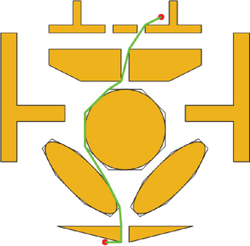
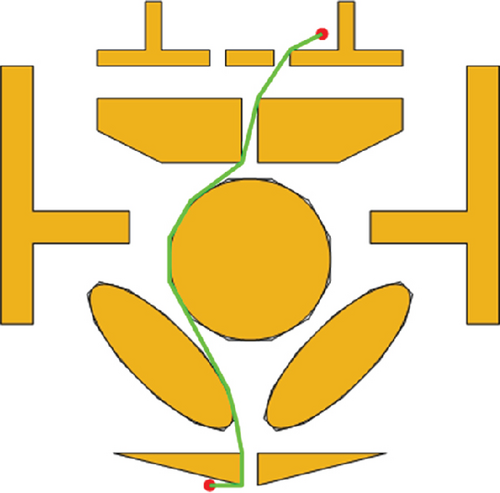
Figure 12 is an example of finding the shortest path by edge-fitting circular and elliptical obstacles into polygons, specifically hexagons, octagons, and dodecagons. The figure shows that as the number of fitting sides increases, the area of the polygon approximated by straight lines gets closer to the original shape, and the found shortest path also gets closer to the theoretically shortest path.
5.2. Route Smoothing
Smoothing the trajectory with two-line segments for the route shown in Figure 11, as depicted in Figure 13(a). There are seven unreasonable points in the figure, two of which are shown in Figure 13(b), indicating a reversal phenomenon on the route. The unreasonable points are smoothed with three or more line segments, as shown in Figure 13(c), which eliminates the reversal issue on the route. The red dots in the figure correspond to the operation of a segment of the arc, and the blue dots correspond to the starting and ending points of the arc.
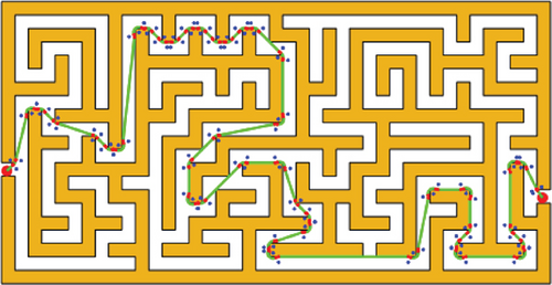
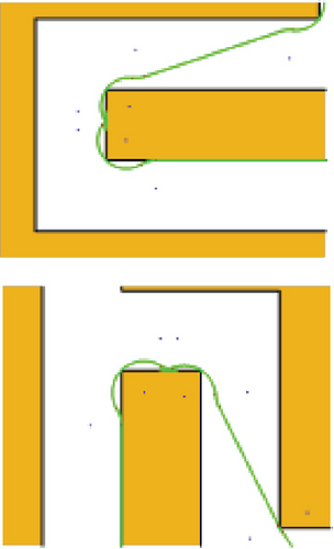
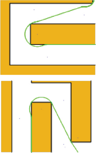
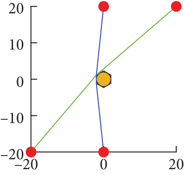
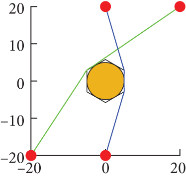
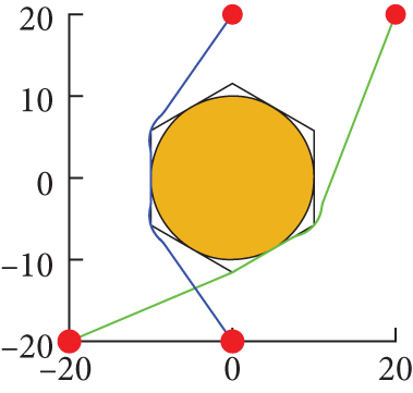
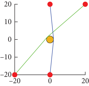
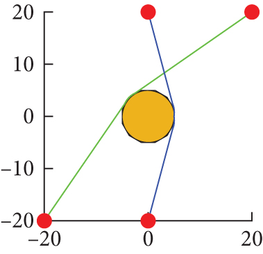
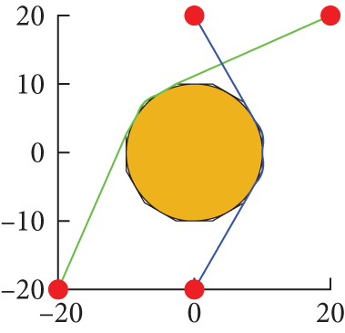
Figure 14 shows the smoothed flight path curves for circular obstacles with a minimum turning radius of 4 and different sizes. From top to bottom, the top three figures show circular obstacles inscribed in a hexagon, and the bottom three figures show circular obstacles inscribed in a dodecagon; from left to right, the left two figures have circular obstacles with a radius of 2, the middle two figures have circular obstacles with a radius of 5, and the right two figures have circular obstacles with a radius of 10. From the figures, it can be seen that even when there is a certain gap between the minimum turning radius and the size of the obstacles on the flight path, the smoothing algorithm still has good adaptability.
5.3. Smoothing of Routes After Obstacle Expansion
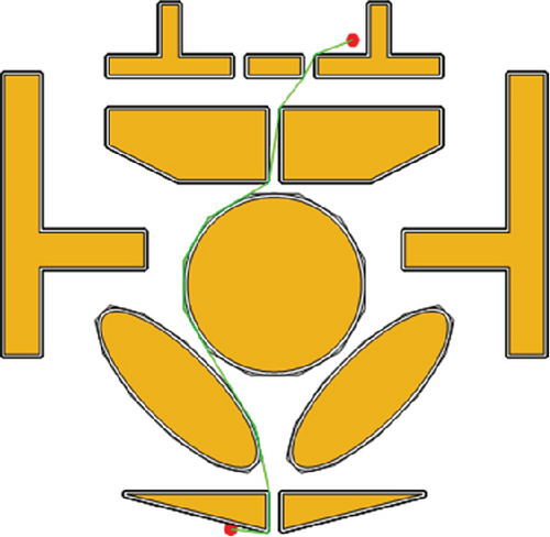
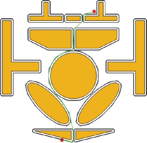
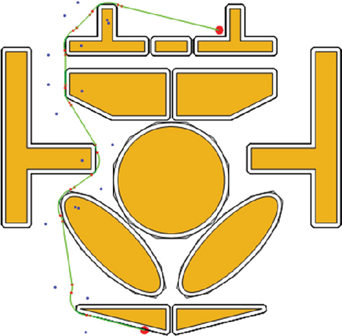
The expansion of obstacles in Figure 12, using a dodecagon to fit the circular and elliptical obstacles in the figure, has been studied for optimal smooth paths under different expansion radii and minimum turning radii. Figures 15(a) and 15(b) show that when the turning radius is small, the smoothed path can basically follow the shortest path forward; Figure 15(b) also indicates that even when the expanded channel is extremely narrow, with the narrowest point being only 1, as long as the minimum turning radius is small enough, the smoothed flight path can still be the shortest path; Figure 15(c) has a minimum turning radius of 10, at which point the shortest path cannot be smoothed, and many reachable flight paths also face the same problem. After repeated iterations, a reachable and smooth path is finally selected, with the blue dots in the figure representing the circular part of the smoothed arc and the red dots representing the boundary of the arc. This shows that as the turning radius increases, the difficulty of finding the optimal smooth flight path in the presence of obstacles increases. Once a path that can basically meet the smoothing requirements is determined, further optimization of the path can be carried out, such as changing the position and radius of the arc center. Generally speaking, as the turning radius increases, a larger clearance area is needed, and the straight-line distance of the flight path must be longer to ensure that the smooth flight path can fall on the straight line.
6. Conclusions
The article conducts research based on a two-dimensional plane, and compared to the optimal path obtained from the Voronoi diagram, it is easier to search the smoothed paths that cannot be detected by the Voronoi diagram under the premise of guaranteeing safety because the shortest path planning leaves more space for smoothing. At the same time, by introducing the concept of safety radius, the issue of imprecise path tracking during the movement of the mobile carrier is effectively avoided, ensuring a certain level of safety. This has significant implications for planning under extreme conditions. For three-dimensional map environments that can be compressed into two dimensions, such as urban streets and buildings, the variations in height can be disregarded. Instead, a slice of a height layer can be presented on a two-dimensional plane through an orthographic projection. After the overlap of buildings, the remaining part serves as a traversable area. Path planning research can then be conducted within this height layer, reducing the complexity of path planning in three-dimensional space to a certain extent. When the map information is unknown and requires search, the location information of obstacle point clouds in the environment can be obtained through laser or binocular SLAM methods. These point clouds can be converted into obstacle contours for the explored areas through clustering separation and other computational methods. As for the unexplored areas, they are all considered obstacle areas. Even if not all areas have been explored, planning research can be carried out within the searched areas. This approach can also be extended to dynamic route optimization in the case of moving obstacles by continuously updating the map and route in real-time to find the optimal route.
This paper focuses on finding the shortest traversable path in a two-dimensional environment and smoothing the path to meet the turning curvature constraints of the moving carrier while avoiding secondary obstacle avoidance during the smoothing process. The search is repeated iteratively until a smooth route that meets the requirements is found. The study’s limitations are that conclusions about unsolvable path planning in a certain environment may not be reliable, as some feasible solutions might be missed due to the limitations of the processing method. Another limitation is that introducing arcs means that the optimal route may not necessarily be globally optimal.
Disclosure
The work was conducted as part of the employment of the authors at the Naval Aeronautical and Astronautical University.
Conflicts of Interest
The authors declare no conflicts of interest.
Author Contributions
Lingsong Di designed and conducted the experiment and wrote the manuscript. Defeng Sun completed the derivation of the formula to verify. Yahui Qi and Zhicai Xiao supervised whole project.
Funding
The authors received no specific funding for this work.
Acknowledgments
The authors would like to express their gratitude for the insights and contributions found in the preprint titled “Research on Path Planning and Smoothing Based on Obstacle Corner Points,” which is accessible at https://www.researchsquare.com/article/rs-3870219/v1.
Open Research
Data Availability Statement
Related documentation, code, and images are available at https://gitee.com/dilingsong/shortest-path-planning-and-smoothing/tree/master/.


