Suspension Conversion Technology of New-Generation Manned Spacecraft
Abstract
The new-generation manned spacecraft employs a new recovery system of parachutes and airbags. In order to realize the effective cushion of the return capsule airbag, the conversion of the single-point hanging to the double points for the spacecraft is necessary. In the conversion process, the long hanging rope and the height of the return capsule will cause a large impact and disturbance to the cabin, but the traditional dynamic modeling method is not suitable for those with complex boundary conditions. In order to solve these problems, a finite element model is proposed to analyze the suspension conversion process and simplify the parachute model based on the aerodynamic load dynamic matching control method to analyze the dynamic response characteristics, such as overload, speed, and force of the cabin, quantifying the conditions of the rope in the process. Results are generally consistent with experimental data. This study provides guidance for future optimization work and will greatly support the safe-return technology of the new-generation manned spacecraft.
1. Introduction
China’s new-generation manned spacecraft has a return cabin with a new aerodynamic shape, which fully takes into account multiple tasks such as low-Earth orbit autonomous flight, space station operation, and manned deep space exploration. The goal is to achieve personnel commuting and cargo transportation. Compared with the current Shenzhou spacecraft [1], the new-generation manned spacecraft has greater transportation capabilities and adapts to multiple return modes near the ground and deep space. Its recovered weight is heavier than 7500 kg and can be reused, as shown in Figure 1. It is shown that the spacecraft adopts a group parachute system for pneumatic deceleration and large-load airbag cushioning to realize the safe and nondestructive recovery of the return cabin.
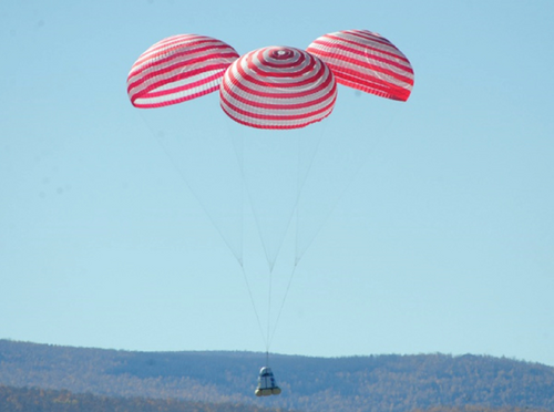
Different from the single-point hanging mode of the spacecraft landing on the sea, the new ship needs a two-point hanging mode to adopt cushion airbags for soft landing. In the process of converting from single-point hanging to double-point mode, the rope tears the thermal protection layer and pulls it out from the cabin’s groove. The nonlinear relationship between them is complicated. This process seriously affects the motions of the cabin, like overload and disordered rolling. It also affects the subsequent working procedures, especially the damping characteristics. Complicated processes such as the free fall of the cabin and the secondary inflation of the parachute have a great impact on the attitude of the cabin and the experience of astronauts in the future. In fact, research on the motion and interaction of spacecraft and their parachute has been carried out worldwide [1–5]. Typical manned spacecrafts at home and abroad are shown in Table 1. The landing methods are different at different landing areas, and the modes of conversion suspension are also different.
| Item | Apollo (United States) | Soyuz (Russia) | Shenzhou (China) | Orion (United States) | Dragon (United States) | CXX-100 (United States) | PPTS (Russia) | New-generation spacecraft (China) |
|---|---|---|---|---|---|---|---|---|
| Configuration |  |
 |
 |
 |
 |
 |
 |
 |
| Landing mode | Water area (direct enter) | Land (thrust reverser) | Land (thrust reverser) | Water area (direct enter) | Water area (direct enter) | Water area/land (airbag cushion) | Land (buffer bracket) | Water area/land (airbag cushion) |
| Need suspension conversion (yes/no) | No | Yes | Yes | No | No | Yes | No | Yes |
For spacecraft systems landing on the water, such as the US Apollo [6], Orion [7], and Dragon [8] spacecraft, this type of spacecraft generally uses the single-point hanging mode to land on the water, and the hanging return cabin is in an offset state. When entering the water, the cabin gradually enters the water along an entry angle, which can greatly reduce the landing impact. This mode does not require a suspended conversion process [9].
For spacecraft systems landing, cushion airbags and cushion engines are generally used, such as Russia’s Soyuz, the American CXX-100, China’s Shenzhou, and the new-generation manned spacecraft. In principle, the axis of the return cabin of this type of spacecraft needs to be perpendicular to the ground when landing, which requires at least two-point hanging. In traditional spacecraft, single-point hanging is generally used when decelerating at high speed. To the new-generation manned spacecraft, it requires the conversion from a single-point to a double-point suspension [10–13].
Other spacecrafts such as the American CXX-100 adopt a rigid structure conversion. When converting from a single point to a double point, it uses a rigid structure similar to the “kettle handle.” This structure rotates around a rotating shaft, and a damper is configured in the process of reducing the conversion overload, and the process is slow, orderly, and controllable. Russia’s PPTS spacecraft uses a landing reverse thrust engine with a landing buffer support for landing, which does not involve the problem of hangover.
In summary, Russia’s Soyuz, China’s Shenzhou, and the new-generation manned spacecraft all involve the use of ropes to convert from single-point hanging to double-point hanging, and this process needs to be analyzed. Many researchers have conducted in-depth analysis of the conversion process of the return capsule. For example, Song et al. of the National University of Defense Technology have established a dynamic model of the parachute system with an inverted “Y” type suspension for a certain type of spacecraft, considering rigid body dynamic equations with the additional mass and modeling method of suspension system based on the assumption of “balance point.” The model is used to simulate and analyze the airdrop test of the spacecraft, and the model is verified by the test data [14, 15]. Wang et al. propose a finite element analysis method to establish a dynamic analysis model for the main parachute out of the cabin to solve the aforementioned problem and accurately understand the changes produced in this process [16]. Wang et al. focus on the effect of attack angle on the ejection and deployment of a parachute. Based on the overset grid technology, the three-dimensional unsteady Reynolds averaged Navier–Stokes (URANS) coupled with a six-degrees-of-freedom (6DoF) equation of motion is applied to the research [17]. Wang established the multibody dynamic model of the deployment process of a large parachute and adopted the mass-spring-damper model to simulate the suspension line and canopy [18]. In the paper, the flight dynamic model of the parachute system is proposed for the whole deplaning airborne process, including parachute deployment, inflation, and the steady descent stages [19].
However, all related studies use simplified dynamic models. The description of the process of pulling off the heat-proof block of the rope generally uses a constant value. Actually, the pulling force is a step load. Besides, the force direction during the pulling-off process is also constantly changing. Accordingly, the traditional dynamic analysis method is not accurate enough to describe the entire process of pulling off the heat shield, converting, and hanging. We propose a finite element method to establish a numerical model for the conversion of the return cabin from a single-point hanging state to a double-point hanging state and provide a new solution for the description of the process.
2. Design of Spacecraft Return Module
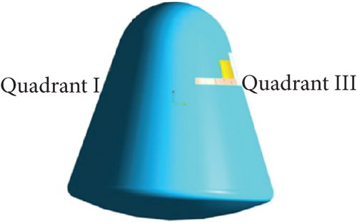
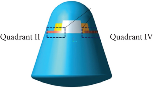
We divide the space around the spacecraft into four quadrants to show position relationships, which can be seen in Figures 2(a) and 2(b). In the initial state (shown in Figure 2(c)), the return cabin is in a single-point hanging state, and the hanging point is in the third quadrant. At this time, the line connecting the hanging point and the center of mass is perpendicular to the ground. When the suspension conversion starts, two 4-m-long ropes (which begin to converge in the third quadrant position) are used to pull off the heat protection layer, and finally, the two ropes are connected to the II and IV quadrant positions, respectively. The status after the conversion suspension is shown in Figure 2(d).
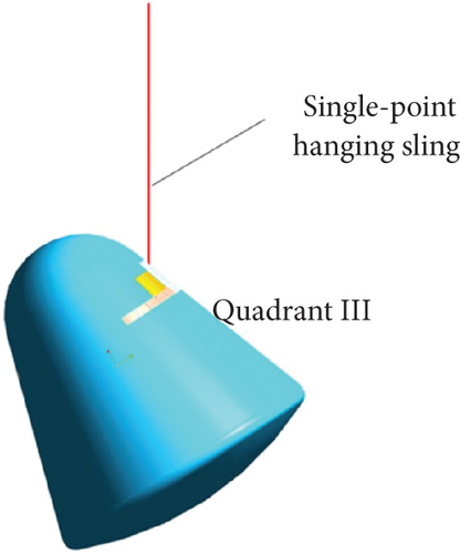
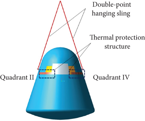
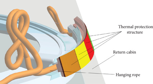
During the conversion process, the cable tears the heat-proof structure and pulls it out from the groove of the thermal protection layer. The nonlinear relationship between them is complicated. This process seriously affects the motion of the cabin and causes the attitude fluctuation of the return cabin, which will seriously affect the subsequent landing buffer procedures, especially the subsequent damping. And it directly affects the overload characteristics of the entire cabin. In order to analyze the influence of the pull-off force of the thermal protection structure embedded in the side wall on the whole return cabin, the pull-off force is set at 5~20 kN. Figure 3 shows the relationship between the hanging rope and the heat-proof structure. The hanging rope lifts the heat-proof structure and destroys it during the conversion process.
The material properties of each part of the return capsule can be seen in Table 2.
| Part name | Parameter | ||
|---|---|---|---|
| Density (kg/m3) | Elastic modulus (GPa) | Poisson’s ratio | |
| Sling | 805 | 13.1 | 0.3 |
| Canopy | 1400 | 10 | 0.3 |
| Heat shield | 2700 | 1 | 0.3 |
| Connecting bands | 805 | 6.4 | 0.3 |
| Suspension lines | 300 | 2.9 | 0.3 |
3. Finite Element Modeling of Return Cabin
To accurately describe the dynamic characteristics of the suspension conversion process of the return cabin, the whole model was established in Abaqus 6.14. The canopy aerodynamic force is applied to realize its real-time control, and the dynamic responses with various parameters during the suspension conversion process of the return cabin are analyzed.
Μ is the generalized mass matrix and Φ is the constraint equation, where , , and q are the generalized node coordinate vectors, generalized velocity, and acceleration vectors, respectively. Φ is the constrained Jacobian equation and λ is the Lagrange multiplier, where F and G are the generalized elastic force and the generalized external force vectors, respectively.
3.1. Geometrical Model
As shown in Figure 4, a full-scale geometric model of the suspension conversion of the return cabin including three main parachutes is established using CATIA.
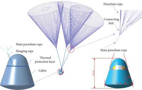
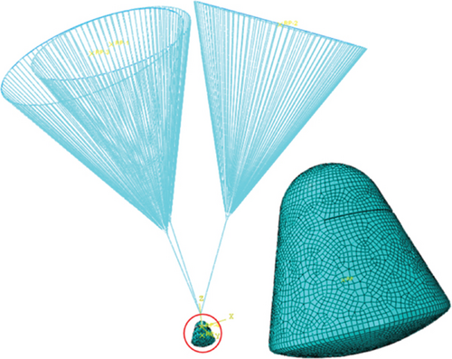
The geometric model is then introduced into Abaqus. The corresponding suspension conversion finite element model is established and shown in Figure 5. The return capsule is carried out with geometric cleaning and meshed with shell elements, and each part is assigned with material properties, respectively. The return cabin body is a surface model, applying rigid constraints with concentrated mass. The parachute ropes, main parachute ropes, and hanging ropes are simplified into one-dimensional elements, that is, truss elements, and only bear tensile forces. The above components are joined by tie connections, and the failure element is used to connect the thermal protection layer and the return cabin to simulate the pull-off force. Finally, the above materials and structures are given corresponding material properties, and initial conditions are given to each component system of the return cabin, including initial velocity and gravitational acceleration. The solver of Abaqus is explicit. The size of the rope mesh is 20 mm, the heat-resistant layer is 10 mm, and the cabin mesh is 60 mm. The total number of the grid is approximately 500,000.
3.2. Aerodynamic Loading Simulation
Figure 6 shows the finite element model under aerodynamic force loading. VUAMP is used to realize the quantification of the force distribution of the system by the deformation of the parachute ropes, connecting belts, and ropes connecting the canopy and the cabin, which more truly reflect the coupled relationship between the aerodynamic force and velocities. And the calculation is more accurate by revising the algorithm. Firstly, the center velocity v and attitude angle n of the parachute are extracted by simulation, then the velocity direction of the parachute is determined, and the aerodynamic force Ff is calculated. Then, whether considering the additional mass is decided based on the acceleration a and the axial direction vector n of the canopy. In the whole process of conversion, the calculation is carried out iteratively to the stable state [20, 21].

4. Results and Discussion
Based on the above simulation method, dynamic response characteristics including overload, velocity, and attitude changes under standard working conditions are analyzed. In addition, the effects of different initial speeds and pull-off forces are discussed, and the load status of each load-bearing part of the return cabin is quantified.
4.1. Standard Working Conditions
The initial speed for the suspension conversion process of the return cabin under standard working conditions is 8 m/s, and the pull-off force of the thermal protection layer is 5 kN. Figure 7 shows the change in the load of the hanging rope along with time during the suspension conversion of the return cabin. The peak force of the rope is 40.6 kN, and the process of pulling the rope off the thermal protection layer lasts about 0.28 s. The load of the rope rose rapidly to a peak, then dropped slightly, and finally remained stable. It can be seen from the load curve of the hanging rope that the forces of the two ropes are relatively uniform, and during the period, the ropes are alternately tensioned.
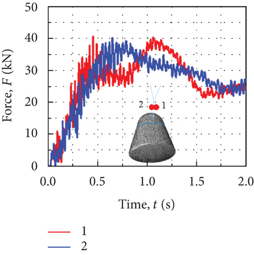
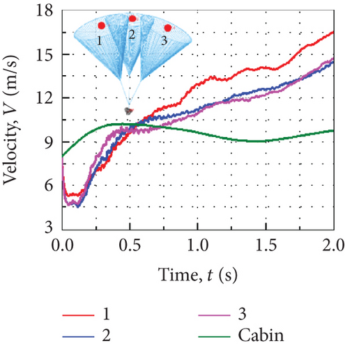
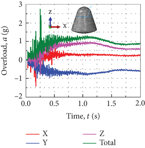
Figure 8(a) shows the velocity curves of the three main parachutes and the reentry module during the suspension conversion process. The initial speeds of the return cabin and the three main parachutes are both 8 m/s. The return cabin gradually accelerates and then decelerates while the three main parachutes decelerate first and then accelerate. Finally, the entire system tends to descend steadily, and the overload of the return cabin stabilizes at about 1 g. Moving with the drop of the parachute cabin, the single main parachute also gets away from the other two. The latter movement always exists during the entire suspension conversion process, so it is considered that they are moving away from each other at an increasing speed, leading to an increase in resultant velocity. Figure 8(b) shows the overload curves during the suspension conversion of the return cabin. The X-direction overload component is small, and the Y-direction and Z-direction are the main contributions. The peak value of the combined overload of the return cabin is about 2.7 g (2.5 g measured in the airdrop test). The simulation and the experimental results are corresponding. The rotation angles of the return cabin around the X- and Y-axis are relatively large, and the one around the Z-axis is small.
4.2. Different Initial Velocities
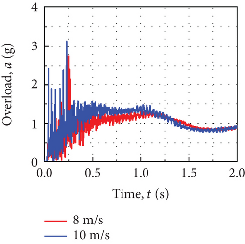
The return cabin adopts three main parachutes to decelerate itself, and the steady vertical descending speed is not more than 8 m/s. When one of the three parachutes fails, the return cabin adopts the other two, and the vertical steady descending speed is not more than 10 m/s. Therefore, two different steady speeds, that is, 8 and 10 m/s, are considered in the process of suspension conversion, and the pull-off force of the fixed thermal protection layer is 5 kN.
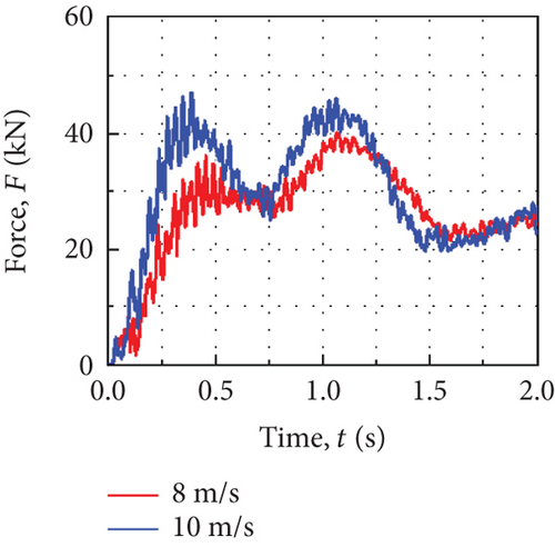
Figure 9(a) shows the change of the rope load with time during the suspension conversion of the return cabin at different initial speeds. As the initial speed of the system increases, the rope load increases and its maximum value increases from 40 to 46 kN. Figure 9(b) is the overload curve of the return cabin under different initial speeds, and the maximum overload increases from 2.7 to 3.1 g.
4.3. Different Pull-Off Forces
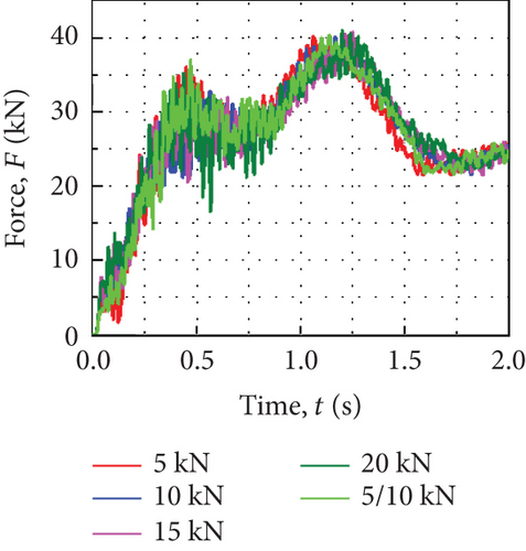
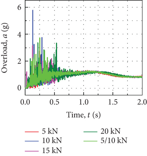
During the suspension conversion process, the rope tears the thermal protection layer and pulls it out from the groove. The relationship between the rope and the thermal protection layer is complicated, which will affect the movement of the return cabin. So, it needs to be considered. Here, five different pull-off force values of the heat-proof are analyzed, namely, 5, 10, 15, 20 (both sides), and 5 (one side)/10 kN (the other side). The initial speed during the conversion process is 8 m/s.
Figure 10(a) shows the variation of the rope loads of the return cabin with time under different pull-off forces. Results show that with the increase of the pull-off force of the thermal protection layer, the load of the ropes gradually increases at the initial stage during the suspension conversion process, then the thermal protection layer is completely pulled off, and the rope buried in the groove of the thermal protection layer is pulled out. The load changes under different pull-off force conditions are basically the same. Figure 10(b) is the curve of the overload of the return cabin over time. When the pull-off force of the thermal protection layer increases, the peak overload of the cabin fluctuates. Therefore, the change in the pull-off force of the thermal protection layer has a certain effect on the pulling out of the hanging rope from the groove of the layer, which affects the motion characteristics of the cabin. However, due to the short duration of the tearing process of the thermal protection layer (~0.31 s), when the pull-off force changes within the specific range (5~20 kN), the effect on the rope load is weak. Besides, the different pull-off force values of both sides have little effect on the overload of the whole cabin and can be ignored.
5. Conclusion
- 1.
Compared with the traditional dynamic analysis method, the coupling relationship between the rope and the heat-proof structure can be described more accurately by the finite element analysis method. Simplified aerodynamic calculation of parachute and introduction of dynamic iterative aerodynamic load subroutine can reduce the amount of calculation and provide an efficient analysis method for dynamic analysis of reentry capsule;
- 2.
Under standard engineering conditions (8 m/s landing speed and 5 kN pull-off force), the peak force of the hanging rope is 40.6 kN, the process of pulling off the thermal protection layer by the hanging rope lasts for about 0.28 s, and the overload peak of the return cabin is about 2.7 g;
- 3.
The rope load and the return cabin overload increase slightly as the initial speed of the system increases from 8 to 10 m/s, and the kinetic energy grows with respect to the initial value;
- 4.
The load of rope gradually increases during the suspension conversion process in the initial stage, but the effects of pull-off force on the rope load are limited due to the short duration time of the tearing process.
In the process of aerospace product design, numerical simulation is the most important means of product design. This article accurately models the dynamics of the suspension conversion process for the return capsule of the new-generation manned spacecraft test ship, which is of great significance for its design and proves the effectiveness of this configuration. The design of this configuration is of great significance for improving the safety and environmental adaptability of the return capsule. This provides important support for the design of China’s new-generation manned spacecraft.
Conflicts of Interest
The authors declare no conflicts of interest.
Funding
This work was supported by China Huaneng Group Co. Ltd. Headquarters Technology Project—Research Technology Project on Torque Monitoring and Overload Fault Warning of Wind Turbine Spindle Based on Magnetoelastic Effect (Grant no. HNKJ24-HF15) and the National Key Laboratory of Internal Combustion Engine and Power System (Grant no. skleps-sq-2023-220).
Open Research
Data Availability Statement
The data used to support the findings of this study are available from the corresponding author upon reasonable request.


