MEA Cost Reduction through Manufacturing Approaches and Material-Level Innovation
Abstract
Globally, the demand for proton exchange membrane fuel cells (PEMFCs) has been growing exponentially. For this growth to continue, it is imperative that the cost of PEMFC technology continues to decrease. While most cost reduction strategies focus on a reduction in the loading of platinum group metals (PGMs), for a large portion of the fuel cell community, these approaches are not yet viable as they require advanced system strategies and unification of the system, stack, membrane electrode assembly (MEA), and component teams which is not widely achieved in the broader fuel cell market. Unlike prior discussions on this topic which depend upon the incorporation of novel materials or significantly larger manufacturing volumes, in this overview, more immediately achievable cost reduction methods are examined to determine a reasonable cost target that can be achieved without having to target ultralow PGM loadings. It will be shown that through rational selection of available Pt/C catalysts for specific applications, sourcing of core materials within China, and improvements in the production process to reduce waste, the MEA price can reach levels of <USD 0.06 W−1 even with conventional PGM loadings (e.g., 0.07 mg cm−2 anode and 0.3 mg cm−2 cathode).
1. Introduction
For passenger vehicles, Li-ion battery technology has proven to be a very successful approach to electrifying the drivetrain and replacing combustion engine technology [1, 2]. While there are still challenges to overcome, such as range anxiety, relatively low specific energy density, long charging time, and limited lithium resources [3], Li-ion batteries appear better positioned than proton exchange membrane fuel cells (PEMFCs) for this application [1]. Conversely, for heavy-duty vehicles and transport trucks, the requirements of fast refueling, long-distance driving, and need for light weight power solutions (to enable larger payloads to be delivered) make PEMFCs ideally suited for these vehicles [4]. In China, these vehicles account for only ~10%–15% of all the vehicles on the road, yet they contribute to ~80% of the total pollution [5]. Thus, there is strong motivation within China (and globally) to electrify the drivetrain of these commercial vehicles using PEMFCs.
While promising, the reality is that the cost of PEMFC technology must be decreased before it can begin to be widely utilized. At the heart of any PEMFC product is the membrane electrode assembly (MEA), which is ultimately responsible for generating the electric power for the PEMFC stack/system. While different fabrication methods are possible, MEAs are most commonly comprised of seven layers: anode frame, anode gas diffusion layer (GDL), anode catalyst layer (ACL), membrane, cathode catalyst layer (CCL), cathode GDL, and cathode frame. Of these components, the anode and cathode layers are widely considered the most critical in terms of cost reduction, as they contain the platinum group metal (PGM) catalysts required to catalyze the electrochemical reactions. While it is true that the ACL and CCL are key factors in the cost, achieving ultralow cost MEAs requires MEA companies to put a strong emphasis on each of the seven-layer components as even relatively inexpensive materials (such as the frame) can have a significant impact on the final MEA cost due to wasted material during the manufacturing process.
In this work, cost reduction strategies will be discussed to outline what approaches have been used to decrease the MEA cost by >50% over the past 3 years and what further steps can be used in the future for additional cost reduction. Importantly, while the majority of the available literature which discusses MEA manufacturing costs focuses on cost projections which assume that advanced catalysts will be utilized, ultralow PGM loadings will be achieved [6, 7, 8, 9, 10], or very high manufacturing volumes (enough to support >500,000 vehicles as discussed by James et al. [11]), the present article aims to discuss what can be realistically achieved in the industry now by independent MEA suppliers. This is a key differentiating factor, as independent MEA suppliers cannot rely on advanced stack/system strategies to ensure “optimal” MEA conditions and, rather, must develop robust MEAs while also working to keep costs as low as possible. With that in mind, the following discussion focuses on what steps can presently be used to help reduce cost without drastically reducing the PGM content in the MEA or having to utilize advanced PGM catalysts which may have high activity but limited durability.
2. Experimental
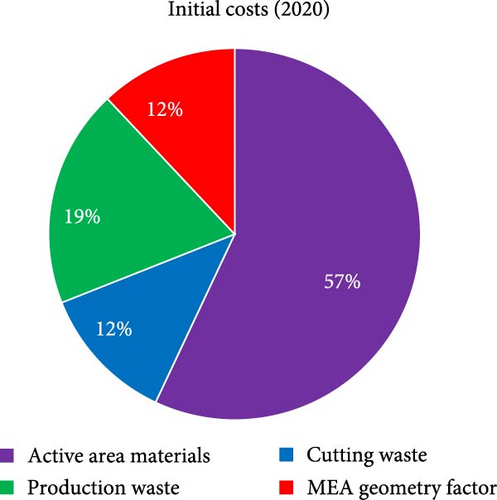
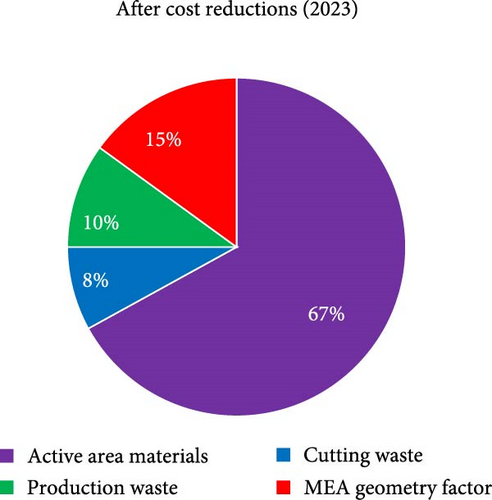
For theoretical approach, in order to discuss MEA cost, it is first critical to define how the cost is to be reported and how to categorize each type of cost. As there is no “standard” size of MEA, the most convenient approach is to normalize the value as USD cm−2Active-Area or USD W−1 as this allows for more universal comparisons to be made, and this is the approach that will be used here. To categorize the cost, there are again many equally valid approaches. In the discussion that follows, only the direct materials cost is considered. The direct material cost is further broken down into four categories (Figure 1): (i) active area materials, (ii) cutting waste, (iii) production waste, and (iv) MEA geometry factor.
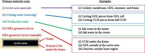
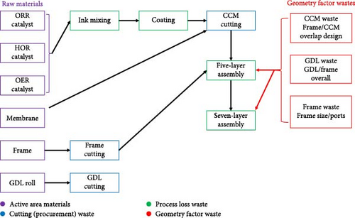
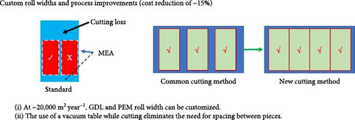
The active area material cost for the purpose of this discussion refers only to the materials directly within the active area that contribute to generating power. Reducing this cost is critical as cost savings at this stage are cascaded through the manufacturing process. Currently, achievable approaches to reducing the active area material costs consist of (i) reducing the amount of PGMs in the MEA, (ii) use of thinner membranes, and (iii) negotiating better prices for raw material/economies of scale. When considering cost reductions based on reduction in the PGM content of the MEA, beginning-of-life (BOL) performance, end-of-test (EOT) performance, durability, and tolerance toward contamination must all be carefully considered. Cutting waste refers to how efficiently the catalyst-coated membrane, gas diffusion layer (GDL), and frame can be cut from the incoming roll of membrane and GDL, respectively. The production waste relates to any process step which generates waste, including mixing/coating the ink, defective/rejected five-layer (framed catalyst coated membrane (CCM)), or seven-layer (GDL attached to five-layer) parts. Finally, the MEA geometry factor refers to any portion of the CCM or GDL which is not directly contributing to power output of the MEA. This includes CCM that is under the frame or GDL that is extending over the active area (Figure 1). While not directly generating power, this “waste” is required for sealing of the MEA (CCM under the frame) and adhering the GDL to the frame. As an MEA supplier, there is very little that can be done about the MEA geometry factor because the unit cell design comes from the stack designer. Thus, the primary efforts for cost reduction must be focused on the remaining three waste categories. At a high level, the key steps considered for cost reduction are summarized in Figure 2.
3. Results and Discussion
3.1. Realistic PGM Loading Constraints
There are various reports in literature of “ultralow” PGM-loaded CCMs with cathode loadings of ~0.1 mg cm−2 [14, 15, 16], and the US Department of Energy (DoE) has set a total PGM loading target equating to 0.1 mg cm−2 Pt (cathode) and 0.025 mg cm−2 (anode) [17, 18]. Furthermore, it has been reported that the Toyota Mirai [19] has succeeded in reducing the anode Pt loading to ~0.025 mg cm−2 and the cathode loading to ~0.17 mg cm−2, giving great hope to the broader fuel cell industry that such low loadings are viable. However, a word of caution is required when considering this information from the perspective of an independent MEA supplier (of which there are now many in the industry).
Specifically, it needs to be recognized and acknowledged that large companies such as Toyota have a fully integrated design team and strategy, with the system, stack, MEA, and even component teams working together to overcome technical challenges. This is critically important as discussions regarding cost tradeoffs at each level (component, MEA, stack, and system) are held together, and advanced system level strategies can be developed which can help to overcome MEA and/or component level failure modes/risks. Examples of such strategies include hybridization and voltage clipping to minimize Pt dissolution [20], N2 purge or ensuring rapid gas exchange during air/air events [21, 22], and the use of cell voltage monitoring (CVM) pins to prevent damaging reversal events [23, 24]. The importance of having a fully aligned strategy, and advanced system-level solutions, was highlighted when the US DoE examined the Generation 1 Toyota Mirai. At that time, few MEAs were believed to be able to survive ~5,000 hr of operation in harsh automotive conditions, yet Toyota had succeeded in achieving this. For many in the industry, it was believed that Toyota must have developed highly advanced MEA technology [11, 19]. However, when the MEAs used in the Mirai were put through standard accelerated stress tests (ASTs), significant degradation was observed. Conversely, when MEAs which had been used in the Mirai for 3,000 hr were evaluated, they showed almost no observable degradation [25]. Had the exact same MEA been used in another (less sophisticated) system, it is highly unlikely it would have survived 3,000 hr. Therefore, while literature reports of ultralow loadings and Toyota’s reported Pt loadings in their second-generation Mirai are intriguing, it is unlikely that such technology is ready for the majority of the industry. Related to this point, Toyota has published their own recommended durability testing which is more suitable for predicting MEA lifetime when the MEAs are used in systems which have been well designed to help minimize MEA-level stressors (such as their own) [19]. This work highlights that it is erroneous to simply look at published PGM loadings and assume that because one MEA has achieved a certain loading level, that technology is now ready for the broader fuel cell market.
For independent MEA suppliers, a greater degree of caution is required, and realistic expectations must be set for PGM loadings with the understanding that the end users of these MEAs have not developed ideal stack/system strategies that perfectly match with the MEA design strategy that was taken. With these points in mind, the percent cost savings vs. Pt loadings (as well as general risks) for the anode and cathode are highlighted in Figure 3. The risk levels are clearly somewhat subjective but are based on literature reports for various MEA-level failure modes [13, 26, 27, 28] combined with internal data/experience from the authors and provide insight into what loadings are currently being used in the broader fuel cell industry.
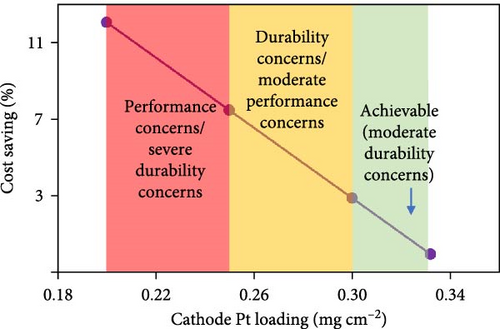
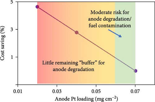
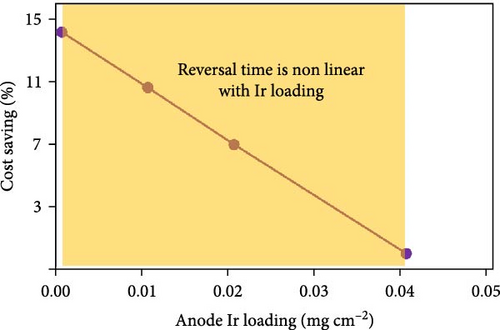
With this mind, in the following analysis, the starting point for PGM loadings is assumed to be 0.33 mgPt cm−2 (cathode) and 0.07 mgPt cm−2 (anode). From here, only minimal PGM reductions are assumed, with final loading targets of 0.3 mgPt cm−2 (cathode), 0.06 mgPt cm−2 (anode), and 0.015 mgIr cm−2 (anode). Thus, the primary discussion for cost savings is focused on opportunities in manufacturing and sourcing of low-cost Chinese MEA components.
3.2. Achievable Short-Term Cost Reductions
3.2.1. Active Area Materials
Due to the sluggish kinetics of the oxygen reduction reaction (ORR) reaction occurring in the cathode, a high activity catalyst and/or high loadings of catalyst are needed. Commercially, Pt/C is the most commonly used ORR catalyst as it provides a good balance between activity and stability. Most cost reduction efforts for PEMFCs have focused around methods to reduce PGM loadings through the use of novel catalysts with enhanced activity vs. traditional Pt/C [7]. Broadly, there is a concerted effort to achieve “ultralow” PGM-loaded CCMs with cathode loadings of ~0.1 mg cm−2 [14, 15, 16]. In this regard, two general approaches have been taken: (1) novel Pt catalyst structures and (2) novel carbon/noncarbon supports.
At the catalyst level, advanced designs such as Pt alloys, core–shell, shape controlled, and nanoframe catalysts have all been explored [10]. While promising at the rotating disk electrode (RDE) level, utilizing such catalysts in an actual product is challenging as the improved activity does not always translate well into the MEA, and these advanced catalysts often suffer from more severe degradation than traditional Pt/C when utilized in an MEA [6, 29]. Although some companies such as Toyota have succeeded in utilizing Pt alloy catalysts [30], many new system manufacturers do not yet have sufficiently sophisticated system-level mitigations in place to prevent the base–metal from dissolving. In terms of catalyst supports, new carbon structures have been developed which help to improve Pt utilization through reducing transport losses, prevention of ionomer binding to the catalyst surface, and improved Pt anchoring to the support which reduces Pt agglomeration/dissolution [7, 14, 31, 32]. It should be noted that nonprecious metal catalysts (NPMCs) have also been investigated [33, 34, 35, 36], but due to the relatively low site density and low stability of these catalysts vs. Pt/C, their practical application has been limited [35].
The use of novel carbon supports [31, 37, 38] is advantageous in that they do not require advanced system-level strategies and thus could be more widely utilized than some of the novel Pt alloys and structures which have been developed. However, these novel support structures are still not widely available commercially. Therefore, such solutions are generally not viable options currently for independent MEA suppliers. Thus, for the present discussion, the achievable cost reduction using currently available (Pt/Ketjen or Pt/Vulcan carbon (VC)) catalysts will be presented.
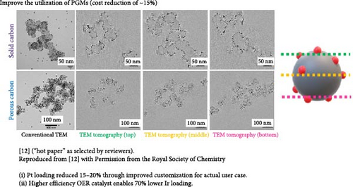
For the cathode, rather than attempt to reduce Pt loadings below 0.3 mg cm−2, a lower risk approach is to tailor the catalyst structure based on the specific application. Specifically, it is known that the structure of the carbon support has a large influence on the polarization curve [12, 39]. When Pt is deposited primarily within the pores of the carbon structure, the mass activity is typically high (high fuel efficiency), but the high current density performance is poor (lower peak power). Conversely, when Pt is deposited primarily on the outer surface of the carbon structure, the mass activity is poor (due to ionomer poisoning of the Pt surface), but the peak power is high due to facile mass transport of reactants [2, 4, 7, 12, 14, 31, 40]. An example of this was recently published by our group, comparing the polarization curves of Pt/Ketjen (Pt resides within the pores of the carbon) vs. Pt/VC (Pt resides on the outer surface (Figure 4) [12].
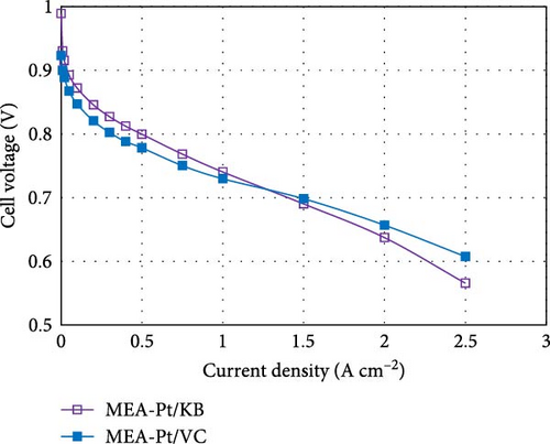
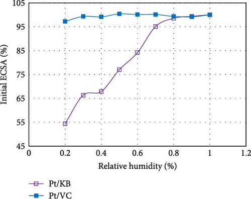
By targeting the right catalyst design for the specific operating strategy of the customer, reductions in Pt loading can be achieved with minimal impact to performance. For example, Pt/Ketjen catalysts can achieve >20 mV higher performance vs. Pt/VC at current densities <1.5 A cm−2. Thus, for applications such as delivery vehicles, which primarily operate at low current densities, a Pt/VC catalyst would require >2x higher loading than a Pt/Ketjen catalyst to achieve the same performance (based on standard Butler–Volmer kinetics). This knowledge can be used to help minimize the cathode Pt loadings without significantly impacting performance in the desired operating window.
While loading concerns are generally well understood for the cathode, the potential impacts at the anode are often underappreciated/overlooked. This is likely due to the fact that the rapid hydrogen oxidation reaction (HOR) kinetics result in a relatively small polarization at the anode such that, as a simple approximation, the anode kinetic losses can be estimated through a linearization of the Butler–Volmer equation [7, 41]. Previous work [41] has demonstrated that there is essentially no impact to the polarization curve until the anode loadings reach values of ≤0.025 mg cm−2. However, this does not mean that loadings of 0.025 mg cm−2 should be targeted as doing so provides no “buffer” for anode degradation. Furthermore, as loadings approach <0.05 mg cm−2, the sensitivity toward contamination becomes extreme [27]. Overall, when compared against the relatively modest decrease to cost from lowering the anode loading (Figure 3), there is little motivation to decrease the anode Pt loading to <0.06 mg cm−2.
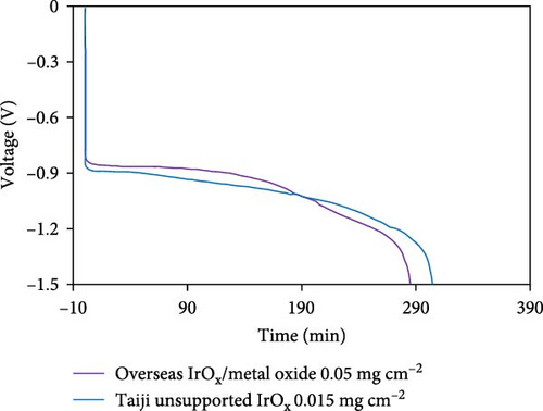
In a fuel cell stack, occasionally one or more MEAs in the stack become H2 starved due to blockages in the flow field (from ice, dust, debris, etc.). When this occurs, the anode potential is driven to very high (>2 V) values leading to rapid oxidation of the carbon support [42, 43, 44]. To mitigate this, an oxygen evolution reaction (OER) catalyst is often incorporated into the anode layer to promote water oxidation in favor of carbon corrosion during these “reversal” events [28, 44, 45]. The most commonly use OER catalysts for this application are Ir, Ru, or alloys of these two metals [46, 47]. Due to the extremely high cost of Ir relative to Pt, there is strong motivation to reduce the Ir content in the anode catalyst layer. One approach has been to develop IrRu alloys, which generally result in higher activity toward the OER (due to the enhanced OER activity of Ru vs. Ir), thus enabling lower Ir loadings. However, it has also been demonstrated that these alloys do not generally possess unique physical properties but, rather, provide activity/durability which is essentially the same as a physical mixture of IrOx/RuOx in similar proportions to the “alloy” composition [48, 49]. It is well established that Ru is far less stable than Ir at OER relevant potentials [50], and thus, the durability of these IrRuOx alloys is inversely proportional to Ru content. With the negative effects of Ru crossover also well-established [51, 52], these facts when taken together make IrRuOx alloys less attractive than pure IrOx. Additionally, to achieve small particle sizes and to improve overall stability, these IrOx or IrRuOx alloys are often deposited on metal oxide supports such as TiOx, NbOx, or TaOx [53, 54, 55]. Unfortunately, even small amounts of dissolution of metal oxides can lead to negative interactions in the membrane and/or cathode catalyst layer [56, 57]. Therefore, if a IrRuOx or supported IrOx/metal oxide OER catalyst is used, improved anode durability (higher Ir loadings) must be weighed against the possible negative effects on the membrane and/or cathode catalyst layer. This is problematic as anode durability requirements vary significantly between customers depending on their operating strategy/abilities, and thus, the ability to adjust Ir loadings independent of other MEA considerations is quite important. For these reasons, Guangdong Taiji Power focused on the development of a pure unsupported IrOx OER catalyst (TJ-Ir80) which can be used to tune the durability of the anode relatively independently of other MEA characteristics. The activity and durability of Ir-based catalysts depend on multiple factors, including the size/shape/crystallinity of the initial particles [58, 59, 60]. These properties were each evaluated through an extensive design of experiment development project, resulting in a highly promising unsupported IrOx catalyst which achieves an optimal tradeoff between activity and durability. The use of this material enables a significant decrease in IrOx loading (from 0.05 to <0.015 mg/cm2) and thus MEA cost, without sacrificing anode durability (Figure 5(a)). Finally, it should be noted that an alternative strategy for mitigating reversal events is the use of cell voltage monitoring (CVM) pins [61]. In this case, all (or some portion) of the cells are continually monitored, and the system can then react appropriately if the CVM pin detects a reversal event. Assuming CVM pins are used every two to four cells in the stack, the cost to the system of adding CVM pins would be ~4 USD kW−1 [62]. With current prices of Ir (~170 USD g−1), a loading of 0.015 mg cm−2 and an assumed power density of 1.4 W cm−2, the use of Ir would add ~2 USD kW−1 which makes this approach quite competitive vs. CVM pins.
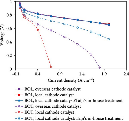
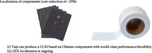
In addition to reductions in PGM content, the use of Chinese components (membrane, catalyst, and GDL from Chinese companies) can also be used to reduce cost (for example, TJ-Ir80 is ~10% less expensive than imported IrOx catalyst). In the case of Chinese ORR catalysts, BOL performance is already world-class, but the durability has not yet reached the same level as overseas suppliers. To overcome this, Taiji has developed posttreatment steps that can be used to greatly improve the durability to the same level (or higher) as catalysts supplied from outside of China (Figure 5(b)). Furthermore, with many Chinese component suppliers, the cost/volume curve plateaus relatively quickly, with “high-volume” pricing being achieved at MEA quantities of ~500,000 per year. This enables further cost reductions at relatively moderate MEA sales volumes.
3.2.2. Cutting Waste
For suppliers of GDL and membrane, there is a standard roll width which they produce. At low volumes, if “custom” roll widths are required, the supplier will provide the desired roll width but will still charge the customer for the wasted material that is slit from the “mother roll.” However, once larger volumes are reached, these suppliers will adjust the width of the mother roll to achieve custom roll sizes. The volumes at which this can be achieved depends on each supplier, but within China, this can be done even at volumes of ~20,000 m2 year−1 (internal information obtained from Taiji’s supply chain department).
3.2.3. Production Waste
Production waste is related to waste during process steps (such as the holdup volume in the mixing/coating steps) and rejected parts (such as at the five-layer or seven-layer assembly steps). Process waste during mixing/coating can be reduced through improving the shelf life of the ink, which reduces the frequency with which the mixers/coaters need to be cleaned. Reducing the number of rejected parts is a combination of negotiations with downstream customers and continuous improvements of manufacturing steps/reduction of defects. Negotiating with customers regarding what is a “defect” can be a difficult task, with the “burden of proof” placed on the MEA supplier. It is important to identify and communicate the difference between “visual defects” and “functional defects.” An example of a visual defect would be discoloration of the GDL caused by MPL bleed-through or smoothing of the fibers leading to differences in how light is reflected. While these issues may have no impact on the key functions of the GDL, subscale and even stack level testing may be required before the customer is comfortable accepting it. An example of a functional defect would be a bubble in the frame in the area of the frame that sits beneath the seal in the unit cell. This could lead to leaks and represents a serious risk at the stack-level. Identifying and setting the quality standards with each customer are clearly a critical step before “production waste” can actually be quantified.
Reducing the quantity of functional defects in the product can appear challenging, but the efficiency of this process of improvement can be greatly enhanced by following six-sigma methodologies such as the define, measure, analyze, improve, and control (DMAIC) steps. Using these process steps in an iterative approach is often the most effective way to minimize rejected parts and reduce production waste.
3.2.4. MEA Geometry Factor Waste
While this particular form of waste is controlled primarily by the customer (stack developer), some general comments can still be made. Specifically, the overlap between the CCM and frame is required to reduce the risk of leaks occurring in the MEA. Reducing the overlap can help to reduce MEA geometry factor waste but comes with unacceptably high risk. Furthermore, there are no rapid accelerated stress tests (ASTs) that can be used to rapidly screen and quantify the risk, as leaks occurring under the CCM/frame region of the MEA typically occur after many thousands of hours of operation if the frame peels from the CCM. Thus, the simplest way to reduce the overall contribution of this waste factor is to enlarge the active area such that the overlap area under the frame is a smaller percentage of the total CCM area. This comes with additional stack/unit cell design considerations but, from an MEA perspective, allows for lower cost (in terms of USD cm−2 or USD W−1) designs.
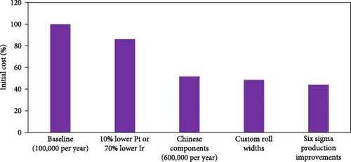
Figure 6 summarizes the steps that have been taken to reduce overall cost while maintaining Pt loadings of ≥0.3 mg cm−2 (cathode) and ≥0.06 mg cm−2 (anode). As is shown, since ~2018 within China, the sales price has been significantly reduced from ~0.13 USD W−1 to 0.06 USD W−1 without having to take large risks in reducing total PGM loadings or the use of novel catalysts. A review of literature in this field reveals price projections ranging from 0.014 to 0.09 USD W−1 [63]. However, as previously stated, such studies are mostly cost “projections” and are based on highly optimistic assumptions around reduction in PGM loadings [11, 64]. They are not proven to be achievable sales prices nor do they utilize commercially relevant loadings/materials. A more meaningful comparison is to the cost of Gore’s CCM in 2017, which was reported to be 0.092 USD cm−2 [60]. For an “apples-to-apples” comparison, the 0.13 USD W−1 reported here as the starting price for MEAs in China in the 2018 timeframe must first be converted to USD cm−2. To do this, a typical power density of 1.4 W cm−2 is assumed, resulting in ~0.18 USD cm−2. Next, since the Gore price is for a roll of CCM, the contribution to the 0.18 USD cm−2 from the GDL, frame, cutting waste (from both CCM and GDL), MEA geometry factor, process waste during framing, seven-layer assembly, and leak testing must all be removed. From the data in Figure 6 (a), and acknowledging that ~75% of the MEA cost comes from the CCM [11, 64], the CCM contribution to the MEA price in 2018 within China was ~0.1 USD cm−2 which compares reasonably well to the stated price of Gore’s CCM in 2017. Importantly, what is shown in the current work is that this overall price was reduced by 54% without having to incorporate high risk/advanced materials and without having to sacrifice durability. It is the authors’ opinion that further cost reductions will be difficult to achieve in the near-term, particularly for independent MEA suppliers which must build in a certain degree of “durability buffer” (meaning limits on PGM reductions) into the design since such suppliers must assume that the end user may not have fully compatible system strategies and/or limited knowledge themselves in how to minimize stress on the MEA when utilized in a commercial product.
4. Conclusions
While there are numerous government reports and literature describing MEA costs, the majority of these reports are focused on future projections, assumptions of high volumes, and the use of low platinum group metal (PGM) loadings (e.g. ≤0.125 mg cm−2 total loadings). In this work, we examine what is currently achievable with available materials and reasonable volumes of ~20 km2 CCM/year. The MEA manufacturing costs are categorized as (i) active area materials, (ii) cutting waste (sourcing), (iii) production waste, and (iv) MEA geometry factor. The challenges in utilizing advanced catalysts and/or attempting to significantly reduce PGM loadings when operating as an independent MEA supplier are discussed, and a lower limit of 0.3 mg cm−2 (cathode) and 0.06 mg cm−2 (anode) is recommended. With this limit, the achievable cost reductions through rational selection of catalyst based on customer need (porous vs. non porous carbon), sourcing of raw materials from within China, negotiating for custom roll widths, and improvements to cutting processes during manufacturing are investigated. It is shown that through these steps, the sales price of the MEA can be reduced from ~0.13 to 0.06 USD W−1 without having to introduce significant risk into the design. To achieve appreciable cost reductions in the coming years, new materials will likely be needed such as high O2 permeable ionomers [65, 66], advanced Pt-based catalysts [67, 68, 69], or lower cost membrane/ionomers. Until these materials are readily available and produced in high enough volumes to reduce cost, it is unlikely that significant cost reductions can be achieved from the current values without introducing unacceptably high risk.
Disclosure
The manuscript was presented at the EFCF 2023.
Conflicts of Interest
The authors declare no conflict of interest.
Acknowledgments
We acknowledge the financial support from the National Natural Science Foundation of China Research Fund for International Excellent Young Scientists (22250610201), the Innovation Team of Universities of Guangdong Province (2020KCXTD011), the Engineering Research Center of Universities of Guangdong Province (2019GCZX002), the Key-Area Research and Development Program of Guangdong Province (2020B090920001), and the Guangdong Key Laboratory for Hydrogen Energy Technologies (2018B030322005).
Open Research
Data Availability
The data that support the findings of this study are available on request from the corresponding author. The data are not publicly available due to privacy or ethical restrictions.


