Development of Mixed Matrix Membranes by Using NH2-Functionalized UiO-66 and [APTMS][AC] Ionic Liquid for the Separation of CO2
Abstract
The ever-escalating CO2 concentration in the atmosphere calls for accelerated development and deployment of carbon capture processes to reduce emissions. Mixed matrix membranes (MMMs), which are fabricated by incorporating the beneficial properties of highly selective inorganic fillers into a polymer matrix, have exhibited significant progress and the ability to enhance the performance of a membrane for gas separation. In this research, an amine-based ionic liquid (IL) [APTMS][AC] was prepared, which has greater CO2 affinity and greater solubility due to its amine moiety. The metal–organic framework (MOF) UiO-66 with a multidimensional crystalline structure was used as a filler due to its appropriate porosity and tunable properties, and it was functionalized with NH2. MOFs were further modified with an IL to prepare UiO-66@IL and UiO-66-NH2@IL, and MMMs incorporating each MOF were fabricated with the polymer Pebax-1657. All the prepared membranes and MOFs were characterized to predict their separation efficiency. Several characterization techniques, namely, FTIR spectroscopy, XRD, and SEM, were used to successfully synthesize UiO-66@IL and UiO-66-NH2@IL composites and confirmed proper dispersion and excellent polymer‒filler compatibility at filler loadings ranging from 0 to 30 wt.%. The separation performances were investigated, and the results showed that the incorporation of RTIL with the highly crystalline structure and large surface area of UiO-66 enhanced the separation efficiency of the membrane. The permeability of CO2 for all fabricated membranes continuously increased with increasing filler concentration, wherein the permeability was comparatively high for the UiO-66-NH2 MMMs. The CO2/CH4 selectivity improved by 35%, 54%, and 60%, respectively, for UiO-66@IL, UiO-66-NH2, and UiO-66-NH2@IL MMMs compared to simple UiO-66 for CO2/CH4 and by 28%, 36%, and 63%, respectively, for CO2/N2, with an increase in filler loading in the MMMs.
1. Introduction
Global warming has drawn unprecedented attention from researchers to CO2 emissions, as CO2 concentrations are increasing to an alarming extent. The use of alternative energy sources has thus received much attention. The industrial sector uses natural gas and fossil fuels excessively as primary energy sources, and the burning of these fossil fuels results in pollution and the release of large amounts of CO2, SO2, and NOx into the atmosphere. It mainly contains CH4 (55%–60%), along with CO2 and other trace gases (H2, N2, H2S, etc.). CO2 is a significant contributor to global warming, leading to an increase in global temperature [1]. Consequently, there is a dire need to vigorously control CO2 emissions with a low energy penalty. The major consequences of global warming in the Earth’s atmosphere include a decrease in ice content, an increase in the Earth’s temperature, sea level rise, and deforestation. Moreover, the presence of CO2 in gas resources is dangerous, reduces the calorific value, and enhances corrosion abilities [2].
To overcome this problem, different strategies have been developed, including membrane separation technology to separate flue gases from other gas streams. According to the Intergovernmental Panel on Climate Change (IPCC), a modern power plant equipped with appropriate carbon dioxide capture and storage (CCS) technologies could reduce CO2 emissions by 80%–90%. Carbon capture and storage (CCS) is one of the best approaches and has been widely acknowledged as an efficient and effective way to control the rapid increase in greenhouse gas concentrations. Generally, CCS technology mainly focuses on three basic CO2 separation and capture processes: precombustion carbon capture, storage, oxyfuel processes, and postcombustion capture [3, 4]. This technique can remove up to 90% of CO2 discharged from different sources, such as chemical industries, hydrogen manufacturing plants, and electricity stations, and prevent CO2 from entering the atmosphere [4, 5]. In recent years, CCS technology has been broadly applied in industries such as cement production plants, fertilizer industries, and hydrogen manufacturing plants.
In the past few decades, numerous technologies have been developed and investigated on an industrial scale to capture CO2 from various gas streams, such as adsorption [6, 7], cryogenic distillation [8, 9], physical or chemical absorption [10], and membrane technology [11, 12, 13]. New materials with applications in these techniques, i.e., metal organic frameworks (MOFs), ionic liquids (ILs), deep eutectic solvents (DESs), and gas hydrates, have emerged. Among these technologies, membrane-based gas separation is considered a more promising technique for removing CO2 from different gas streams and has gained more attention due to its intrinsic benefits compared to other traditional separation processes, such as energy savings, low operating costs, high energy efficiency, and environmental sustainability [11, 12]. Researchers have been putting their efforts into developing more efficient and robust membranes for capturing CO2. Innovative research is needed to enhance membrane separation efficiency and surpass the upper bound limit defined by the Robeson plot by developing new membranes with high permeability and selectivity [14].
In the last few years, different membranes have been developed that have the potential to surpass the attractive area defined by the “Robeson upper bound,” named mixed matrix membranes (MMMs) [15]. MMMs are a combination of inorganic and organic membranes and can potentially cause upper-bound complications [16]. Inorganic membranes have better selectivity and high thermal stability, whereas polymer membranes are more porous and highly flexible; hence, combining these materials can improve the permeability and selectivity of membranes [17]. MMMs have high gas separation abilities and are fabricated by incorporating an inorganic filler dispersed in a polymer matrix [18, 19]. These membranes were developed using a wide variety of inorganic fillers, such as carbon molecular sieves, silica, zeolites, and activated carbon [20]. Despite the fact that numerous novel materials have been synthesized and developed, a few have achieved commercial success in gas separation applications [21]. Some challenges for developing high-performance MMMs include the suitable selection of materials, proper particle dispersion of inorganic materials, and proper interfacial contact between the inorganic filler and polymer matrix [22].
Metal–organic frameworks (MOFs) were first discovered in 1965 [23]. They are highly porous crystalline structures comprising multivalent metals and multitopic organic chains. Currently, researchers have extensively investigated these materials to address compatibility problems and have used them efficiently to develop defect-free membranes [24]. Several MOF structures have been prepared and used as fillers in MMMs and have attracted the attention of researchers due to their attractive features, such as large porosity, large pore volume, breathing effects, and tailorable properties [25].
Ionic liquids (ILs), a novel class of organic solvents that were first used in 2001 by Blanchard for the separation of CO2, have been the focus of research during the last few years [26, 27]. Ionic liquids have been categorized as ILs into different types of membranes, including supported IL membranes (SILMs), polymerized IL membranes (PILs), polymer–IL composites, and three-component mixed matrix membranes [28]. A few publications have focused on ILs and IL membranes in recent years, but they have not specifically focused on CO2 separation [29, 30, 31]. Room-temperature ionic liquids (RTILs) are prepared by combining organic anions and cations. These are liquid salts at ambient temperature and have many significant applications [26]. Ionic liquids (ILs) exhibit distinctive properties, i.e., low volatility, nonflammability, the potential to replace volatile organic solvents, very low melting below 100°C and boiling points, and particularly excellent CO2 solubility. Moreover, their selectivity makes them attractive candidates for gas separation applications [32, 33, 34].
In this study, we synthesized the MOF UiO-66 [35], functionalized it with an NH2 group, and then synthesized the MOFs UiO-66 and UiO-66-NH2 modified with the IL [APTMS][AC] to prepare UiO-66@IL and UiO-66-NH2@IL composites. MMMs were fabricated from these composites to investigate their ability to separate CO2. Very recently, our research team used RTILs to develop MMMs (Figure 1) and achieved unprecedented results in the separation of CO2 [29, 30, 31]. The developed RTIL (3-aminopropyl) trimethoxy silane and acetic acid exhibited high affinity for the separation of CO2 [36].

In this research article, the well-known MOF UiO-66 with the formula (Zr6O4 (OH)4 (O2C-C6H4-CO2)6) was used as a filler in the development of MMMs due to its outstanding ultrahigh thermal and chemical stability [37]. Furthermore, by using different derivatives, UiO-66 BDC linkers can be easily functionalized and provide a series of UiO-66 derivatives, e.g., UiO-66-NH2, UiO-66-COOH, and UiO-66-NO2. Among the products of UiO-66, UiO-66-NH2-based MMMs have attracted unique interest [38]. In the framework of UiO-66-NH2, the N atoms can improve the adsorption capacity of CO2 and the selectivity due to the dipole–quadrupole and base–acid interactions between the basic N sites and CO2 molecules [39]. Moreover, UiO-66-NH2 also exhibits excellent hydrothermal stability and shows better CO2 separation selectivity than the simple MOF UiO-66.
2. Methods
2.1. Materials
Zirconium chloride (ZrCl4 anhydrous) was purchased from Merck (Germany), and (3-aminopropyl)-trimethoxy silane was purchased from Sigma Aldrich (Germany). Terephthalic acid (H2BDC, 99%) and amino terephthalic acid (H2BDC-NH2, 99%) were procured from Acros Chemicals (Belgium), and N-dimethylformamide (DMF≥99.8%) was procured from CARLO ERBA Reagents (France). Acetic acid was purchased from Daejung Chemicals (Korea). Methanol and ethanol were purchased from Fisher Chemicals. All reagents were used as received without any purification. Pebax-1657 was obtained from Arkema (France).
2.2. Ionic Liquid Synthesis
In a typical synthesis of 3-(trimethoxysilyl) propan-1-aminium acetate [APTMS][Ac] (Scheme 1), 0.1 mol of (3-aminopropyl)-trimethoxy silane was gradually added to a two-necked flask, and then acetic acid was added dropwise under cooling conditions. This synthesized mixture was stirred for 12 hr at room temperature. In the end, the resulting mixture is dried using a rotary evaporator, resulting in a yellow viscous product [36].

2.3. Synthesis of MOF (UiO-66) and UiO-66-NH2
The UiO-66 material was synthesized by a solvothermal process according to the reported literature [40]. To synthesize UiO-66, equimolar amounts of H2BDC (3.5 mmol, 0.58 g) and ZrCl4 (3.5 mmol, 0.82 g) were dissolved in 40 ml of DMF, and the resulting mixture was stirred until it was completely dissolved. The resulting solution was sonicated and placed in an oven for 24 hr, and the temperature was set at 120°C. After the completion of the reaction, the product was centrifuged and washed several times with methanol and DMF. Finally, the final UiO-66 crystals were dried overnight at 105°C [37].
By following a similar procedure, UiO-66 was functionalized with NH2 groups.
2.4. Preparation of Ionic Liquid Composites with UiO-66 and UiO-66-NH2
IL incorporated UiO-66 sample was prepared by the wet impregnation method [41]. UiO-66 was kept for drying overnight in an oven at 105°C and the flat petri dish was fully wrapped with aluminum foil to avoid any humidity and impurities. One gram IL was added to 20 mL ethanol, and the beaker was tightly packed with parafilm to avoid any loss of solvent. The mixture was kept stirring at ambient temperature for 2 hr. Then, 1 g MOF (UiO-66) was added to the already prepared solution, and the mixture was stirred at room temperature for 2 hr. After achieving a homogenous solution, it was centrifuged and washed three times with ethanol. As a result, the solvent (ethanol) was completely evaporated, and the sample was placed in the oven overnight. The final product UiO-66@IL composite was obtained in powder form. To prevent any impurities and moisture, the product was labeled and stored in desiccators [42].
IL [APTMS][AC] composites with MOF UiO-66-NH2 were prepared by following the same technique.
2.5. Preparation of Mixed Matrix Membranes
The solution casting method was used to synthesize MMMs with different filler loadings (0−30 wt.%). The UiO-66@IL dry powder was placed overnight in an oven at 105°C to remove any absorbed moisture. A certain amount of UiO-66@IL was dissolved in an ethanol–water solution by a sonication bath to ensure a homogenous solution. To obtain a homogenous polymer solution, a calculated amount of Pebax particles was dissolved in an ethanol–water mixture containing 70 wt.% ethanol and 30 wt.% water with mechanical stirring at reflux for 2 hr at 80°C. The Pebax solution was allowed to cool to approximately25°C, and then a homogenously dissolved UiO-66@IL solution was added to this Pebax solution and stirred for 1.5 hr. The resulting solution was cast in a flat Teflon dish and allowed to dry for 24 hr at ambient temperature with an overturned funnel. Finally, the membranes were dried for another 24 hr in an oven at 40°C [43]. By following the same procedure, UiO-66-NH2@IL membranes with 10%, 20%, and 30% filler loadings were fabricated for comparison, and the coding of the prepared membranes based on filler loading is given in Table 1.
| Membranes | Composition |
|---|---|
| Pebax | Pure Pebax + 0% filler |
| Pebax-UiO-66-10 | 10% UiO-66 + 90% Pebax-1657 |
| Pebax-UiO-66-20 | 20% UiO-66 + 80% Pebax-1657 |
| Pebax-UiO-66-30 | 30% UiO-66 + 70% Pebax-1657 |
| Pebax-UiO-66-NH2-10 | 10% UiO-66-NH2 + 90% Pebax-1657 |
| Pebax-UiO-66-NH2-20 | 20% UiO-66-NH2 + 80% Pebax-1657 |
| Pebax-UiO-66-NH2-30 | 30% UiO-66-NH2 + 70% Pebax-1657 |
| Pebax-UiO-66@IL-10 | 10% IL modified UiO-66 + 90% Pebax-1657 |
| Pebax-UiO-66@IL-20 | 20% IL modified UiO-66 + 80% Pebax-1657 |
| Pebax-UiO-66@IL-30 | 30% IL modified UiO-66 + 70% Pebax-1657 |
| Pebax-UiO-66-NH2@IL-10 | 10% IL modified UiO-66-NH2 + 90% Pebax-1657 |
| Pebax-UiO-66-NH2@IL-20 | 20% IL modified UiO-66-NH2 + 80% Pebax-1657 |
| Pebax-UiO-66-NH2@IL-30 | 30% IL modified UiO-66-NH2 + 70% Pebax-1657 |
2.6. Characterization
The crystallinity of the UiO-66 particles and the prepared mixed matrix membranes (MMMs) was determined by X-ray diffraction (XRD) (PANalytical X’pert Pro) with Cu-Kα radiation at a voltage of 45 kV and 40 mA in the 2θ range of 5°–50°. To confirm the successful synthesis of the material, the successful incorporation of the fillers was studied by a Spectra Thermo-Nicolet 6700P FTIR Spectrometer. The morphology of the MMMs and filler UiO-66 were examined by a TESCAN Vega3 LMU at different voltages. The membrane morphology and proper dispersion of the filler in the polymer matrix were examined by using scanning electron microscopy (SEM Philips XL30 FEG). The samples for SEM images were prepared by breaking the membranes using liquid nitrogen, and then the prepared samples were covered with a gold layer using a Cressington HR 208 (UK). A gas pycnometer (G-DenPyc 2900, Gold App Instruments) was used to determine the densities of the MMMs. A Ubbelohde viscometer was used to determine the viscosity at ambient temperature. The glass transition temperature of the prepared membrane predried at a temperature of 120°C was analyzed by a TA instrument DSCQ1000 at a 10°C/min heating rate.
2.7. Gas Permeation Measurement Test
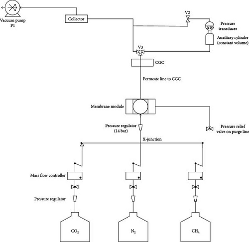
The mixed matrix membrane gas separation performance for both pure and mixed gas streams (CH4, CO2, and N2) was analyzed by performing permeation in a custom-built setup. This apparatus was used to evaluate gas penetration across each membrane. Gas permeation membranes were mounted on porous metallic plates and sealed tightly with Viton O-rings. A back-pressure regulator was used to adjust the upstream pressure on the gas purge line. The composition of the permeate and retentate was determined using a compact gas chromatograph (CGC, YL Instruments, South Korea) equipped with a thermal conductivity detector [29].
A schematic layout of the permeation setup is shown in Figure 2; a description of its operation and specifications can be found elsewhere [30]. A constant feed pressure of 10 bar was maintained throughout the system. In addition, feed gas injection rates of I L/min were maintained between 298 and 338 K [44]. Equation (1) was used to calculate the gas permeability Pi determined by the solution diffusion mechanism and is represented as follows:
3. Results and Discussions
3.1. Ionic Liquid Characterization
The physical properties of the prepared ILs are shown in Table 2. The viscosity of ILs is of great importance in evaluating gas separation performance, and low-viscosity fluids are recommended for gas separation applications. Its high viscosity (521.32 cp) can be attributed to the presence of silyl moieties in its structure [36]. The IL [APTMS][AC] density (1.2 g/cm3) is similar to the water density (1 g/cm3). The molar volume is another significant factor for gas separation performance, and ILs with lower molar volumes are well suited for gas separation applications [39].
| Molecular weight (g/mol) | Viscosity (cP) | Density (g/cm3) | Molar volume (cm3/mol) |
|---|---|---|---|
| 281.42 | 521.32 | 1.2 | 234.51 |
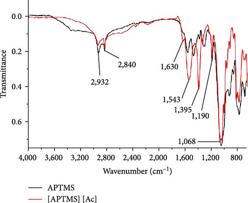
Figure 3 shows the FTIR spectra of the synthesized ILs. For Ac, the peaks at 1,755 and 1,703 cm−1 reveal the stretching vibrations of C═O and the asymmetric deformation of CH3 at 1,402 cm−1 [37]. The strong peaks visible at 3,000 cm−1 for O─H also provide evidence for the presence of Ac. The characteristic peak at 2,926 cm−1 is attributed to the stretching of C─H bonds in the IL [APTMS][AC] [37]. The bands at 1,190 cm−1 are the result of the vibrational stretching of C─N. In addition, the strong and visible peaks at 1,540 and 1,399 cm−1 indicate the symmetric and antisymmetric stretching vibrations of C─O, respectively. These peaks represent the successful synthesis of the IL. The disappearance of the broad O─H stretching peak at 3,000 cm−1 and the appearance of significant symmetric and asymmetric C─O stretching peaks at 1,543 and 1,395 cm−1, respectively, indicate the successful synthesis of the IL [36].
3.2. Characterization of the Fillers
The morphologies of both the unmodulated MOF UiO-66 and the functionalized UiO-66 showed rectangular shapes, and the particle size did not change substantially with modulation; moreover, the particle size of the prepared MOFs was approximately 100–200 nm, which was previously investigated by our research group [45]. This is in agreement with the typical particle size of UiO-66, which reportedly falls within the range of 0.2–0.5 μm, as reported by Su et al. [46]. For the MOF NH2-UiO-66, which is a variant of UiO-66 functionalized with amino groups (NH2), the particle size of NH2-UiO-66 reportedly depends on the synthesis conditions and the amount of HCl used as a modulator during synthesis. Lee et al. [47] reported NH2-UiO-66 with a size range of 100–300 nm, which is within that which has been observed by our research group. For IL-impregnated MOFs, IL impregnation reportedly does not alter the MOF particle size, as shown in our research group’s recent work in Iqbal et al. [40].
The calculated BET surface areas of the prepared MOFs UiO-66 and NH2-UiO-66 were 1,476 and 940 m2/g, respectively. The properties of the synthesized MOFs are expressed in Table 3, which indicates that both materials are highly porous, as measured by the t-plot method [48].
| MOF | BET surface area (m2/g) | Vmicroporea (cm3/g) |
|---|---|---|
| UiO-66 | 1,476 | 0.509 |
| NH2-UiO-66 | 940 | 0.260 |
- aMeasured by the t-plot method.
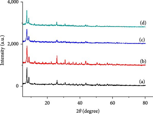
Figure 4 shows the XRD patterns of the UiO-66 and UiO-66-NH2 MOFs and the UiO-66@IL and UiO-66-NH2@IL fillers. The large characteristic peak at 2.4° confirms the successful formation of UiO-66, as do several peaks at 8.6°, 26.0°, and 30.8° [40, 49]. The peaks attributed to the UiO-66 and UiO-66-NH2 fillers are consistent with the reported literature. Modification with the IL [APTMS][Ac] decreases the intensity, but the integrity is not greatly affected. There is a gradual decrease in crystallinity, which shows the successful incorporation of RTIL into the pores of fillers (UiO-66@IL and UiO-66-NH2@IL) [50].
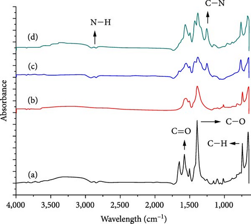
FTIR analysis of the MOF and filler UiO-66 and UiO-66@IL, UiO-66-NH2, and UiO-66-NH2@IL membranes are presented in Figure 5. For all the samples, the stretching bands near 1,655 cm−1 correspond to C═O bonds. The peaks at 1,450–1,600 cm−1 indicate the incorporation of CC bonds. The bands at 747 and 666 cm−1 are ascribed to the C─H bond of the H2BDC ligands. The broad peaks at 3,445 and 3,360 cm−1 validate the existence of the N─H bond of the amino group from 2-aminoterephathalic acid. The peak at 1,259 cm−1 corresponds to the C─N bonds of aromatic amines [51]. All the observed characteristic peaks were consistent with those reported in the literature [40]. In the case of pure UiO-66, the most significant peak corresponding to the symmetric stretching of C─O occurs at 1,394 cm−1 in UiO-66@IL, and the most significant peak occurs at 1,394 cm−1. The peak position shift is due to the addition of the IL to the MOF. Notably, there are no significant differences between UiO-66@IL and NH2-Ui0-66@IL and the parent MOFs UiO-66 and UiO-66-NH2, which represents complete exfoliation of the IL into its parent MOFs. However, minor differences could be a result of functional moieties of the IL[APTMS][AC] precursors that interact with the MOF.
A parameter that is at times reported in research that utilizes MOFs for CO2 separation is the CO2 adsorption capacity of the MOFs, which is determined through CO2 adsorption testing. However, these data are more commonly reported for studies that are based on sorption/desorption separation rather than membrane-based separation. Examples of the former include works such as those of Luu et al. [52] and Cao et al. [53]. Luu et al. [52] reported that NH2-UiO-66 MOF could reach approximately 110–120 cm3/g CO2 adsorption capacity at 10 bar, with the amine-functionalized MOF having a slightly greater capacity than UiO-66 despite the former having a lower specific surface area (similar to our data in Table 3). Yang et al. [54], in a study that also involved MMM fabrication and testing, also reported a negative effect of IL grafting on the specific surface area of the MOF (UiO-66-(OH)2@PIL) as well as its CO2 adsorption capacity (at 1 bar), which decreased from 100 to 83 cm3/g. Despite this, the study mentioned that IL impregnation improved MOF dispersity in the membrane matrix due to the hydrophilicity of the IL, and likewise, the study reported improved permeability and selectivity of the MMMs. This highlights that when MOFs are incorporated into MMMs for gas separation, their gas adsorption capacity plays a role in determining the membrane’s performance, but it is not the only factor and not the strongest correlation. Instead, a stronger correlation exists between the CO2 adsorption enthalpy at high CO2 loadings and the CO2 permeability of the corresponding MMM, as reported by Thür et al. [55] for MOF-808. This explains why several MOF-based MMMs [56, 57, 58, 59] do not report CO2 adsorption isotherm data and instead rely on studying whether the incorporation of MOFs, functionalized MOFs, and IL-impregnated MOFs will yield improved permeability (through sorption/desorption-facilitated transport) and/or improved selectivity (through selective sorption/desorption).
To test the abovementioned theory that MMM separation performance is not directly correlated with MOF adsorption performance, we performed a machine learning (ML) experiment to determine the expected CO2 and CH4 adsorption performances of the two MOFs used in our study. The ML model was built in Mathematica v14.0, and the regression method used was random forest. This exercise consisted of two stages. In the first stage, the few works that present both MOF adsorption isotherm and MMM separation performance data and are similar to the present study, namely, those of Gong et al. [60] and Wang et al. [61], were used as training data for the ML model. The model was trained using permeability, selectivity, pressure range, gas composition, and temperature data and using the qs and b Languir coefficients fitted to the isotherm data (pressure (P) versus amount adsorbed (q)) presented in the published works according to Equation (4). Figures 6(a) and 6(b) show the predicted isotherms of our MOF based on the separation performance of our MMM. In the second ML modeling stage, data from a large number of studies [62, 63, 64, 65, 66, 67, 68] that reported MOF adsorption performance (but not MMM) were used as the ML training data. The training data included the specific surface area, pore volume, and fitted qs and b Languir coefficients. Figures 6(c) and 6(d) show the predicted isotherms of our MOFs based on their physical properties:
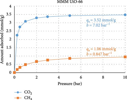
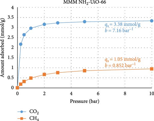
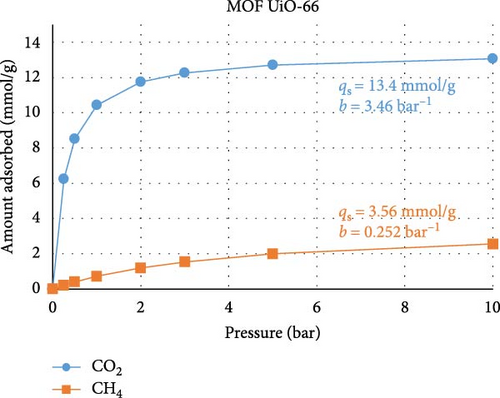
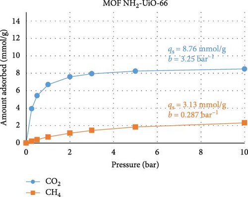
There are three main points that the isotherms and their Langmuir equation fitting parameters transmit about the MOFs used in the present study and how they behave when inserted into MMMs for gas separation. First, the isotherms predicted from the MMM separation performance (Figures 6(a) and 6(b)) are characterized by smaller values of qs, namely, the adsorption capacity, and larger values of b, namely, the adsorption response rate, compared to the isotherms predicted from the MOF adsorption performance (Figures 6(c) and 6(d)). This confirms that the separation performance is not directly related to the adsorption capacity, as during membrane separation, the MOF will not operate under equilibrium conditions, so its adsorption performance is seemingly less efficient than when the MOF is tested under equilibrium conditions, when in reality, the MOF is operating under transient conditions during separation processes where the adsorption response rate is more important. Second, the isotherms for UiO-66 MOF had greater CO2 adsorption capacity than did those for the modified NH2-UiO-66 MOF, while the adsorption capacity for CH4 was similar. This confirms that the MOF modification is meant to improve the separation performance more than simply its adsorption capacity. Third, the substantially larger adsorption capacity and adsorption response rate of the MOFs for CO2 over CH4 are beneficial for improving the selectivity of the MMMs.
The use of ML in predicting adsorption performance can be reliably accomplished when the properties of the MOF and their utilization conditions are similar to those in the training data, as confirmed by the expected performance illustrated in Figure 6, but care is needed to avoid inconsistent training data. In compiling the studies herein used for ML training, one work [69] was excluded from the analysis due to its isotherm having unrealistic fitting parameters, which resulted from the isotherms having a high adsorption amount even at zero pressure. The inclusion of invalid data causes ML predictions to become rigid and thus fail to respond accurately to changes in input parameters. Our ML models were validated by ensuring that parametric changes in input parameters resulted in the expected changes in adsorption behavior.
3.3. Membrane Characterization
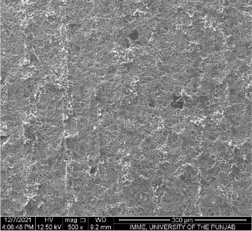
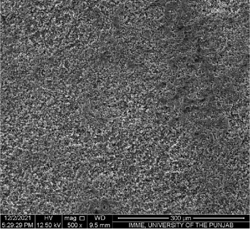
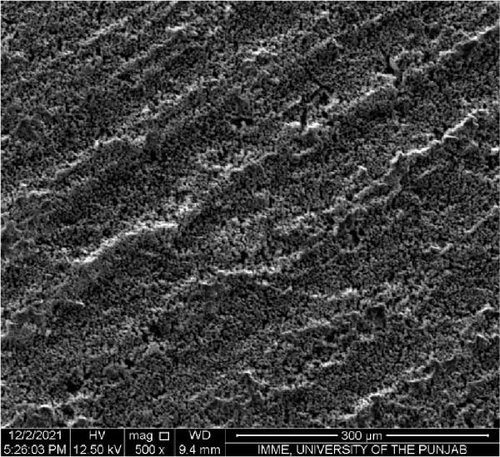
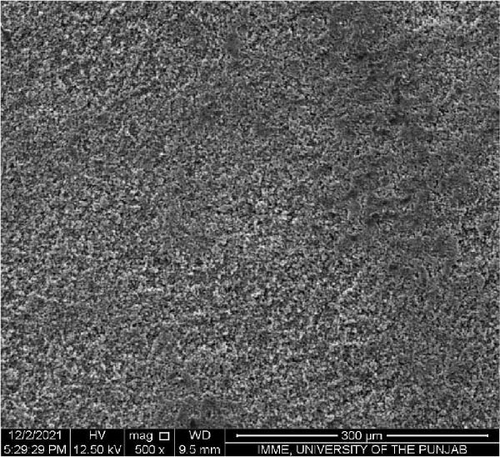
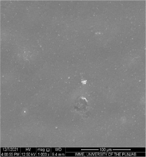
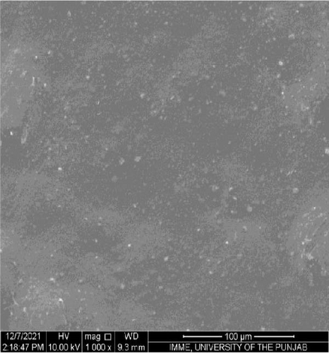
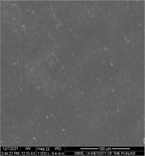
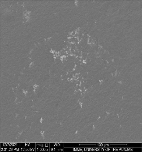
SEM was performed to investigate the dispersion of UiO-66, UiO-66-NH2, UiO-66@IL, and UiO-66-NH2@IL in Pebax-1657; surface and cross-sectional (freeze-fractured in liquid N2) SEM images of all MMMs were acquired. Figure 7 illustrates the smooth and uniform surface texture of the synthesized MMMs with MOFs with a thickness of approximately 300 μm. The Pebax-1657 membrane had a uniform and highly smooth structure, and no noticeable defects were observed. However, changes occurred with the incorporation of the IL, and these changes intensified with increasing filler loading from 10 to 30 wt.%. These changes are only observed on the membrane surface and are consistent with previous research [70, 71, 72]. According to the cross-sectional images (Figure 8), the IL was uniformly distributed throughout the membrane, and the interfacial adhesion was strong. There is no evidence of agglomeration or sedimentation. An increase in the RTIL was only associated with small changes. There was good compatibility between the polymer and the IL. The reason may be that the IL occupies a high free volume in the hydrophobic polymer due to its contorted molecular structure [73].


The separation performance of the prepared MMMs was studied for pure gas as well as mixed gas streams, and the obtained results were compared with those of the pure Pebax membranes (0% filler), as shown in Tables 4 and 5. The gas separation performance was determined to analyze the proper dispersion of the filler in the membranes. There was a successive increase in the permeability of CO2 with increasing filler concentration in all the membranes prepared. The mixed matrix membranes with 30 wt.% UiO-66 exhibited a 90% increase in permeability relative to that of the polymer membranes and a minor decrease in selectivity from 21.4% to 21.5% for CO2/CH4 and CO2/N2, respectively. The increase in the pure gas CO2 permeability is associated with the effective separation ability as well as greater diffusivity [74]. The highly porous structure of UiO-66 may facilitate diffusion and provide excessive pathways for gas transportation [75].
| Membrane | Permeability (Barrera) | Performance ratio | ||||
|---|---|---|---|---|---|---|
| Filler conc. (%) | CO2 | CH4 | N2 | CO2/CH4 | CO2/N2 | |
| UiO-66 | 0 | 82 | 3.80 | 1.70 | 21.58 | 48.24 |
| 10 | 102 | 5.60 | 2.22 | 18.27 | 46.08 | |
| 20 | 123 | 6.95 | 2.92 | 17.70 | 42.12 | |
| 30 | 156 | 9.20 | 4.12 | 16.96 | 37.86 | |
| UiO-66@IL | 0 | 82 | 3.80 | 1.70 | 21.58 | 48.24 |
| 10 | 98 | 4.12 | 1.89 | 23.87 | 52.03 | |
| 20 | 114 | 4.19 | 1.93 | 27.28 | 59.23 | |
| 30 | 124 | 4.26 | 2.01 | 33.68 | 61.69 | |
| UiO-66-NH2 | 0 | 82 | 3.80 | 1.70 | 21.58 | 48.24 |
| 10 | 90 | 4.09 | 1.74 | 22.00 | 51.72 | |
| 20 | 112 | 4.13 | 1.89 | 27.17 | 59.38 | |
| 30 | 138 | 4.18 | 2.12 | 33.12 | 65.30 | |
| UiO-66-NH2@IL | 0 | 82 | 3.80 | 1.70 | 21.58 | 48.24 |
| 10 | 88 | 3.84 | 1.65 | 22.77 | 52.99 | |
| 20 | 110 | 3.87 | 1.68 | 28.42 | 65.48 | |
| 30 | 135 | 3.92 | 1.72 | 34.44 | 78.49 | |
- aBarrer ≡ (mol·m)/(m2·s·Pa).
| Membrane | Permeability (Barrer) | Selectivity ratio | ||||
|---|---|---|---|---|---|---|
| Filler conc. (%) | CO2 | CH4 | N2 | CO2/CH4 | CO2/N2 | |
| UiO-66 | 0 | 74/78 | 3.78 | 1.69 | 19.58 | 46.15 |
| 10 | 95.4 | 5.45 | 2.25 | 17.51 | 43.56 | |
| 20 | 116 | 6.87 | 2.83 | 16.89 | 39.65 | |
| 30 | 143 | 10.3 | 3.97 | 13.83 | 35.52 | |
| UiO-66@IL | 0 | 74/78 | 3.78 | 1.69 | 19.58 | 46.15 |
| 10 | 97.5 | 4.31 | 1.87 | 22.63 | 50.45 | |
| 20 | 107 | 4.39 | 1.90 | 24.37 | 57.37 | |
| 30 | 121 | 4.56 | 1.99 | 26.54 | 58.79 | |
| UiO-66-NH2 | 0 | 74/78 | 3.78 | 1.69 | 19.58 | 46.15 |
| 10 | 83.5 | 4.05 | 1.72 | 20.60 | 49.73 | |
| 20 | 103 | 4.10 | 1.85 | 25.12 | 52.43 | |
| 30 | 129 | 4.15 | 2.01 | 31.08 | 58.87 | |
| UiO-66-NH2@IL | 0 | 74/78 | 3.78 | 1.69 | 19.58 | 46.15 |
| 10 | 80.4 | 3.84 | 1.62 | 20.92 | 51.44 | |
| 20 | 103 | 3.86 | 1.63 | 26.68 | 52.15 | |
| 30 | 127 | 3.90 | 1.65 | 32.56 | 70.50 | |
In the case of UiO-66@IL, there was a remarkable improvement in the permeability of CO2—51.2%—along with a higher selectivity, from 35 to 28%, for CO2/CH4 and CO2/N2, respectively. This improved selective behavior of UiO-66@IL can be attributed to the incorporation of a novel IL with a higher affinity for CO2 due to the existence of silyl bonds and polar amine groups as well as better solubility. The permeability of the UiO-66-NH2 membranes significantly increased compared with that of the UiO-66 membranes by 70%, ranging from 82 to 139 Barrer, due to the incorporation of amino groups in the organic ligands of UiO-66 [76]. As illustrated in Table 4, it also exhibited a significantly improved selectivity of up to 54% and 36% for CO2/CH4 and CO2/N2, respectively. In the case of UiO-66-NH2@IL, the permeability of CO2 increased to 65% from 82 to 135 Barrer, and the selectivity increased to 60% for CO2/CH4 and 63% for CO2/N2.
The permeability of CO2 is slightly better in the UiO-66-NH2 membrane than in the UiO-66 membrane because of the incorporation of amino groups in the organic ligand of UiO-66. Amine-UiO-66-based mixed matrix membranes interact with CO2 molecules via CO2-philic functionalities, such as the presence of nitrogen in UiO-66-NH2-based membranes, which are N2-phobic and CO2-philic in nature, resulting in the lower solubility of nonpolar gases such as N2 and CH4 and the higher solubility of polar gases such as CO2 [77]. Moreover, the greater affinity and smaller size of CO2 compared to the N2 molecules come into existence between the fundamental N2 molecules and highly acidic CO2 molecules, resulting in the greater permeability of CO2 than of N2 and CH4 [70, 71].
In addition, UiO-66-NH2@IL exhibited the highest selectivity over all other fabricated membranes when RTILs and amino-functional groups were added. The existence of the NH2 group contributed to enhancing the CO2 affinity and IL attributed to the high CO2 solubility and providing sorption sites.
The mixed gas permeability and selectivity (50/50 wt.%) of both gases for all membranes are illustrated in Table 5. The overall trend for both gases was the same. The permeability and ideal selectivity of mixed gas are lower than those of pure gas. This comparative reduction in values is carried out by competitive sorption due to the presence of N2 and CH4 molecules in the feed mixture, which hinders the diffusion of CO2 molecules across the membranes [78].
3.4. Effect of Filler Loading on the Solubility and Diffusion Coefficients of CO2
The solubilities and diffusivities of the UiO-66, UiO-66@IL, UiO-66-NH2, and UiO-66-NH2@IL MMMs are shown in Table 6. For the UiO-66 membranes, the results exhibited a consistent increase in diffusivity with increasing filler concentration. This can be explained by the large surface area of the UiO-66 particles, which allows rapid diffusion of CO2 molecules in membranes. Therefore, the high gas permeability may result from the better gas diffusivity [71]. In contrast, the solubility of UiO-66 is lower than that of the other membranes because the rigid structure of UiO-66 prohibits additional sorption sites for gas transportation.
| Type of MOF | Filler conc. (%) | Diffusivity (10−8 cm2/s) | Solubility (10−2cm3/cm3·cmHg) |
|---|---|---|---|
| UiO-66 | 0 | 50.0 | 1.64 |
| 10 | 59.0 | 1.73 | |
| 20 | 78.0 | 1.57 | |
| 30 | 103 | 1.52 | |
| UiO-66@IL | 0 | 50.0 | 1.64 |
| 10 | 49.3 | 1.98 | |
| 20 | 54.0 | 2.12 | |
| 30 | 57.6 | 2.15 | |
| UiO-66-NH2 | 0 | 50.0 | 1.64 |
| 10 | 55.43 | 1.63 | |
| 20 | 63.0 | 1.78 | |
| 30 | 69.0 | 2.00 | |
| UiO-66-NH2@IL | 0 | 50.0 | 1.64 |
| 10 | 53.4 | 1.63 | |
| 20 | 60.0 | 1.83 | |
| 30 | 64.4 | 2.09 | |
For UiO-66@IL-based mixed matrix membranes, the diffusivity is lower than that of UiO-66 membranes due to the highly viscous nature of the IL, leading to small pathways for the diffusion of gas molecules. Furthermore, the high solubility of CO2 can be attributed to the combined effect of the methoxy group, acetate ions, and amine group. IL contains a methoxy group, which acts as a cation and exhibits a high affinity for CO2. Acetate ions are also responsible for elevated CO2 solubility and have a high absorption capability [36].
For UiO-66-NH2, the diffusivity and solubility increased with increasing filler loading. At the same time, the diffusivity is relatively lower than that of the UiO-66 membranes due to the presence of the NH2 group. The amino group enhances the CO2 affinity, which may increase the solubility of CO2 but reduce its diffusivity. Similarly, the diffusivity and solubility improved with increasing filler loading in UiO-66-NH2@IL [71].
3.5. Effect of Temperature on CO2 Permeation
The permeability of CO2 was investigated as a function of temperature ranging from 298.15 to 338.15 K for all the membranes, and the results are shown in Figure 9. The permeability of all the membranes increased consistently with temperature. The UiO-66 membranes (with 30% filler loading) exhibit the highest permeability of 200.2 Barrer due to their highly porous structure and effective separation capability. Then, the permeability of UiO-66-NH2 improved from 138 to 175 Barrer. The permeability of CO2 increased with increasing temperature due to the flexibility of polymer chain movement attributed to enhancing the fractional volume at elevated temperatures [79]. In addition, for the UiO-66-NH2@IL membranes, the permeability of CO2 improved from 135 to 170 Barrer. The UiO-66@IL membranes demonstrated the slightest increase in permeability with increasing temperature. The membranes modified with IL showed the least permeability.
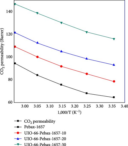
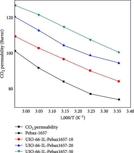
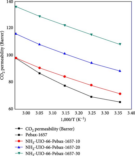
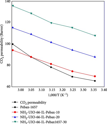
The activation energies of all the fabricated MMMs are shown in Table 7. For all types of membranes, the activation energy of CO2 consistently decreased with increasing temperature. CO2 molecules with a kinetic diameter of 0.34 nm require a minimal amount of activation energy for permeation. Moreover, with increasing filler concentration, the activation energy for the UiO-66@IL and UiO-66-NH2@IL membranes decreased, probably due to the incorporation of the IL. RTILs contain functional groups that eventually increase stiffness, so more activation energy is needed [80].
| Filler concentration (%) | Activation energies Ep (KJ/mol) | |||
|---|---|---|---|---|
| UiO-66 | UiO-66@IL | UiO-66-NH2 | UiO-66-NH2@IL | |
| 0 | 8.67 | 8.67 | 8.67 | 8.67 |
| 10 | 6.54 | 6.12 | 6.65 | 6.76 |
| 20 | 5.40 | 5.90 | 5.95 | 6.56 |
| 30 | 4.50 | 5.43 | 5.10 | 6.05 |
The effect of filler concentration on the glass transition temperature is shown in Table 8. There is a consistent increase in the Tg as the filler concentration increases from 0% to 30%. A higher glass transition temperature at a filler concentration of 30% improved the chain rigidity at the interface, indicating excellent filler–polymer adhesion in the mixed matrix membranes.
| Filler concentration (%) | Tg (°C) | |||
|---|---|---|---|---|
| UiO-66 | UiO-66@IL | UiO-66-NH2 | UiO-66-NH2@IL | |
| 0 | −53.0 | −53.0 | −53.0 | −53.0 |
| 10 | −52.0 | −50.0 | −52.0 | −50.3 |
| 20 | −50.3 | −49.3 | −48.3 | −46.5 |
| 30 | −49.0 | −46.4 | −46.5 | −45.0 |
3.6. Effect of the Concentration of CO2 on CO2/CH4 Selectivity
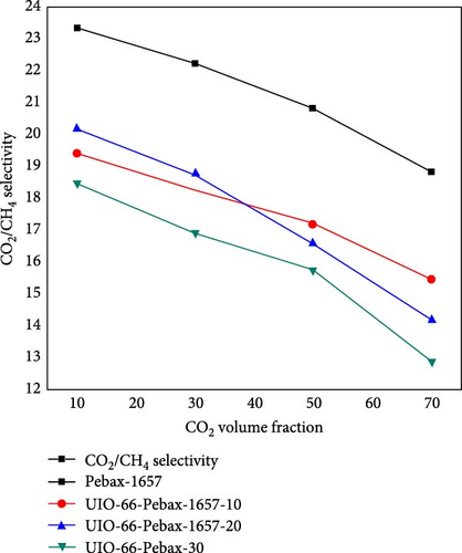
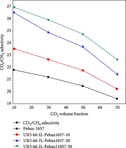
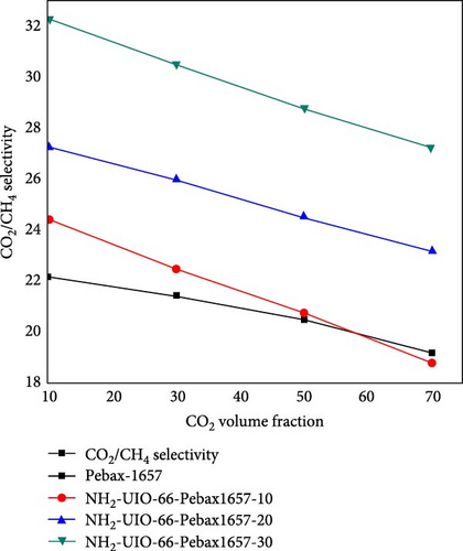
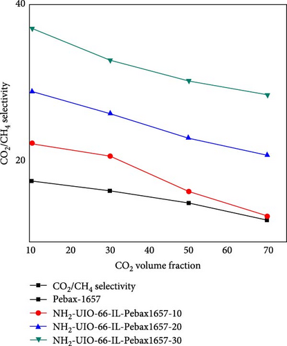
The effect of the concentration of CO2 on the CO2/CH4 selectivity is illustrated in Figure 10. For all types of membranes, the selectivity consistently decreased with increasing CO2 concentration. When the concentration of CO2 increases from a certain level, the problem of plasticization causes swelling of the membrane, deteriorating the polymer chain structure and increasing the chain mobility [81]. As a result, it allows undesirable molecules (i.e., CH4) to pass through it and decrease the selectivity [59].
3.7. Comparison of the Separation Performances of Synthesized MOFs with Those of Other UiO66 Composite-Based Membranes
The CO2 permeability and selectivity of the synthesized UiO-66 MOFs and MMMs with Robeson’s upper bound for analyzing the separation performance of the prepared membranes are given in Table 9 and illustrated in Figure 11. This investigation indicates that the membranes tested here are more effective than previously reported membranes and that the Pebax®1657/UiO-66@IL[APTMS][AC] membrane exhibits excellent permeability and selectivity compared to other membranes, i.e., Pebax 2533, PEBA, and PDMS [85, 87, 38, 89, 90, 91]. The permeability of the ZIF-7/Pebax, ZIF-8/Pebax, and PGO/Pebax MMMs was much better than that of the UiO-66/Pebax and NH2-UiO66/Pebax membranes. However, it can be clearly seen that the CO2 selectivity is greater for our proposed membrane than for previously developed membranes. It appears that our synthesized membranes also overcome the restriction between permeability and selectivity, as reported in the literature. Compared with those of other composite membranes, namely, PEBA-UiO66, Pebax-2533/PGO, ZIF-7/Pebax, and ZIF-8/Pebax, the selectivities of NH2-UiO-66@IL and UiO66@IL/Pebax are the highest, with values of 78 and 62 for CO2/N2 and 35 and 34 for CO2/CH4, respectively. These results demonstrate that the proper dispersion of filler polymers and the correct tuning of MOF outer and inner structures have always been significant challenges for MMMs [38, 88, 92, 93]. This was especially true when considering mixed-gas data and polymers that are inexpensive and readily available on the market.

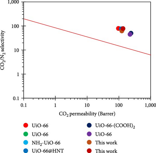
| Polymer | MOF | Loading (wt.%) | PCO2 (Barrer) | Selectivity | Source | |
|---|---|---|---|---|---|---|
| CO2/CH4 | CO2/N2 | |||||
| Pebax®1657 | UiO-66 | 10 | 97 | 22 | 79 | [82] |
| Pebax®1657 | UiO-66 | 10 | 130 | — | 72 | [82] |
| Pebax®1657 | NH2-UiO-66 | 10 | 118 | 30 | 56 | [82] |
| Pebax®1657 | UiO-66@HNT | 20 | 119 | — | 76 | [83] |
| Pebax®1657 | UiO-66- (COOH)2 | 50 | 240 | 18 | 50 | [84] |
| Pebax®1657 | UiO-66 | 59 | 225 | 17 | 45 | [84] |
| Pebax-1657 | ZIF-7 | 30 | 300 | — | 48 | [85] |
| Pebax®1657 | ZIF-8 | — | 199.5 | — | 53.88 | [86] |
| Pebax-2533 | pGO | — | 380.4 | — | 24.19 | [87] |
| PEBA | NH2-UiO-66 | — | 87 | — | 66.1 | [38] |
| PEBA | UiO-66 | — | 96.3 | — | 56.6 | [38] |
| PDMS | Cu3 (BTC)2 | — | 109.2 | — | 33.46 | [88] |
| Pebax®1657 | UiO66@IL | 30 | 124 | 34 | 62 | This work |
| Pebax®1657 | NH2-UiO66@IL | 30 | 135 | 35 | 78 | This work |
4. Conclusion
The current study demonstrated the successful fabrication of MMMs by using a novel IL, 3-(trimethoxysilyl) propan-1-aminium acetate [APTMS][Ac], by using Pebax-1657 as a polymeric matrix and incorporating UiO-66@IL and UiO-66-NH2@IL as fillers for the separation of CO2 from CH4 and N2. The synthesized IL [APTMS][Ac] was effectively incorporated inside the membrane pores and improved the permeability from 82 to 124 Barrer as the filler loading increased from 0 to 30 wt.%, and the structural integrity was verified by XRD, FTIR, and SEM analyses. SEM analysis showed that the filler was well dispersed, and there were no interfacial voids. The synthesized MMMs exhibited excellent permeability and selectivity compared to other reported materials and commercial membranes. Combining RTILs with MOFs functionalized with amino groups (NH2) is a promising approach due to their synergistic ability to maintain high mixed gas selectivity and improved permeability. The unique contributions of functionalized MOFs improved the selectivity for CO2 due to sorption and steric effects. The combination of mixed matrix membranes along with MOFs and different ILs is a powerful new platform in membrane technology for the separation of CO2. These platforms will aid in developing membranes for the commercialization of gas separation processes that will be critical in the coming decades for the production of clean energy and for environmental sustainability.
Disclosure
Asim Laeeq Khan present address: Department of Chemical Engineering, Islamic University of Madinah, Madinah, Kingdom of Saudi Arabia. Note. Some contents of this paper also appear in the thesis of Hafiza Mamoona Khalid titled “Development of MMMs by using UiO-66 and ionic liquid for the separation of CO2” defended in 2019 at the University of the Punjab, Pakistan [94].
Conflicts of Interest
The authors declare that they have no conflicts of interest.
Acknowledgments
The doctoral research of Hafiza Mamoona Khalid is funded by the MINER program of the Advanced Research Projects Agency – Energy (ARPA-E) through grant DE-AR0001711.
Open Research
Data Availability
The experimental data used to support the findings of this study are included within the article.


