A Compact Circularly Polarized Planar Spiral Antenna With Ultrawide Bandwidth and Directional Radiation Pattern
Abstract
A compact circularly polarized (CP) planar spiral antenna with ultrawide bandwidth and directional radiation pattern is proposed for ultra-wideband (UWB) positioning applications. The proposed antenna consists of a dual-arm planar spiral with a tapered microstrip line, two L-shaped metallic shorting stubs, and a square ground plane with four stepped slots. By connecting two L-shaped metallic stubs to both the ends of the dual-arm spiral through metal posts, the traveling wave current path is effectively extended, resulting in a significant improvement of the CP bandwidth. Additionally, both impedance bandwidth and circular polarization performance of the proposed antenna can be enhanced by adopting four stepped slots on the square ground plane. Measured results show that the planar spiral antenna features an impedance bandwidth from 3.23 GHz to 7.0 GHz (more than 73.7%), a 3-dB axial ratio (AR) bandwidth of 62.1% (3.05 GHz–5.8 GHz), and finally achieves an overlapping bandwidth of 56.9% (3.23 GHz–5.8 GHz). On the overlapping bandwidth, this antenna maintains a gain consistently above 6 dBic while the peak gain reaches about 7.4 dBic. The overall size of the antenna is 0.59λg × 0.59λg × 0.17λg (λg is the free-space wavelength at the lowest frequency, 3.23 GHz). Thanks to the ultrawide CP bandwidth and compact size, the proposed antenna can be a promising candidate for UWB positioning applications.
1. Introduction
Applications such as indoor asset localization and personal tracking most commonly employ ultra-wideband (UWB) positioning technology [1]. The inherent properties of the wideband signal enable high-precision positioning, making UWB technology a preferred choice for applications that require positional accuracy within the range of 10–30 cm. In UWB systems, the performance is critically influenced by antenna design. CP antennas are increasingly favored due to their ability to reduce multipath interference and polarization mismatch losses. Thus, the reliabilities and accuracies of the UWB positioning systems can be enhanced by using a CP antenna [2]. To generate CP radiation, two orthogonal modes with equal intensity are combined, and a 90-degree phase difference is introduced between them [3]. CP antennas with simple patch structures are very common but usually have an AR bandwidth of less than 1% [4]. To enhance the radiation capabilities of CP antennas, extensive research was devoted to explore various designs, including multifeed configurations [5, 6], stacked microstrip patch antennas [7–9], slot antennas [10–13], dielectric resonator antennas [14, 15], and aperture antennas [16].
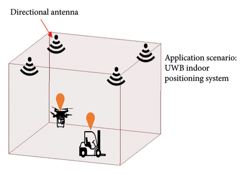
In some actual scenarios, directional antennas are commonly used, especially in applications like ceiling-mounted base stations, as shown in Figure 1. In order to address these practical requirements, a variety of wideband directional antennas with CP radiation have been created. Tapered slot structures and Vivaldi’s approach are frequently employed in the design of UWB CP antennas. The prototype design in [17] achieves an impedance bandwidth of 57.3% and a 3-dB AR bandwidth of 41.4% by incorporating four sequentially rotated tapered patches, a 90° phase delay network, and a circular metal wall as a vertical ground plane. Nevertheless, there are still limitations in terms of impedance matching, AR performance, and miniaturization. To address these problems, a novel approach is proposed by integrating a pair of orthogonally arranged Vivaldi antennas with an innovative wideband feeding network. This method ensures the uniform distribution of signals in orthogonal phases, resulting in a significantly expanded AR bandwidth of 118.4% [18]. However, the practical utility of this antenna design still has limitation due to its large sizes and especially very thick in height. Therefore, the simple structure, wide bandwidth, and flexible shape of crossed dipoles have garnered more attention for the CP antennas. Pairs of orthogonal dipoles integrated with a 90° phase delay lines typically were used to achieve the desired CP radiations [19–23]. The antenna in [19] featuring a rectangular dipole has an axial ratio bandwidth (ARBW) of 27%, which is quite substantial. A crossed bowtie dipole antenna achieved an ARBW of 25.6% [20]. The ARBW notably reached to 51% with the transformation of a symmetrical bowtie arms into an asymmetric configuration [21]. Also, a cavity-backed cross dipole achieves a wide ARBW of 53.4% by using an innovative asymmetrical cross-loop [22]. Despite these advancements, these antennas with high profiles are still not suitable for all system integrations.
The utilization of spiral antennas is a straight-forward solution for attaining broadband CP performance. Typically, the conventional spiral antennas need additional differential feeding port, which are commonly facilitated by wideband baluns [24]. Nonetheless, the incorporation of a wideband balun tends to result in increasing the profile of the antenna. In order to achieve more compact structure without compromising its broadband characteristic, a novel wideband antenna with a pair of curved tapered slots for component integration is reported in [25], but this antenna exhibits a limited CP bandwidth of 34%. The use of mesh reflector of this antenna can enhance CP performance, and also increases the antenna dimensions. In [26], an integrated tapered microstrip line, serving as an impedance transformer, was employed to feed the spiral antenna and replacing the wideband balun effectively. This approach simplifies feeding structure and reduces antenna dimensions. However, the cost of the antenna can also be increased due to the incorporation of an additional stacked planar single-turn spiral and an absorptive resistor.
In this manuscript, a compact planar spiral antenna with ultrawide CP bandwidth and directional radiation pattern is presented and analyzed. An integrated tapered microstrip line serving as an impedance transformer is employed to feed the spiral antenna that can effectively improve the bandwidth performance [26]. In order to improve the CP bandwidth of a spiral antenna, two L-shaped metallic stubs on the ground plane are connected to the arm of spiral through two metal posts. This configuration effectively elongates the path of the traveling wave current without increasing its dimensions. In order to further enhance the CP bandwidth and impedance performance, four stepped slots are introduced on the ground plane. The proposed antenna features low cost, compact size, and wide bandwidth, and thus, it is suitable for UWB positioning applications.
2. Antenna Geometry
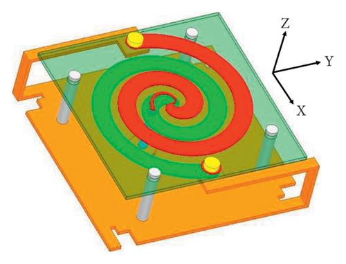
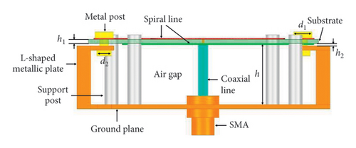
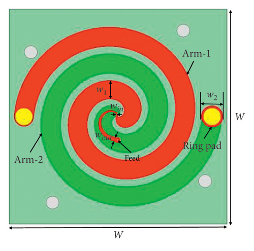
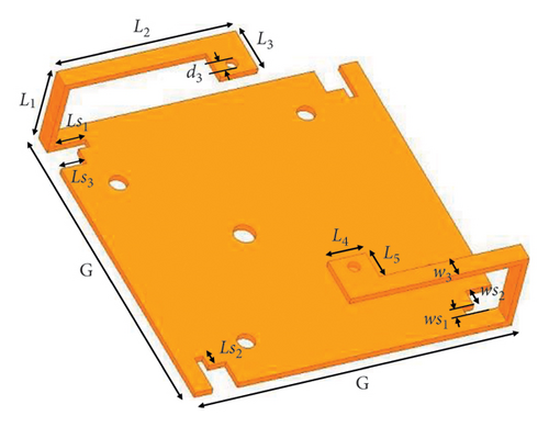
Configurations of the proposed antenna are shown in Figure 2, which are composed of three elements: a spiral antenna, two L-shaped metallic stubs, and four stepped slots on ground plane. In Figures 2(a) and 2(b), a pair of spirals that serves as the main radiating element is fabricated on top and bottom layers of FR4 substrate (FR4 with a dielectric constant of 4.4 and loss tangent of 0.02). Concurrently, a tapered microstrip line with the length of half-turn (π) is connected to arm 1 of spiral antenna and printed on the top layer of the substrate. The coaxial cable that threads the ground plane establishes a perpendicular connection to the spiral antenna. The proposed antenna assembly receives its central feed through a coaxial cable; the cable inner conductor is meticulously soldered to the tapered microstrip line and the outer conductor is connected to both the arm 2 of spiral antenna and the ground plane. To extend current path, both spiral arms are connected to the L-shaped metallic stubs with a metal post. In addition, two L-shaped metallic stubs mounted perpendicularly along the edges of the ground plane can enhance antenna CP performance without enlarging its physical size. The substrate, with a uniform thickness of h1 = 1 mm and dimensions of W × W, is positioned at a height of h = 14 mm above the square ground plane and is suspended at a height of h2 = 0.5 mm over the L-shaped metallic stubs. Figure 2(c) demonstrates that a tapered microstrip line is printed on the top layer of substrate and connecting to arm 1, and arm 2 is printed on the bottom layer serving as the ground plane for the tapered microstrip line of top layer. A ring pad above the terminal of arm 2 is set on the top layer of substrate for antenna assembly. Figure 2(d) illustrates the structure of the ground plane, which includes two L-shaped metallic stubs. Four stepped slots are added on four edges of the ground plane. The use of four stepped slots can enhance both the impedance matching and the CP performances. Ls1 and Ls3 are the lengths of stepped slot and ws1 and ws2 are the widths, respectively. Detailed geometry dimensions of the proposed antenna are summarized in Table 1.
| Parameter | Value (mm) |
|---|---|
| G | 55 |
| W | 50 |
| w1 | 4.5 |
| w2 | 5 |
| w3 | 3 |
| win | 0.38 |
| wout | 0.98 |
| ws1 | 1.5 |
| ws2 | 3 |
| L1 | 14.5 |
| L2 | 31 |
| L3 | 8 |
| L4 | 6.5 |
| Ls1 | 5.5 |
| Ls2 | 2 |
| Ls3 | 4.5 |
| h | 14 |
| h1 | 1 |
| h2 | 0.5 |
| d1 | 4 |
| d2 | 3.2 |
| d3 | 2 |
3. Antenna Design Procedure and Analysis
3.1. Design Procedure
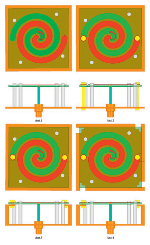
To clearly demonstrate the structural evolution of the proposed antenna, we created models and conducted simulations for four different antennas, as depicted in Figure 3. Our initial investigation focuses on a spiral antenna with a square ground plane that is fed by a tapered microstrip line, which we refer to as Ant.1. Ant.1 is a traditional spiral antenna with ground plane and is capable of producing directional radiation. Based on Ant.1, the spiral arms of Ant.2 have been shorted to ground plane by a pair of metal posts. So, current reflections at the terminations of the spiral arms can be reduced. In Ant.3, two L-shaped metallic stubs are strategically positioned along the border of the ground plane. They are attached to the spiral arms via a pair of metal posts. So, current reflections at the ends of the spiral arms can be further reduced efficiently by two L-shaped metallic stubs. As for Ant.4, four stepped slots are added at four edges of the ground plane to enhance impedance and CP performances. The designed approach of the main radiator of Ant.1 is similar to that in [26]. To attain a directional radiation for Ant.1, a square ground plane has been placed beneath the spiral antenna. A coaxial cable is inserted from the ground plane into the spiral antenna, and the outer conductor of coaxial cable is connected to the ground plane.
The reflection coefficients and ARs of the proposed four different antennas are exhibited in Figure 4. The AR bandwidth of Ant.1 is significantly degraded when the spiral design comprised arms with a limited number of turns and a ground plane. One reason for the degradation is current reflections occurring at the terminations of the spiral arms and the other reason is tight electric field coupling from the ground plane. The CP performance can be improved by increasing the number of spiral turns and increasing the height between the spiral and the ground plane. Nevertheless, the modifications will result in an enlargement of dimensions of the antenna, which can pose challenges for its integration into communication systems.
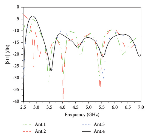
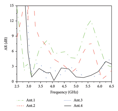
In order to reduce reflections at the terminations of the spiral arms, two shorting metal posts have been implemented between the ends of the spiral arms and the ground plane in Ant.2. The electric current flows down from antenna arms towards the ground with these shorted metallic posts, which can reduce the reflections at the arm terminations. As shown in Figure 4(b), the CP performance of the antenna has been improved from 4 GHz to 6.5 GHz. Due to the inductance introduced by the metal posts, the antenna impedance matching is also improved and thus achieving an impedance bandwidth of 69.2% (2.81 GHz–5.87 GHz). However, it should be noted that the 3-dB AR bandwidth is still narrow.
For achieving a good CP performance, two L-shaped metallic stubs are introduced between the ends of the antenna arms and the edge of the ground plane in the proposed Ant.3. The introduction of the L-shaped metallic stubs efficiently improves the CP bandwidth within the operation band, resulting in dual 3-dB AR bandwidths that cover 3.09 GHz–3.25 GHz and 3.55 GHz–6.12 GHz. The improvement of the CP bandwidth is due to the reduction of antenna current reflections at the terminations of the spiral arms.
We further proposed Ant.4 that utilized four stepped slots cut on the ground plane as an adjustment element to enhance the impedance matching and broaden the CP bandwidth. These stepped slots in Ant.4 significantly improve both the CP performance and impedance matching at lower frequencies (see Figure 4). It is worth noting that the L-shaped metallic stubs effectively reduce reflections at the termination of the spiral arms, and then, the implementation of four stepped slots on the ground plane offers additional means for fine-tuning the overall impedance matching and CP performance. Finally, the width of the L-shaped metallic stubs with w3 is configured to establish a connection between the arm of the spiral antenna and the ground plane. The impedance bandwidth of Ant.4 is more than 75.6% (3.16 GHz–7.0 GHz) after optimization. Moreover, Ant.4 features a broad 3-dB AR bandwidth of 66.2% (3.06 GHz–6.09 GHz).
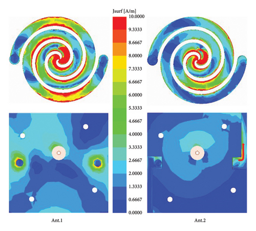
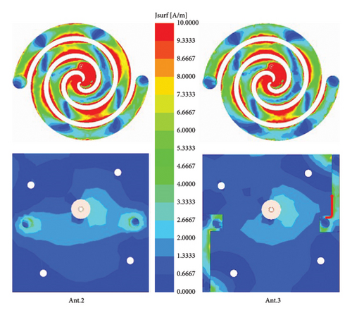
To investigate CP bandwidth improvements of the mechanism, the simulated current distributions on Ant.2 and Ant.3 are shown in Figure 5. For Ant.2, the electric currents from spiral arms flow toward the ground plane, concentrating around the posts. The focused currents initially flow towards the posts and then diffuse radially, disrupting the spiral current path and resulting in deterioration in the AR at lower frequency ranges. Additionally, two L-shaped metallic stubs are introduced to connect the ends of the spiral arms to the ground plane using two metal posts in Ant.3. The guided currents travel inward along the contours of the L-shaped metallic stubs, effectively extending the path of the traveling wave currents, as illustrated by the arrows in Figure 5. Similar simulated results are observed at various frequencies within this range. Therefore, the L-shaped metallic stubs not only reduce the reflection at the termination of the spiral arms but also participate in radiation. Consequently, by optimizing the parameters of the L-shaped metallic stubs, the final proposed antenna (Ant.4) achieves an ultrawide CP bandwidth. Meanwhile, the proposed antenna effectively generates right-handed CP waves due to the specific winding orientation of the spiral structure.
- I.
First, a compact planar spiral antenna with a square ground plane has been designed for the specified frequency. An integrated tapered microstrip line serving as an impedance transformer is employed to feed the spiral antenna. The design processes for this spiral antenna are similar to those described in reference [26].
- II.
Second, based on the structure described in the first step, two metallic posts are employed to link the arms of the spiral antenna to the ground plane. This connection serves to efficiently minimize reflections at the termination of the spiral arms.
- III.
Third, two L-shaped metallic stubs are introduced on the ground plane to connect the ends of the spiral arms with the two metal posts. The spiral antenna directs the current inward via the L-shaped metallic stubs, effectively prolonging the path of the traveling wave currents. This strategy can successfully increase the CP bandwidth.
- IV.
Finally, four stepped slots are cut on four corners of the ground plane, contributing to the optimization of the overall impedance and CP bandwidth of the antenna furtherly.
3.2. Parametric Study
The performance of the antenna is significantly affected by the L-shaped metallic stubs, as previously discussed design processes. CP bandwidth and impedance can be improved by adjusting the L-shaped metallic stubs and stepped slots. As a result, the key parameters have been studied.
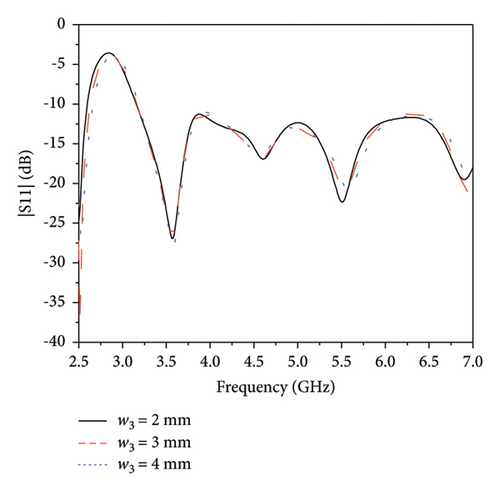
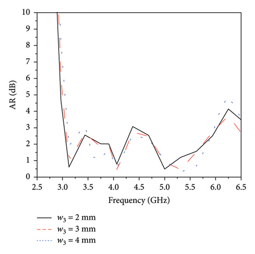
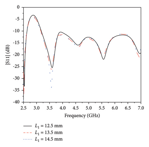
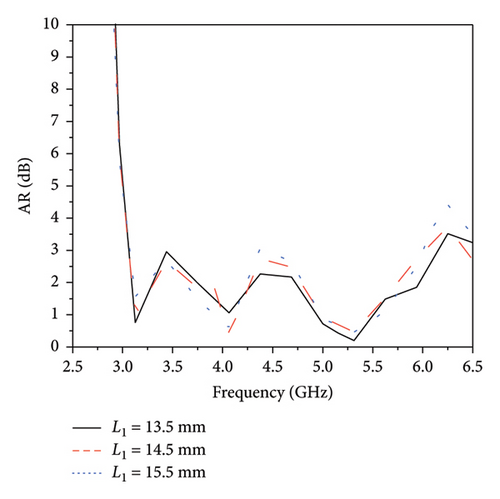
First, the optimal widths and lengths of the L-shaped metallic stubs are investigated. All other variables are fixed when one parameter is analyzed. Figure 6 demonstrates the reflection coefficients and ARs with different values of w3. It can be seen that the CP performance is improved in the range from 4 GHz to 5.5 GHz as w3 is increased from 2 mm to 4 mm and the impedance bandwidths of the antenna remain stable. By setting parameters w3 to 3 mm, a wider CP bandwidth can be achieved. Figure 7 presents the simulated results of the proposed antenna with different lengths of L1. There is an enhancement in the AR performance between 3.5 GHz and 4 GHz as L1 increases from 13.5 mm to 15.5 mm. However, it should be noted that the AR performance decreases from 4 GHz to 5.5 GHz within this range. To balance the CP performance across these two frequency bands, L1 is set to 14.5 mm, which allows for achieving a broader 3 dB AR bandwidth. These investigations show that the AR bandwidth is significantly influenced by both w3 and L1. As a consequence, adjusting these parameters can significantly increase the AR bandwidth within the operational frequency range.
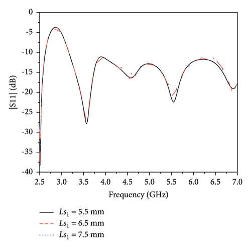
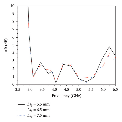
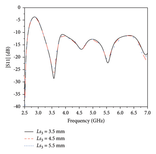
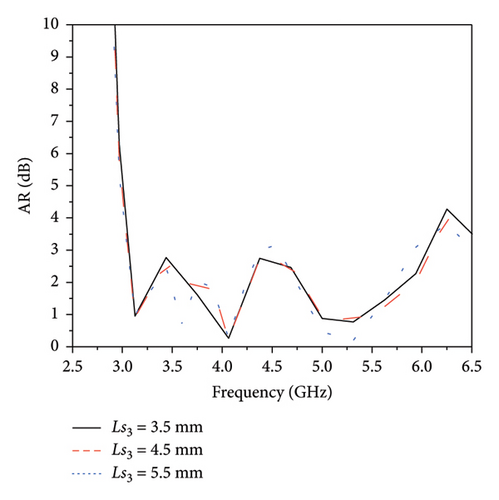
In addition, we further investigated the dimensions of stepped slots on the ground plane of proposed antenna. Figures 8 and 9 display the variations in impedance and AR bandwidth of the antenna corresponding to different Ls1 and Ls3, respectively. For different Ls1 and Ls3, the impedance bandwidth of the proposed antenna remains nearly constant. When Ls1 is increased from 5.5 mm to 7.5 mm, the AR at 4.5 GHz is deteriorated, and the AR in the lower frequency band remains constant. While the increase of Ls3 from 3.5 mm to 4.5 mm leads to degradation in AR at 4.5 GHz, it concurrently enhances the AR performance in the lower frequency band. It can be observed that adjusting Ls1 and Ls3 can enhance the AR bandwidth of the proposed antenna, while the impact on the impedance bandwidth is negligible. Therefore, the dimensions of the L-shaped metallic stubs and stepped slots are the critical parameters to optimize the overall CP bandwidth of the proposed antenna.
4. Experimental Results and Discussion
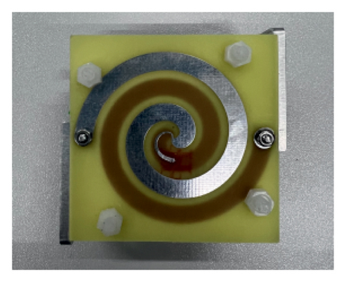
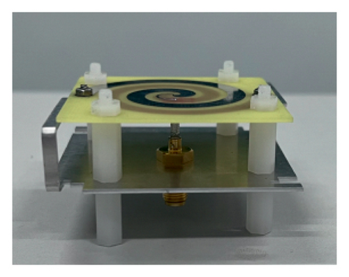
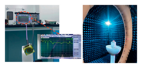
A prototype of the CP antenna has been fabricated and experimentally characterized to validate the design. Figure 10 exhibits the fabricated prototype and the measurement environment. Four Teflon supports are used to assemble the antenna. Two L-shaped metallic stubs and the ground plane are both made of aluminum. By adding two L-shaped metallic stubs to the sides of the ground plane, the size of the spiral antenna remains unchanged. Thus, the proposed antenna is compact and has a low-profile configuration. As shown in Figure 10(c), reflection coefficients, actual gain, AR, efficiency, and radiation patterns are measured by using a Rohde & Schwarz ZNB8 network analyzer and an anechoic chamber.
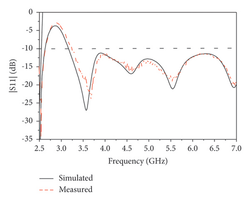
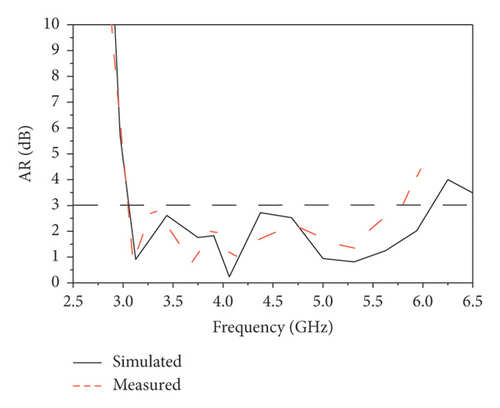
The simulated and measured reflection coefficients and ARs of the proposed antenna are shown in Figures 11(a) and 11(b), respectively. The measured impedance bandwidth for |S11| < −10 dB is more than 73.7% (3.23 GHz–≥ 7.0 GHz), which is consistent with the simulated value of 75.6% (3.16 GHz–≥ 7.0 GHz). The measured 3-dB AR bandwidth is from 3.05 GHz to 5.8 GHz (62.1%), corresponding to the simulated value of 3.06–6.09 GHz (66.2%). Both the measured results are in close agreement with the simulated results.

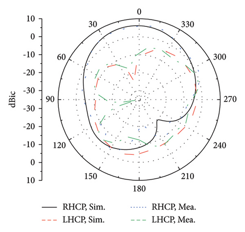
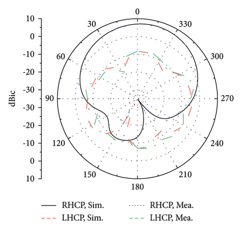
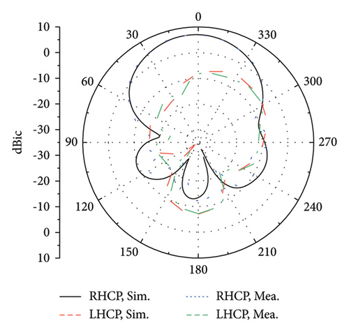
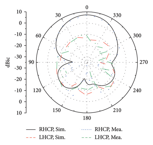
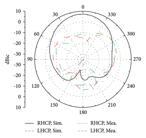
The measured gain, total efficiency, and radiation pattern of the antenna are consistent with the simulated results. As shown in Figure 11(c), the proposed antenna maintains a stable gain consistently above 6 dBic and reaches a peak gain of 7.4 dBic on the overlapping bandwidth (|S11| ≤ −10 dB, AR ≤ 3 dB). The slight variances observed between the gains obtained from simulations and actual measurements could be due to the imprecise dielectric constant of the substrate or flaws encountered during the manufacturing process. Within the overlapping bandwidth, both the simulated and measured total efficiency exceed 75%. Figure 12 illustrates the radiation patterns of the proposed antenna in the XOZ and YOZ planes at 3.5 GHz, 4.5 GHz, and 5.5 GHz, including the simulated and measured results for each frequency. Stable broadside radiation patterns have been consistently produced by the antenna on the operating frequency band, with measured half-power beamwidths of 72°, 62°, and 63° at 3.5 GHz, 4.5 GHz, and 5.5 GHz, respectively. In the boresight direction, the cross-polarization (LHCP) is over 15 dB lower than the copolarization (RHCP) at these three frequencies. Moreover, the measured front-to-back ratio at 4.5 GHz can be as high as 19 dB, indicating that the proposed antenna has a low back radiation and a high gain.

As mentioned above, the proposed spiral antenna with a ground plane exhibits good directional radiation characteristics. By introducing two L-shaped metallic stubs and four stepped slots on the ground plane, the impedance and 3-dB AR bandwidth of the spiral antenna are improved without increasing the overall dimensions. Table 2 summarizes a comprehensive comparison of the proposed antenna with those previously reported. In comparison to the several directional wideband CP antennas documented in existing literature, our proposed antenna exhibits a broader ARBW and a more compact structure. As demonstrated in [16], a cavity-backed circular radiating aperture is utilized to enhance the impedance and circular polarization bandwidths; however, this led to an increase in the overall size and complexity of the structure. The Vivaldi element as a radiator can enhance the CP bandwidth [17]. Both the cross dipole with a vacant-quarter ring and the asymmetric crossed bowtie dipole with a cavity are able to improve the AR bandwidth [21, 22]. But the sizes of these antennas are larger than our proposed antenna. The curved antenna arms and the curved tapered slots have a wide CP bandwidth, but they have relatively high profiles in [24, 25]. The proposed antenna achieves an overlapping bandwidth of 56.9%, which greatly exceeds what has been reported in previous literature. Additionally, the overall dimensions offer a notable benefit. Although employing smaller radiators leads to the peak gain deceasing of our design, this indicates that our design methodology is much more suitable for enhancing the CP bandwidth while maintaining a compact structure in directional spiral antennas.
| Reference | Impedance bandwidth (|S11|<−10 dB), % | AR bandwidth (AR ≤ 3 dB), % | Overlapping bandwidth (|S11| ≤ −10 dB, AR ≤ 3 dB), % | Size () | Peak gain (dBic) | Radiator structure | Complexity | Number of feed ports |
|---|---|---|---|---|---|---|---|---|
| [16] | 9.8–≥13 GHz, 28.0 | 9.80–12.70 GHz, 26 | 9.80–12.70 GHz, 26 | 0.98 × 0.98 × 0.33 | 8.5 | Cavity-backed aperture | Complex | Single |
| [17] | 3.06–5.52 GHz, 57.3 | 3.45–5.25 GHz, 41.4 | 3.45–5.25 GHz, 41.4 | 0.77 × 0.77 × 0.41 | 10.0 | Vivaldi antenna structure | Complex | Single |
| [21] | 1.77–3.19 GHz, 57.0 | 2.05–3.45 GHz, 51.0 | 2.05–3.19 GHz, 43.5 | 0.75 × 0.75 × 0.20 | 9.6 | Crossed bowtie dipole | Simple | Single |
| [22] | 3.14–6.34 GHz, 67.5 | 3.83–6.62 GHz, 53.4 | 3.83–6.34 GHz, 49.3 | 0.83 × 0.83 × 0.20 | 10.6 | Crossed dipole with an asymmetrical cross-loop | Simple | Single |
| [24] | 3.4–6.5 GHz, 62.6 | 4.00–6.15 GHz, 42.0 | 4.00–6.15 GHz, 42.0 | 1.20 × 1.20 × 0.24 | 10.0 | Inverted-S shared metal strip | Medium | Single |
| [25] | 4.26–7.23 GHz, 52.0 | 3.95–5.80 GHz, 38.0 | 4.26–5.80 GHz, 30.6 | 1.07 × 1.07 × 0.30 | 8.6 | Curved slot | Simple | Single |
| Proposed | 3.23–≥7 GHz, 73.7 | 3.05–5.80 GHz, 62.1 | 3.23–5.80 GHz, 56.9 | 0.59 × 0.59 × 0.17 | 7.4 | Planar spiral | Simple | Single |
- Note: All λg are calculated according to the lowest frequency of the antenna.
5. Conclusion
In this study, a compact planar spiral antenna with ultrawide bandwidth and directional radiation pattern is presented. Through the incorporation of two L-shaped metallic stubs on the ground plane, the path of the traveling wave current is efficiently elongated, and thus notably improves the CP performance without increasing the physical dimensions of antenna. After that, four stepped slots are additionally added on the ground plane to further enhance the impedance and CP bandwidth of the proposed antenna. The measurement results indicate that the proposed antenna has an impedance bandwidth greater than 73.7% and a 3-dB AR bandwidth of 62.1%. The proposed antenna maintains a stable gain consistently above 6 dBic and reaches a peak gain of 7.4 dBic on the overlapping bandwidth (|S11| ≤ −10 dB, AR ≤ 3 dB). The prototype can generate RHCP throughout the AR bandwidth. Hence, the proposed antenna is well-suited for UWB positioning applications.
Conflicts of Interest
The authors declare no conflicts of interest.
Funding
This work was supported by the special projects in key fields of ordinary universities in Guangdong Province under Grant 2021ZDZX4111, in part by Guangdong General Universities Young Innovative Talents Project under Grants 2023KQNCX245 and 2023KQNCX247, partially supported by the science and technology development plans in key areas of Guangzhou 2022 Major Research Project under Grant 202206070001, and the National Key R&D Program of China under Grant 2022YFB3604500.
Open Research
Data Availability Statement
The data used to support the fndings of this study are available from the corresponding author upon reasonable request.


