Continuous-Variable Pairwise Entanglement Based on Optoelectromechanical System
Abstract
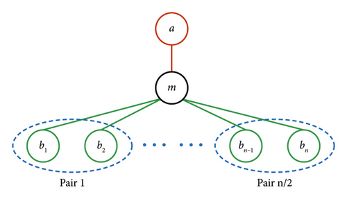
We show how to generate stationary continuous-variable pairwise entanglement between microwave modes in a hybrid optoelectromechanical system, which consists of a single Fabry–Pérot cavity, a parallel-plate capacitor with a moving element as the mechanical resonator, and several pairs of microwave cavities. The optical mode and mechanical resonator are coupled via radiation pressure; meanwhile, several pairs of the microwave mode and mechanical resonator are capacitively coupled. Under an experimentally reachable parameter regime, we show the influence of different key parameters on pairwise entanglement and find that it is also robust against temperature. Our model and results are expected to provide a new perspective on quantum networks with increasingly large scales, quantum internet with multiple local users, and multiport microwave quantum illumination radar.
1. Introduction
The quantum network lies at the heart of currently developed quantum technologies [1–15]. It would become increasingly mature when it became possible to integrate various modules into a single hybrid device and build networks based on these hybrid devices. As it is foreseeable that an ideal future quantum network may have multiple local users simultaneously, it is necessary to generate quantum entanglement between local units or nodes that are usually operating at microwave range and enable this kind of multipartite node to interface with other remote nodes.
Pairwise measures of correlations and mutual information are widely used to characterize the interactions within classical networks, which are key ingredients of widespread techniques such as principal component analysis and functional networks for their greatly simplified descriptions of complex systems [16]. In particular, the concept of pairwise is also utilized to study the properties of multiqubit entanglement generation [17].
Inspired by pairwise networks in the discrete-variable regime for quantum many-body systems [18–20], in this work, we propose a scheme to generate pairwise entanglement between microwave mode in a continuous-variable (CV) regime based on an optoelectromechanical system [21–40], which has the potential to be utilized in quantum technologies with large scale in the CV regime. For instance, this model can be used in multiuser quantum networks, where local users can share the microwave pairwise entanglement locally, and the optical part is capable of connecting a remote quantum “base station” with well-developed fiber optic technology [1–3]. Moreover, such pairwise entanglement is also expected to be useful in short-range quantum illumination radar [39–41] for all-around noninvasive biomedical scanning due to multipair entangled microwave modes corresponding to multiple parallel data received and other applications in the CV regime [42–49].
This paper is organized as follows. Section 2 shows the physical model of the system, with its quantum Langevin equations for describing the dynamics of the system and their linearization. In Section 3, we will derive the correlation matrix of the quantum fluctuations of the system in order to obtain the logarithmic negativity, which is considered the entanglement measure in this work. As the microwave-to-optical conversion mediated by a mechanical resonator is well investigated both from a theoretical and experimental perspective [29–31], in this work, we mainly focus on the pairwise entanglement between microwave modes. Therefore, we analyze the influence of some key parameters on CV microwave pairwise entanglement in Section 4, and Section 5 is for the conclusion.
2. Model
3. Correlation Matrix of the System and Quantification of CV Pairwise Entanglement
4. Results
As the microwave-to-optical conversion mediated by a mechanical resonator has been well investigated in recent years [29–31], in this section, we mainly focus on the CV pairwise entanglement between microwave modes. All results satisfy the Routh–Hurwitz criterion described in Appendix A unless specifically stated, which guarantees the steady state of the system. The parameter regime is a feasible extension over previous experimental works [23, 27, 28, 38] for the optical part, driving laser wavelength λ0c = 1550 nm, damping rate κc/2π = 2.8 MHz, driving power Pc = −68 dBm, vacuum optomechanical coupling G0c/2π = 125 kHz, and optical effective detuning Δc = 0.5 ωm. For mechanical resonator, resonant frequency ωm/2π = 2.8 MHz and damping rate κm/2π = 10 Hz. For the microwave part, the parameters of two MCs in each pair are almost the same except for effective detuning Δwj for satisfying the Routh–Hurwitz criterion. These two detunings are opposite Δw1 = −Δw2, and every newly added microwave pair should follow this criterion. Under this condition, the other parameter between distinct microwave pairs can be different, which will not affect the stability of the system. For simplicity, we choose all microwave pairs with the same parameters except the resonant frequency of each MC at first. The parameters for MCs read: damping rates κw/2π = 170 kHz, input power Pw = −68 dBm, the vacuum electromechanical coupling G0w = [ωw/(2π × 12.13)] · 510 kHz with capacitor gap d≈ 30 nm [27, 28] and the unit of ωw is GHz. The effective microwave detunings are defined as Δw ≡ Δw1 = −Δw2 = ⋅⋅⋅ = Δw(n − 1) = −Δwn. For each MC pair, the detunings of two MCs have the same absolute value but opposite signs. In the following, we label the MC resonant at 9 GHz with positive or negative detuning as 9+ or 9−. Other unmentioned parameters are shown below each figure.
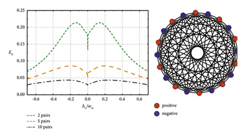
In Figure 2, we mainly focus on the influence of the microwave pair number on the entanglement, so we make all MCs have the same resonance frequency at 9 GHz. In this case, there are four MCs with their detunings Δw ≡ Δw1 = −Δw2 = Δw3 = −Δw4, where MCs with detunings Δw1 and Δw2 are regarded as a pair, so does for Δw3 and Δw4. For simplification of expression, we define Δw1 and Δw3 as the positive detuning and Δw2 and Δw4 as the negative detuning in the MC pairs. We find that the entanglement only exists between two MCs whose detunings are opposite. Also, one can notice that these entanglement curves have a dip at the point Δw = 0. This is because at this point all the microwave cavities are on-resonance, and the pair designation becomes arbitrary. Under this condition, two arbitrarily picked microwave cavities can get entangled. Back to pair number’s influence on the pairwise entanglement, the pairwise entanglement declines as the MC pairs are added. It can be phenomenologically thought that, as the scale of the system increases, the correlation between the subsystems deceases. Under this kind of structural design and parameter setting, we can further explore the maximum network size where CV entanglement still exists or is useful. We find that the pairwise entanglement will not be zero but will approach zero when we add microwave pairs. So in theory, we can consider that, under this kind of structural design and parameter setting, one can continuously generate such pairwise entanglement in the system with a larger size as long as the experimental conditions allow.
Then, we turn to study the condition where various microwave pairs resonate at different frequency ranges. For simplicity, we choose the 3-pair system, in which the first MC pair resonates at 9 GHz, 37.5 GHz for the second, and 60 GHz for the third. In principle, modes with any resonant frequency in the microwave band can get entangled in our system, which is beneficial for fulfilling the requirements of broadband working in quantum networks and the Internet. From Figure 3, we can know that the higher the frequency of two microwave modes, the larger the entanglement between them can be achieved. It happens in part because higher-frequency microwave photon contains more energy, which leads to stronger robustness in the thermal noise environment. We also notice that the entanglement between 37.5+ and 60− is virtually the same compared with the trace of 37.5− and 60+, as it is for other pairs. The reason why there is a little asymmetry is because of the asymmetrical parameter settings, i.e., the frequencies of two entangled microwave modes are not identical.

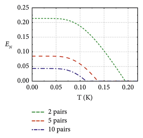
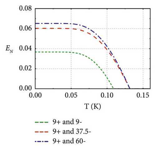
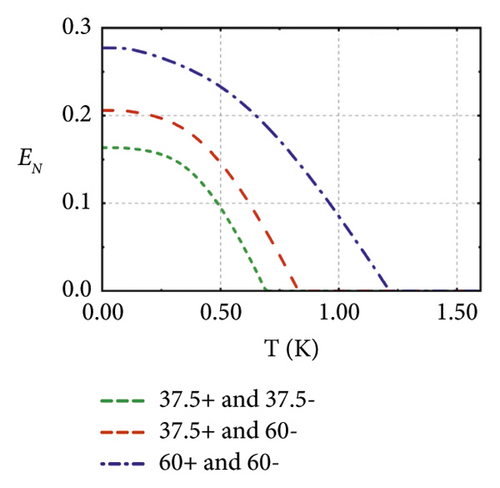
Based on the two models described above, we further investigate the relation between pairwise entanglement and temperature. As shown in Figure 4(a), we find that the pairwise entanglement still survives above 100 mK in a system containing 10 MC pairs. The entanglement in more scalable systems shows lower resistance in the thermal environment. In Figures 4(b) and 4(c), we find that the entanglement between higher-frequency microwave modes is larger and can show stronger thermal robustness. Both of them correspond to the above statement.
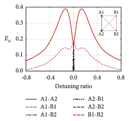
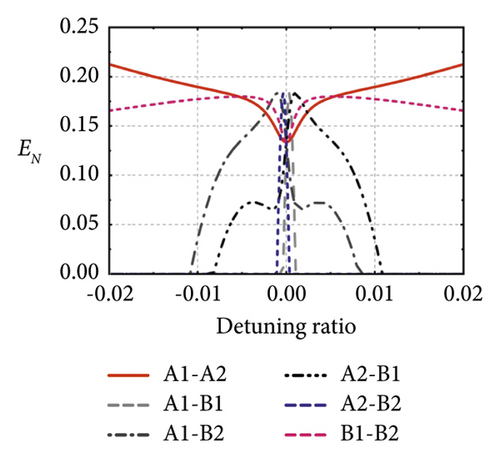

From Figure 3, we have already known that the detuning of two entangled microwave modes in such a pairwise system should have opposite signs. Next, we study the influence of the absolute value of detuning on such entanglement. From Figure 4(d), we find that the pairwise entanglement merely exists between two MCs whose detunings have the same absolute values and opposite signs. As shown in Figure 4(e), an enlarged plot of Figure 4(d) around the zero-detuning point, the entanglement of other combinations only appears near the zero-detuning point, where all MCs are truly identical, so that the pair designation becomes arbitrary, and this is why all traces will intersect at a zero-detuning point. In Figure 4(f), the 2-pair system described in Figure 2 with identical absolute value detunings, we find that the entanglement will not exist in a wide detuning range between two MCs with the same absolute value detunings and same signs. Therefore, we can conclude that the detunings of two entangled MCs should have opposite signs and identical absolute values when wide-range detuned. Furthermore, using this feature, we can make an entanglement switch that can turn on or off the entanglement between MCs by changing the detunings of each MC.
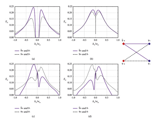
In real experimental implementations, there will always be some variation in the parameters. So we analyze the impact of detuning deviation of a single MC Δd = Δw1 − Δw on pairwise entanglement in Figure 5, this analysis method is also applicable to multipair MC deviating conditions. The model studied is the 2-pair system described in Figure 2, except that a detuning deviation Δd is exerted on one MC named . From Figure 5(a), if Δd = 2π × 50 kHz, the system will be unstable near the zero-detuning region, which makes the pairwise entanglement vanish, while the pairwise entanglement can still be generated in other stable regions. If we try to maintain the stability of the system in all detuning range, the detuning deviation Δd = 2π × 4 kHz can meet our needs, as shown in Figure 5(b). Beyond the near-zero region, systems operating at different detuning points have different sensitivities to detuning deviations. As shown in Figures 5(c) and 5(d), the effective detuning of is 0.91 Δw and 1.1 Δw corresponding to Δd = −0.09Δw and 0.1 Δw, the system is still able to maintain its stability all over the detuning range. When Δd = −0.1Δw and 0.11 Δw, there would be unstable region that exists near the detuning Δw = 0. With the absolute value of detuning deviation Δd increasing, the unstable region would expand. Therefore, once Δd exceeds about ±10 percent of Δw, the system will be unstable near the purple dip shown in figures and the pairwise entanglement will vanish there. Under this condition, other stable regions can still generate stable pairwise entanglement the same as mentioned above.
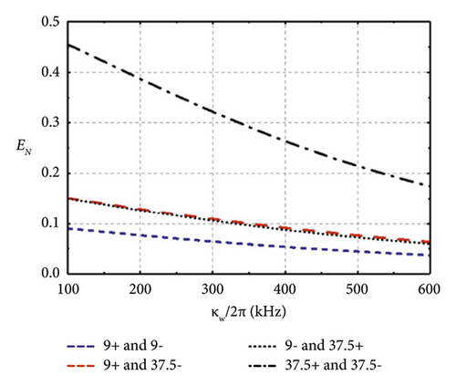
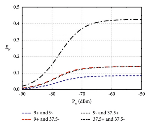
The influence of the damping rate of MC κw and input microwave power Pw on entanglement is shown in Figure 6. Intuitively, the higher damping rate of each MC may reduce the pairwise entanglement. When the input power is lower than −70 dBm, an increase in input power can enlarge the entanglement and the approximate maximum entanglement is obtained around −60 dBm, which could be realized by state-of-the-art engineering cryogenic setups [56].
As we can know from Figure 7, the wavelength of input driving laser has just a little impact on the pairwise entanglement of two microwave modes both resonate at 9 GHz. Only when the normalized optical detuning is positive, the system will reach a steady state and is capable to generate stationary microwave pairwise entanglement, and its maximum is obtained ranging from Δm to 2 Δm based on this model.

From the results shown above, we can summarize four discoveries of CV microwave pairwise entanglement based on our model. At first, as the scalability of the system increases, in other words, more MC pairs in the system, the microwave pairwise entanglement decreases. Secondly, higher-frequency microwave modes can get better entangled and more resistant in the thermal noise environment. Thirdly, the detunings of two entangled MCs should have opposite signs and near-absolute values. In order to reach the steady-state entanglement in all detuning range, the detuning deviation between two MCs is not supposed to exceed a particular range depending on the specific cases, for example, 10 percent in a 2-pair system. The last one, the smaller the damping rate of each MC, the better pairwise entanglement can be obtained, so does for the input power in a certain range.
Our proposal is the first report to generate CV pairwise entanglement based on the experimentally feasible parameters. As for the experimental realization, the mechanical resonator could be manifested as a parallel-plate capacitor with a moving element. The stationary plate is divided into several evenly sized sections corresponds to the number of microwave cavities, each connected to an inductor to build the capacitively electromechanical coupling with microwave cavities, while the moving plate forms an end mirror in a Fabry–Pérot cavity to interact with optical mode via radiation pressure. The interaction picture can be represented as that the optical cavity is used for driving the mechanical element motion to generate pairwise entanglement between microwave cavities. As for the comparison with other similar works, in our model the entanglement can still exceed the value of 0.2. This is on the same order of magnitude as previous theoretical work using the same measure of entanglement, allowing one to achieve higher fidelity of teleportation than can only be achieved using classical methods [24, 33–35]. We also believe that these results will be beneficial to design and control CV pairwise entanglement based on optoelectromechanical systems.
5. Conclusion and Outlook
In conclusion, we have studied the CV microwave pairwise entanglement based on a hybrid optoelectromechanical system. We have analyzed the influence of several key parameters, such as the MC pair number, microwave resonant frequency, ambient temperature, and detuning deviation of each MC, on CV pairwise entanglement. Such a model may play important role in various rapid-developing quantum technologies with the trend that the platforms of quantum technologies are getting increasingly scalable and integrated, like quantum Internet [1–3] and quantum short-range radars [39–41]. For example, the prototype microwave quantum illumination radar described in reference [41] uses two entangled microwave radiation (one pair) to enhance the performance of detecting a 1 m apart target, in which the signal mode is used to detect targets and the idler mode is reserved locally waiting for the returned signal for homodyne measurement. However, if we want to detect targets from all directions at the same time, one pair of microwave modes may not enough, and the effect of the traditional radar’s rotating scanning method on such a quantum system is still not thoroughly studied. Our model can simultaneously generate multiple pairs of entangled microwave modes that can obtain multiple sets of parallel data of targets, which has the potential to solve this problem. Besides, our model could be further used to the case that multiple pairs of optical modes simultaneously pump and resonant in the optical cavity. In this condition, the multiple pairs of microwave-optical pairwise entanglement with broadband can be generated, which has wide-ranging implications in hybrid quantum networks in the context of communication, sensing, and computing.
Disclosure
An arXiv has previously been published [57].
Conflicts of Interest
The authors declare that they have no conflicts of interest.
Acknowledgments
This work was supported by the National Key Research and Development Program of China (Grant nos. 2018YFA0307400 and 2018YFA0306102), Sichuan Science and Technology Program (Grant nos. 2021YFSY0063, 2021YFSY0062, 2021YFSY0064, 2021YFSY0065, 2021YFSY0066, 2022YFSY0061, 2022YFSY0062, and 2022YFSY0063), National Natural Science Foundation of China (Grant nos.U19A2076 and 62005039), and Innovation Program for Quantum Science and Technology (Grant no. 2021ZD0301702).
Appendix
A. Drift Matrix and Calculation of Logarithmic Negativity
Open Research
Data Availability
The data that support the findings of this study are available from the corresponding author upon reasonable request.


