Cascaded Control System Design for Quadrotor UAV through Relay with Embedded Integrator-Based Automatic Tuning Approach
Abstract
Due to their enormous characteristics and applicability, quadrotor unmanned aerial vehicles (UAVs) have enjoyed much popularity lately. However, designing a stable control strategy for quadrotors still remains one of the major concerns mainly due to the requirement of an accurate system model. They are naturally underactuated systems, with complex and nonlinear dynamics as well as interaxes couplings. Considering the dynamical complexities of these vehicles, one of the efficient methods is to utilize the relay feedback experiments and automatic tuning approach to tackle these issues. This paper investigates the employment of the relay with embedded integrator approach, wherein the quadrotor dynamics are estimated effectively with minimal parameters as compared to previously utilized relay with hysteresis technique. Frequency sampling filter (FSF) is further utilized for the extraction of the needful data through the signals obtained using the relay experiments, followed by the estimation of the plant dynamics. PID controllers have then been developed using the approximated quadrotor models. Which are used in the proposed cascade control structure for the quadrotor. The demonstrated results and analysis present the efficacy of designed control system technique for the quadrotor UAV.
1. Introduction
Multirotor UAVs are regarded as one of the most revolutionary inventions in the present era [1, 2]. They have enjoyed a great attention and applicability in a vast variety of applications lately [3, 4], as they offer numerous characteristics such as controllability, maneuverability, simple design, economy, and vertical take-off and landing (VTOL) capability [5, 6]. Quadrotor UAVs have turned out to be the most popular out of all the available multirotor configurations [7]. Consequently, quadrotor UAVs are extensively explored over the past three decades in order to advance them mainly in terms of configuration, modelling, and control [8–11]. Quadrotor UAVs are considered as an underactuated system as they offer four control inputs to control the six degrees of freedom [12]. The complex nonlinearities and interchannel couplings are also the issues that require attention when designing the control system for these rotorcrafts [5, 13]. Additionally, when operated outdoor, quadrotors are susceptible to atmospheric turbulences [14, 15]. As well, during the indoor operation, the airflow of the propellers reflected from the shelters and walls also causes the external disturbance [16]. Furthermore, when multiple multircopters operate in the closer proximity to one another, the downwash from one another also causes an impact over the flight performance. Therefore, considering these attributes of the quadrotors, design of the stable and robust control system has been considered as the most challenging task.
The cascade control structure technique is proposed in this paper to realize the control system solutions for the quadrotor UAV, wherein PID controllers have been used in the cascaded control loop. Several control strategies have been designed for the multirotor UAVs over the years, such as [17–21]. PID controllers are supposed to be the most vastly utilized controllers in the quadrotor control system because of their simplified structure and ease of practical implementation [22, 23]. Due to these reasons, presently the majority of the mainstream commercial autopilot flight controllers are using PID controllers as their main control algorithm, i.e., micropilot [24], ardupilot [25], paparazzi autopilot [26], AfroFlight Naze32, and Multiwii SE V2.0. During the design of the control algorithm for the quadrotor, appropriate tuning of the parameters of respective controllers has been one of the most challenging tasks. The quadrotor dynamics are defined through a set of nonlinear equation [27]. It would be a very complex to design the controller for quadrotor through conventional methods that utilize dynamic model of the plant. Furthermore, these physical parameters of the quadrotor are usually determined with the help of certain experimentation, which in turn is supposed to be difficult and time-consuming. Also, these parameters may vary as per operating conditions [28]. Additionally, in the quadrotor’s physical model, dynamics for the sensor and actuator are often neglected. Also, the quadrotor model is mostly linearized to simplify the designing process of the controller that is performed at the cost of loss of few dynamical details [29]. Hence, taking into account, all the aforementioned hitches, the PID controllers designed through model-based design approach do not necessarily ensure the desired quadrotor control performance.
An alternate method has been proposed in this paper in which the dynamics of UAVs are estimated using response data obtained experimentally from the multirotor through relay feedback system. Relay with hysteresis mechanism is used previously for this purpose in [30, 31], wherein two parameters are required to execute the required mechanism such as hysteresis and relay amplitude. The hysteresis parameter is mainly required for the filtration of noisy signal. The relay with an embedded integrator method has been proposed in this paper. One of the major features of the relay with an integrator approach is the simplification of the identification of the dynamics that otherwise need the information of the complex and higher-order models [32]. The major theme of opting for the relay with embedded integrator approach is to make sure that the determined information of the plant is encompassed within medium and lower range of frequencies. Moreover, the effect of high-frequency measurement noise is minimized due to the presence of the embedded integrator, and the need to use a hysteresis for the noise is reduced.
- (1)
Robust and stable control solution has been featured for the quadrotor UAV through the automatically tuned cascade control algorithm
- (2)
PID controllers have been designed through the automatic tuning approach that is based on the relay with the embedded integrator technique and system identification. Which incorporates all of the actual quadrotor dynamics that include actuators, sensor dynamics, and gyroscopics
2. Dynamic Model of Quadrotor and Control Architecture
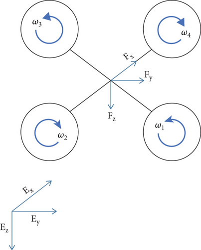
In this equation, εm and rwv denote the motor’s constant for time and steady-state gain, respectively.
2.1. Control System Structure
Quadrotor is termed as an underactuated system that additionally offers coupled dynamics and nonlinearities. Also, the strong coupling among multiple input-output channels is supposed to be challenging when designing the control system for the quadrotors. The controlled variables in the quadrotor system are three torques to provide angular position control, whereas the altitude control is performed through force (f). The stable and robust tracing of the desired signals such as ϕ∗, θ∗, and ψ∗ is used to be the main objective of the quadrotor control system as well as to tackle any unwanted disturbances.
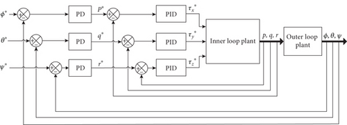
Cascaded control system using PID controllers has been proposed in this paper to feature the control solution to the aforementioned problems associated with the quadrotor. In the cascaded control structure, the multirotor system dynamics are decomposed in the several simpler and smaller subsystems. For which, a separate PID controller is tuned for each of the decomposed subsystem totally based upon the concerned subsystem dynamics. Which in turn provides the effective resolution towards the control issues of the systems, which exhibit complexity in the dynamics [34]. The attitude control system is supposed to be the heart of the quadrotor control structure as it is responsible to maintain the desired 3D orientation of the unmanned vehicle [35]. For the quadrotor cascaded control design, dynamics of the attitude system are broken down as inner loop that deals with angular rate and outer loop that deals with angular position. The proposed structure of the quadrotor cascaded attitude control system is depicted in Figure 2. In the inner loop control system, PID controllers attain the angular rate control. While in the outer loop, PD controllers are utilized to provide the control algorithm for the angular position of the quadrotor. Due to the existence of an integrator already in the system dynamics of the outer loop, as presented in Equation (2), the integral term from the PID has not been employed in the outer loop control system. Consequently, the addition of an integral controller in the control system of outer loop would lead to the oscillatory response.
3. Estimation of the System Dynamics and Controller Design
3.1. Relay with Embedded Integrator
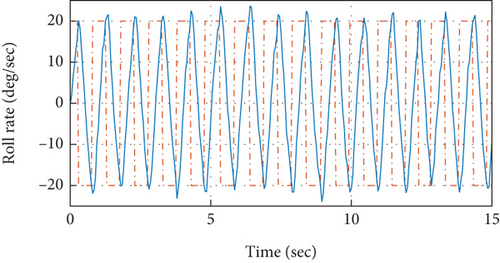
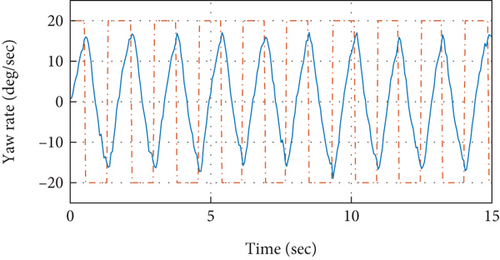
The setup of the relay feedback experiment with the embedded integrator is presented in Figure 3.

The incorporation of the integrator into the relay process is actually from the perspective of the identification of the system fundamental frequency (ω1). This type of relay feedback system provides fundamental frequency that intersects the imaginary axis when observing the frequency response at the Nyquist plot. The relay embedded with an integrator leads to the fundamental frequency that exhibits larger time period. This helps the user to negate the hectic process of selecting the appropriate hysteresis parameter in the relay with hysteresis experiments. Also, the system’s frequency response is held into the lower and medium range of frequencies that subsequently prevent the signal from high-frequency noises.
3.2. Frequency Response Analysis
The objective of frequency response analysis is to analyze the data obtained through relay feedback experiments and to extract the information from that data. Which leads to estimation of the dynamics of the related model. Both input and output signals acquired through the relay experiments are analyzed as periodic in nature. Therefore, FSF would be effective to use for the extraction of the useful data from the set of both periodic input and periodic output signals [36, 37].
q−1 in this expressions represents back shift operator that is formulated as q−1x(k) = x(k − 1).
3.3. PID Controller Design
The inner loop plant of the quadrotor exhibits the dynamics that are faster. Hence, to achieve the quicker closed-loop response, a comparatively low-performance factor would be required. Hence, it is chosen to be β = 2. Accordingly, the PID parameters for the inner loop (roll rate) control system have been determined through (30)–(32) as Kc = 1.566, τI = 2.0281, and τD = 0.1018, whereas, for the yaw rate control, the PID controller values are determined as Kc = 8.170, τI = 1.031, and τD = 0.051.

For the cascade control algorithm, to achieve closed-loop stability and robustness, it is required for the outer loops to possess the response time much slower than the subsequent inner loops for the robust and stable cascade control system [32]. Therefore, the outer loop time constant is chosen to be twice of the delay time, and β is opted as 4. In this way, the PID controller’s outer loop parameters are calculated as Kc = 1.566, τI = 2.028, and τD = 0.101 for the roll attitude axis. Similarly, values for the PID controllers to be used for the yaw attitude axis are obtained as Kc = 1.028, τI = 3.089, and τD = 0.155.
4. Validation
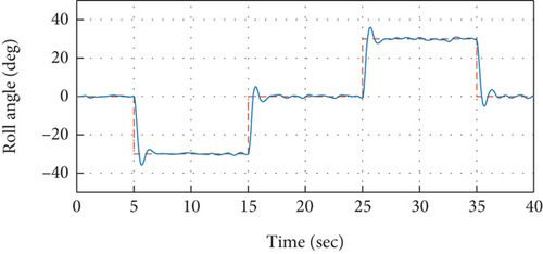
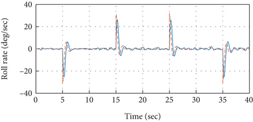
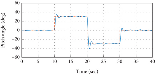
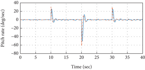
To validate the proposed idea, the PID controllers tuned and designed based on the relay with integrator mechanism are implemented over the quadrotor model under simulation environment. The model specifications of the quadrotor are presented in Table 1. The control system is implemented in the cascaded structure as presented in Figure 2. Atmospheric turbulences that are modeled based on the Dryden turbulence model [41] are injected into the model of the system as well that are demonstrated in [34, 42]. The attitude control performance to track desired roll axis is presented in Figure 7. It is observed from the measured roll angular response that the reference command for the roll axis has been traced efficiently without exhibiting any steady-state error. While the stable response of the quadrotor for the roll angular rate to achieve the required roll angle has been presented in Figure 8, it can further be observed that the control signals produced by outer control loops serve as reference signal for the related inner loop, as also depicted in Figure 8. Therefore, the set point command for roll angular rate in Figure 8 depicts the response of control system from the outer loop. In the similar approach, the efficacy of the designed and implemented control system for the remaining attitude axes such as pitch and yaw has also been analyzed in Figures 9-11–12.
| Parameter | Value |
|---|---|
| Ixx | 3.4 × 10⁻⁴ kgm2 |
| Iyy | 3.4 × 10⁻⁴ kgm2 |
| Izz | 4.5 × 10⁻⁴ kgm2 |
| α | 9.5 × 10⁻⁷ |
| kd | 2.4 × 10⁻⁹ |
| r | 0.3 m |
| εms | 70 ms |
| rwv | 1 |
| m | 0.7 kg |
| g | 9.8 m/s2 |
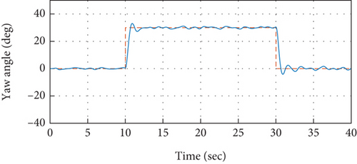
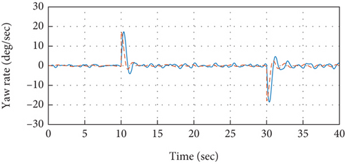
Moreover, comparison is performed in order to examine the superiority of the presented relay with embedded integrator-based automatic tuning approach over the conventional model-based PID controller design approach that is presented in [34]. The model-based PID controller is designed for the roll attitude system and is implemented over the quadrotor system. The comparison analysis is presented in Figure 13. It has been analyzed in the demonstrated results that the control performance of the relay-based autotuned control system provides superior attitude response compared to the model-based control system. An improved overall time response including both transient as well steady-state performance is experienced by the autotuned PID control system. Especially when implemented experimentally, the autotuned control system would prove to be even superior over its conventional counterpart control system. Due to the fact that it incorporates almost all of the actual dynamics of the quadrotor including sensors, actuators, and gyroscopics.
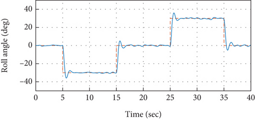
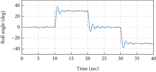
It is evident from the analysis of the demonstrated results that the proposed control system, based on cascaded PID control mechanism that has been tuned via the automatic tuning method based on the relay with integrator technique, is providing the required attitude performance with efficacy through keeping a better overall time response of the system including both transient and steady-state responses, since it exhibits minimal overshoots and is providing control operations at an improved rise and settling time.
5. Conclusions
A robust and stable control design approach for the quadrotor UAV has been presented. Cascaded control structure has been proposed to offer the control solutions to the dynamically complex underactuated quadrotor system. PID controllers for the each cascaded control structure stage are designed through the automatic tuning approach. Wherein the automatic tuning approach is based on the actual data acquired through the relay with an embedded integrator approach. The major theme of opting for the relay with embedded integrator approach is to make sure that the determined information of the plant is encompassed within the low and medium range of frequencies. Moreover, the effect of the measurement noise associated with the high frequencies is minimized due to the presence of the embedded integrator, and the need to use a hysteresis for the noise is reduced. The proposed cascaded PID control system designed through relay with an integrator-based automatic tuning approach is implemented over the actual quadrotor model. The results and observations demonstrated in this paper suggest that the designed control strategy is able to achieve the robust and stable attitude performance with an improved transient and steady state response.
Conflicts of Interest
The authors declare that they have no conflicts of interest.
Acknowledgments
This research is funded by the Researchers Supporting Project Number (RSPD2023R947), King Saud University, Riyadh, Saudi Arabia.
Open Research
Data Availability
Data used to support the findings of this study are included within the article.


