GPS-SBAS-Based Orbit Determination for Low Earth Orbiting Satellites
Abstract
A space-based augmentation system (SBAS) provides real-time GNSS correction signals via geostationary satellites for near-ground GNSS users. To use the SBAS correction for low Earth orbit (LEO) satellites, the correction, especially the ionosphere correction, must be adjusted for the LEO altitude. We apply modified SBAS data to LEO satellite onboard navigator to improve the positioning accuracy of a LEO satellite for possible real-time use. The onboard navigator requires high positioning reliability, and code pseudoranges, rather than phase pseudoranges, are used for the primary measurements. The Galileo NeQuick G model is used to determine the real-time conversion factor of the SBAS ionosphere correction for a LEO satellite. The GPS L1 data from GRACE satellite are combined with the SBAS data from the ground receiver. The onboard navigator combines the precise satellite dynamic model with an extended Kalman filter to improve positioning accuracy and stability. The kinematic positioning method, which uses the weighted least square method without the dynamic model, is also performed for comparison. The SBAS correction reduces the positioning error in both the kinematic positioning and the dynamic positioning. The positioning error reduction of the GPS and WAAS case over the GPS-only case is 25.2% for the kinematic method and 30.6% for the dynamic method. In the case of the dynamic method with the SBAS corrections, the positioning error remains smaller than that of the GPS-only dynamic method even after the satellite has left the SBAS service area.
1. Introduction
The global navigation satellite system (GNSS) can serve as a navigation sensor of low Earth orbit (LEO) satellites. The positioning accuracy of GNSS navigation is constrained by the accuracy of the ephemeris and clock information provided by the GNSS satellites. Low-cost single frequency receivers are also limited by the ionospheric signal delay. For real-time GNSS positing, ground GNSS users can use the real-time service (RTS) by the international GNSS services (IGS), which provides GNSS satellite orbit and clock corrections via the Internet. However, using an Internet connection makes it difficult to use in outer space.
A space-based augmentation system (SBAS) provides real-time correction data via geostationary satellites. The correction data includes GNSS satellite orbits, clock, and ionospheric delay information. The correction data are transmitted using standard GNSS radio frequency signals; no additional data links or hardware is required except SBAS signal decoding software. The SBAS also provides integrity information to monitor positioning accuracy. The integrity function detects anomalous increases in positioning errors, which happened intermittently in GNSS receivers, by statistical methods, and generates a warning signal for SBAS users. The integrity information is also used to calculate measurement weights for weighted least square positioning. As ground GNSS users, LEO satellites can receive SBAS signals if they carry GNSS receivers with SBAS support. Then, the accuracy of the LEO satellite GNSS positioning can be improved by the SBAS corrections.
SBAS was originally developed for aircraft navigation with global positioning system (GPS) L1 code pseudorange receivers, and some modifications are needed for LEO satellite applications [1]. The ionospheric delay is the most notable difference between the ground and LEO applications due to different ionosphere path lengths. SBAS provides the ionospheric delay correction as a two-dimensional ionosphere map, which is a gridded data set and whose value represents a signal delay of the ground GNSS receiver. Therefore, SBAS ionospheric delay correction cannot be used directly for LEO satellites.
One of the ways to convert the SBAS ionosphere correction for the LEO satellite is to use a scaling factor, which scales down the original ionospheric delay values according to LEO satellite’s altitude. A series of studies has been performed on the use of the ground-based ionospheric model in LEO satellites. Montenbruck and Gill [2] proposed a scale factor which is the ratio of the ionospheric delay at the ground and LEO. They used the Chapman profile to calculate the electron density of the international reference ionosphere (IRI) model. Kim and Lee [3] and J. Kim and M. Kim [4] demonstrated its usefulness. Those studies used a constant scale factor determined by comparing postprocessed IGS ionosphere map data with space observed LEO global positioning system (GPS) data. This constant scale factor is unable to represent the variation of the scale factor along with time, location, ionosphere activity, etc. J. Kim and M. Kim [5] have proposed a scale factor derived from the Galileo NeQuick G ionosphere model for real-time use. NeQuick is a 3D ionosphere model, and the receiver’s position can be either in the ground or in space. Therefore, it can be directly used for LEO satellite. The ionosphere scale factor can be obtained by dividing the ionospheric delay observed at LEO altitude by the delay observed on ground. Galileo provides NeQuick G model parameters via its navigation message, and the NeQuick G model is continuously updated. J. Kim and M. Kim [4] showed that the scaled SBAS ionosphere correction outperforms the NeQuick ionosphere model calculated for LEO satellite.
Some studies have been done on the use of SBAS orbit and clock corrections for LEO satellite orbit determination. Kim and Lee [3] first proposed the use of SBAS correction for LEO satellite positioning and performed a feasibility study by comparing scaled SBAS ionosphere correction with dual frequency ionosphere observations. J. Kim and M. Kim [4] applied SBAS orbit, clock, and ionosphere corrections to determine the position of the LEO satellite. A constant scale factor was used with a kinematic (weighted least square) positioning method. J. Kim and M. Kim [5] improved the ionosphere correction accuracy by applying the variable scale factor driven by NeQuick G model. The same kinematic positioning method was applied. These SBAS-LEO studies focused on the use of SBAS corrections for satellite onboard navigator.
A satellite GNSS positioning filter can be designed for two different purposes: onboard navigator and scientific mission. As to the aircraft application, the onboard navigator requires high positioning reliability rather than high positioning accuracy. The scientific mission, on the other hand, emphasizes on positioning accuracy. The use of phase measurements provides better positioning accuracy but requires a bias fixing algorithm which may converge on a relatively long time. For this reason, the code pseudoranges remain as the primary measurements of the onboard navigator.
SBAS was designed for aircraft, and the SBAS signal was designed to augment code pseudorange positioning. SBAS integrity information is used not only to provide protection levels but also to combine SBAS-corrected pseudoranges. The protection level provides a bound on the position error with a probability derived from the SBAS integrity requirement [1]. There have been some studies on the use of precise orbit and clock corrections for LEO satellite Precise Point Positioning (PPP) applications. Hauschild et al. [6] studied the application of orbit and clock corrections from GEO satellite to LEO satellites. Allahvirdi-Zadeh et al. [7, 8] studied on the application of QZSS MADOCA orbit and clock corrections from QZSS satellite to LEO satellites. These LEO-PPP experiments applied precise orbit and clock data to phase measurements for PPP applications. Allahvirdi-Zadeh et al. also applied simulated SBAS orbit and clock corrections for the LEO-PPP experiments, but the SBAS integrity information was not applied. Since the SBAS orbit and clock corrections must be used with SBAS pseudorange weight information, which is calculated for the SBAS integrity information, using the SBAS orbit and clock corrections alone (without the weight information) provides less performance than the PPP orbit and clock corrections.
Satellite position can be predicted with high accuracy by using accurate dynamic models, e.g., gravity and radiation pressure. Therefore, it is more effective to combine the satellite dynamic model into a positioning method. A Kalman filter is generally used to combine GNSS measurements with the dynamic models, rather than the kinematic weighted least square filter. The dynamic model is used to propagate the satellite position and velocity to the next measurement epoch, and the GNSS measurement is used to update or adjust the satellite status. This dynamic method improves the accuracy and stability of LEO positioning. The satellite position can be determined even if fewer than four satellite signals are available. Many of onboard LEO GNSS receivers have the dynamic model Kalman filter for real-time use.
We have developed a dynamic model-based positioning filter for LEO satellite with the enhancement of SBAS corrections. Satellite dynamic model is combined with extended Kalman filter to process GPS code pseudorange measurements. SBAS orbit and clock corrections are applied, and the ionosphere correction is adjusted using the NeQuick-derived variable scale factor. Preliminary studies by the authors [4, 5] used the kinematic positioning method without the dynamic models. SBAS was originally developed for real-time aircraft use by using the kinematic positioning method with code pseudorange measurements. Implementing the dynamic model with the SBAS corrections in the positioning filter makes it useful for LEO satellite onboard navigator.
2. Space-Based Augmentation System
SBAS is an augmentation system that generates GNSS corrections and transmits the information to users via geostationary orbit (GEO) satellites. SBAS also generates integrity information for GNSS signal monitoring. GNSS signals received by multiple ground monitoring stations are transmitted to the master station, and SBAS corrections are generated by processing them. The generated SBAS information is uplinked to the GEO satellite and then transmitted to the user. SBAS service area is determined by the distribution of the SBAS ground monitoring stations.
SBAS correction is classified into several message types (MT). MT is defined from 0 to 63, but only part of it is currently used. The SBAS message includes the corrections for the GPS orbit and clock error and ionospheric delay and integrity information. Long-term correction includes orbit and long-period clock correction, and fast correction includes short-period clock correction [1, 9]. Long-term correction is transmitted at intervals of more than 90 seconds in MT 25, and fast correction is transmitted at intervals of 6-8 seconds in MT 2-4. Ionospheric correction is transmitted every 5 minutes or more, and information is transmitted for each grid point at a latitude/longitude interval of 5 degrees. In MT 18, ionospheric grid point (IGP) mask, which is a factor related to the availability of IGP information, is transmitted. Ionospheric correction and its covariance are transmitted in MT 26. A detailed method for calculating SBAS corrections is described in RTCA document [1].
3. SBAS Corrections for Low Earth Orbiting Satellites
SBAS has been developed for aircraft navigation and ground applications. Therefore, it cannot be used immediately in the LEO environment. The main difference between the terrestrial and LEO is the signal delay due to the ionosphere and troposphere. Troposphere delay is due to hydrostatic and wet air in the troposphere below the altitude of 60 km. Since the LEO satellite altitude is mainly above 300 km, it is not affected by the troposphere. Since the SBAS provides no troposphere corrections, the SBAS user must instead use mathematical troposphere model. LEO satellite users can ignore the troposphere delay.
In the above equation, UT is the current time in hours, λ is the longitude, ϕ is the latitude, and h is the altitude. After generating the bottom side (below the peak of the F2-layer) and the top side (above the F2-layer peak) model using these inputs, the electron density in the path between the user and the satellite is numerically integrated to obtain the slant ionospheric delay.
For LEO satellites, the troposphere term is deleted. The effect of receiver noise and multipath should be determined by analyzing the signal of the receiver mounted on the satellite, but we used the equation provided by the RTCA [1]. For aircraft nonprecision approach, m2.
4. Dynamic Model
An extended Kalman filter (EKF) was combined with a precise dynamic model for LEO orbit determination. If the kinematic weighted least square (WLS) method is used for LEO orbit determination, the orbit cannot be estimated if the number of observations is less than four. On the other hand, if the EKF is used in combination with the dynamic model, it has an advantage that the orbit can be estimated even if there are less than four observations. In this case, the position of the LEO satellite, computed from the precise dynamic model, can be used for the propagation process of the EKF. Our precise dynamic model includes Earth’s gravitational field, third body perturbation, relativity, drag, and solar radiation pressure. The data used in each model are summarized in Table 1.
| Force model | |
|---|---|
| Earth gravity | GGM03C (50 × 50) |
| N-body | JPL DE 421 |
| Solid Earth tides | IERS 2003 conventions |
| Ocean tides | IERS 2003 conventions |
| Relativity | IERS 2003 conventions |
| Atmospheric drag | Jacchia 1976 model |
| Solar radiation | Canon-ball model |
| Reference frame | |
| Conventional inertial reference frame | J2000.0 |
| Precession and nutation | IAU 1976 |
| Earth orientation | IERS C-04 |
| Estimation parameters | |
| Satellite position and velocity | Earth-centered inertial |
| Satellite clock offset | |
| Atmospheric drag coefficient | |
| Solar radiation coefficient | |
| Empirical accelerations | Radial, transverse, normal |
GRACE GGM03C model was used as the Earth’s gravitational field. The degree and order up to 50 were used using spherical harmonic expansion. IERS 2003 convention formula was used to model the solid Earth tide and ocean tide. Atmospheric drag used the U. S. standard atmosphere (USSA) density model, which has a low computational cost. Both the drag and solar radiation pressure models were implemented as a simple canon-ball model, but atmospheric drag coefficient and solar radiation coefficient were adjusted during the estimation process. For the acceleration calculated from each model, the orbit and velocity of the LEO satellite were calculated by numerical integration using the Runge-Kutta 7-8th-order algorithm. For the coordinate transform between the Earth centered inertial and the Earth centered Earth fixed coordinates, a precise transformation model was implemented, which included the precession, nutation, polar motion, and Earth rotation. All models used for the coordinate transformation are also summarized in Table 1.
5. Orbit Determination Process
The state transition matrix of the EKF is driven from the partial derivative of the force model, as shown in Table 1, with respect to the state variables. To save computational time, the state transition matrix has been simplified compared to the full force model; the luni-solar perturbations, solid Earth tide, and ocean tide are neglected. The gravitational harmonics are only considered up to the second order zonal J2. A detailed description of the EKF filter algorithm can be found in [11]. A simple positioning fault detection algorithm was applied. If the difference between the final position estimates and the position calculated by the dynamic model was greater than the threshold, the orbit calculated by the dynamic model was considered to be the current position. The threshold value was set to 2 m, which was the 2σ value of the 3D orbit estimation error.
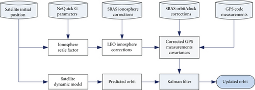
Figure 1 shows the navigation filter procedure. For the processing of measurement data, the first process is to determine the ionosphere scale factor using the NeQuick G model. The next step is to convert the SBAS ionosphere correction with the scale factor, and the GPS code pseudorange measurement is corrected with the scaled ionosphere correction [5]. Before the SBAS corrections were applied, the GPS measurements went through an receiver autonomous integrity monitoring (RAIM) process to isolate bad measurements. The SBAS orbit and clock corrections are applied to compute the nominal pseudorange. The difference between the measured range and the nominal range is applied to the EKF. The propagated orbit with the satellite dynamic model is adjusted with the measurement. The update interval of the estimation states in Eq. (7) corresponds to the measurement interval of the GPS measurements, 10 s. The position and velocity of the satellite’s orbit are propagated with the satellite dynamic model for 10 s.
6. Data Processing
Since there are currently no LEO GNSS receivers capable of receiving SBAS signals, the GNSS receiver data from a LEO satellite was combined with SBAS data received on the ground to simulate a LEO GNSS receiver with SBAS signals. SBAS correction is transmitted by GEO satellites, and there is no difference between ground received SBAS signal and LEO received SBAS signal. This research used the actual GPS observation data of the GRACE satellite and the SBAS data received from the CNES ground stations. The GPS and SBAS data were processed from September 22 to October 21, 2015. The GRACE GPS data interval is 10 s.
The GRACE satellites were developed by NASA/DLR and launched in 2002 as a twin low-orbit satellite to measure the Earth’s gravitational field [12]. At an initial altitude of about 480 km, it flew in a polar orbit with an inclination of 89.5° and was decommissioned in 2017. Each GRACE satellite carries a high precision BlackJack GPS receiver, which provides dual frequency code and phase data [13]. GRACE Level-1B data provided by JPL were used, and the GPS data is corrected for clock offset and has an interval of 10 s. The precise GRACE orbit estimated by JPL was used as a truth orbit to calculate the orbit estimation error.
SBAS data provided by Centre National d’Etudes Spatiales (CNES) was used. This research used WAAS PRN 135 and EGNOS PRN 120 data. SBAS information was applied to the GPS data where both the fast/long-term and the ionospheric correction were available. In other words, SBAS mode was enabled when the GRACE satellite was in the SBAS service area. SBAS integrity information was used for the determination of the range measurement weight but was not used for the protection level calculation [1].
Figure 2 shows the ionospheric grid points of WAAS and EGNOS. The grid interval is 5° at the middle latitude and 10° at the high latitude. SBAS service area represents the location where the SBAS ionospheric correction data is available and corresponds to the ionospheric grid points. The service area is determined by the geographical location of SBAS ground monitoring stations. The WAAS and EGNOS service areas overlap in the North Atlantic. In the overlap area, the WAAS corrections were used because the accuracy of the WAAS ionospheric correction is usually better than the EGNOS ionospheric corrections.
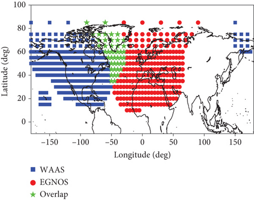
Table 2 summarizes the case numbering used according to the positioning method and SBAS type. Labels 1 and 2 represent the kinematic positioning and dynamic positioning method, respectively. Labels a through d represent the type of SBAS correction used. For comparison, no SBAS correction (GPS only) cases were included. For example, case 1a represents the kinematic positioning using only GPS data. Cases 1b and 1c represent the kinematic positioning with WAAS and EGNOS corrections. Label d represent combined used of WAAS and EGNOS correction data.
| SBAS signals | GPS only | GPS+WAAS | GPS+EGNOS | GPS+WAAS+EGNOS |
|---|---|---|---|---|
| Kinematic positioning | Case 1a | Case 1b | Case 1c | Case 1d |
| Dynamic positioning | Case 2a | Case 2b | Case 2c | Case 2d |
7. Orbit Determination Results
The WAAS and EGNOS data were processed to correct GRACE GPS measurements, and their orbit determination accuracy was compared with GPS-only accuracy. The dynamic model-based orbit determination results were compared with the kinematic orbit determination results.
To convert the SBAS ionosphere correction for LEO satellites, the ionosphere scale factor was first calculated using the NeQuick G model. Figure 3 shows the variation of the scale factor on September 28, 2015. The peak value of the scale factor appeared a total of 16 times, and the period is the same as the orbit period of the GRACE satellite. The peak occurred when the LEO satellite flew at low latitudes around 2 p.m. local time (LT). This peak time corresponds to the peak time of the ionospheric delay. Smaller peaks occurred when the satellite was in the night zone. The average value of the scale factor is 0.452, which means that the ionospheric delay observed in the GRACE altitude is 45.2% of the delay observed on the ground.
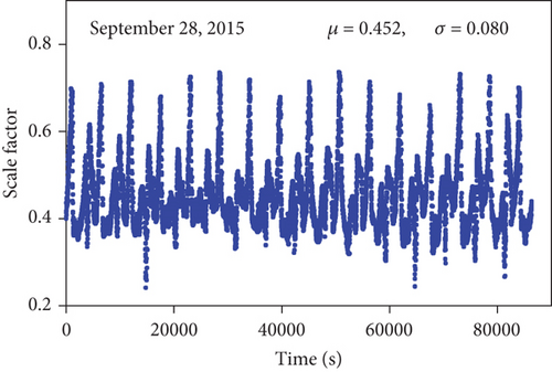
Figure 4 shows the variation of the SBAS corrections for the GPS PRN7 signal when the GRACE-B satellite is in the WAAS service area. At that time, the satellite flew for 15 minutes in the WAAS area. Long-term correction represents the norm of X, Y, and Z position corrections. The scaled ionosphere correction for LEO altitude is compared with the raw ionosphere correction for ground. The fast and long-term corrections showed no significant variation, but the ionosphere correction showed a large variation. It is because the ionospheric delay is highly correlated with latitude.
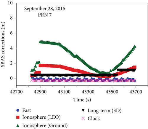
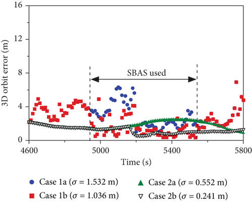
Figure 5 shows the GRACE satellite orbit errors with the WAAS corrections. The GPS-only cases (1a, 1b) are presented for comparison. The WAAS correction was available for 10 minutes. The GRACE satellite entered the WAAS service area at 4950 s and departed at 5550 s. In case of the kinematic positioning, cases 1a and 1b, the orbit error reduction by the WAAS is obvious in the WAAS service area. The orbit error is reduced by 32.4% in the service area. The dynamic positioning, cases 2a and 2b, shows different behavior. The orbit error reduction by the SBAS is not significant until 5170 s, which is 200 s after entering the service area. Instead of the slow error reduction, the error reduction goes through 5750 s, which is 200 s after departing the service area. This is because the accuracy of the EKF filter depends on the accuracy of the past. The orbit error reduction from case 2a to case 2b is 56.3%.
Figures 6 and 7 show the 3D orbit determination error of GRACE satellite when each SBAS was used within the SBAS service area on September 27, 2015. For comparison, positioning errors are also shown with GPS observations only. Since GRACE satellites do not always fly in the SBAS region, the x-axis is indicated as a measurement index rather than time. There are large time gaps between SBAS service area, and it is better to use the measurement number instead of measurement time for better visibility. The availability of WAAS and EGNOS corrections is 12.5% and 6.0%, respectively. The reason for the low availability of EGNOS correction is that the EGNOS ionosphere correction accuracy degrades significantly near the service boundary. Authors’ experiments show that it is better not to use the EGNOS correction when the grid ionospheric vertical error (GIVE) index is greater than 12. In other words, EGNOS correction use area is smaller than its service area. In the case of using the kinematic method, the deviation of the positioning error was large in all epochs. In contrast, the positioning error of the dynamic method was very smooth because the positioning follows the orbit driven by dynamic modeling. Orbit error increased during the daytime when the ionosphere activity was large and decreased during the nighttime. In the case of the kinematic method, the standard deviation is reduced by 37.7% when WAAS corrections (cases 1a vs. 1b) were applied and reduced by 22.6% when EGNOS corrections (cases 1a vs. 1c) were applied.
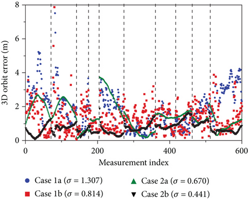
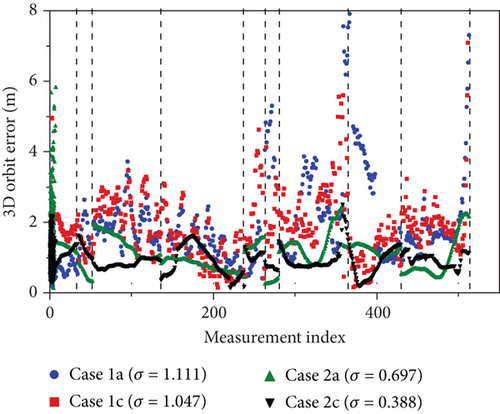
Figure 8 shows the RMS errors of GRACE orbit position estimates from September 22 to October 21, 2015. Figures 7(a) and 7(b) are the kinematic method results, and Figures 7(c) and 7(d) are the dynamic method results. Figures 7(a) and 7(c) are the GPS-only results, and Figures 7(b) and 7(d) are the GPS with WAAS and EGNOS results. In the overlap area of WAAS and EGNOS, WAAS corrections were used. The white line indicates the boundary of the service area of WAAS and EGNOS. The EGNOS area used in this study is smaller than the EGNOS service area. The boundary line of EGNOS indicates the location where the availability of the ionospheric correction is 50%. This availability value was chosen after a series of experiments for the best orbit accuracy with the EGNOS corrections.
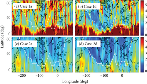
The large error of the kinematic method at the low latitude (cases 1a and 1d) is due to the large ionospheric delay near the geomagnetic equator. The dynamic method (cases 2a and 2d) shows much smaller error at the same low latitude. The total error level of the dynamic method is smaller than that of the kinematic method. The error reduction by the SBAS correction is evident for both the kinematic and dynamic methods. The RMS orbit error is reduced by 0.725 m (25.2%) with the kinematic method and reduced by 0.608 m (30.6%) with the dynamic method. Although the dynamic method reduces the overall orbit determination error, the SBAS correction is still effective to reduce the orbit error.
Table 3 shows the GRACE orbit determination error statistics in each flight direction. The orbit error statistics are only computed in the SBAS service area. Compared to cases 1a and 2a, the error STD of the cases 1d and 2d are smaller in the R and T directions. The error STD in the R direction, which is similar to the signal path of the GRACE satellite, is greatly reduced. This is because the SBAS clock and ionospheric corrections affect the reduction of the orbital error in the R direction. In case of the mean value of the RMS error, the reduction is mixed. Some cases even show some increase with SBAS corrections. Unmodelled bias component in the SBAS corrections may be the cause of the error mean value increase. In cases 2a and 2d, compared to the GPS-only cases 1a and 1d, the STD of the orbit errors are reduced by 22% (for WAAS) and 6.5% (for EGNOS). As with the kinematic method, the error was greatly reduced in the R and T directions.
| Case 1a | Case 1d | Case 2a | Case 2d | |||||
|---|---|---|---|---|---|---|---|---|
| Mean | STD | Mean | STD | Mean | STD | Mean | STD | |
| R (m) | 0.555 | 2.565 | 1.171 | 1.646 | 0.037 | 1.194 | 0.111 | 1.017 |
| T (m) | -0.057 | 1.256 | 0.032 | 0.942 | 0.054 | 0.984 | 0.255 | 0.742 |
| N (m) | 0.203 | 1.035 | 0.187 | 0.839 | 0.171 | 0.572 | 0.030 | 0.625 |
The WAAS and EGNOS service areas cover a small portion of the entire Earth. However, there are other SBAS that work or test: Japanese MSAS, Indian GAGAN, Russian SDCM, and South Korean KASS. And several SBASs are under development or planned: Chinese BDSBAS, African A-SBAS, and Australia and New Zealand’s SouthPAN. Therefore, the limited availability of the SBAS service for the LEO satellite will be reduced with the deployment of the new SBAS. In addition to the increasing SBAS coverage, the dynamic OD filter is effective outside SBAS coverage as shown in Figure 5.
8. Conclusions
SBAS data was applied to LEO satellite onboard navigator to improve the positioning accuracy of a LEO satellite for possible real-time use. The onboard navigator combined the precise satellite dynamic model with an extended Kalman filter for improved positioning accuracy and stability. One month’s worth of WAAS and EGNOS data was processed with some adjustments for LEO satellites, including the scaled ionospheric delay and associated error covariance. Galileo NeQuick G model was used to calculate the scale factor. The adjusted SBAS data was applied to the GPS data from a GRACE satellite when the satellite location is within the SBAS service area. The GPS code pseudorange measurements were processed, and the positioning accuracy of the GPS-only and GPS+SBAS was evaluated. To analyze the combined effect of the satellite dynamic model and the SBAS corrections, the kinematic positioning method, which uses the weighted least square method without the dynamic model, was performed for comparison. The SBAS correction reduces the positioning error in both the kinematic positioning and the dynamic positioning. The accuracy improvement over the GPS-only case was significant for both WAAS and EGNOS. When WAAS correction is used, the estimation error reduction of the 3D orbit is 25.2% for the kinematic method and 30.6% for the dynamic method. In the case of the dynamic method with the SBAS corrections, the positioning error remains smaller than that of the GPS-only dynamic method even after the satellite has left the SBAS service area.
Conflicts of Interest
The authors declare that they have no conflicts of interest.
Acknowledgments
This research was supported by the Space Core Technology Development Program funded by the Ministry of Science and ICT (NRF-2016M1A3A3A02016943).
Open Research
Data Availability
The data used to support the findings of this study are available from the authors upon request.


