Research on the Method of Ground Stress Balance under Complex Conditions Based on Geometric Tracing
Abstract
The accuracy of the initial ground stress balance determines the accuracy of the finite element analysis of geotechnical problems. The traditional ground stress balance method has a good balance effect for simple geotechnical models but has strong limitations when the structure and soil interact with each other, the geometry of the model is complex, or the constraints are complicated. To deal with such problems, this paper proposes a general ground stress balance method based on geometric tracing by iteratively superimposing the static displacement field of the numerical model with the initial node coordinates of the numerical model. Two commonly used methods as well as the proposed method were tested with a model which contains both soil elements and structural elements and a case study. Test results show that the proposed method is capable of dealing with a complex model in which the commonly used methods fail to. Furthermore, the proposed ground stress balance method was demonstrated to be clear and has rapid convergence and high accuracy for complex stratum-structure geotechnical problems.
1. Introduction
Ground stress is the natural stress that exists in the Earth’s crust undisturbed by engineering, also known as the geostatic stress, absolute stress or original rock, and soil stress, which is the fundamental force that causes the deformation and damage of underground engineering [1–4]. Therefore, in the numerical simulation process involving geotechnical materials, the ground stress balance should usually be performed on the finite element numerical model first. The purpose of ground stress balance is to find the ground stress field that can make the initial displacement field close to zero under the action of initial load and boundary conditions [5–7]. The accuracy of the ground stress balance process determines the accuracy of numerical simulation results.
The commonly used ground stress balance techniques include the automatic method, keyword definition method, ODB import method, and nodal force method. The pros and cons of each method are clear [8, 9]. Using these methods or their variants, scholars have conducted a lot of fundamental research. Wang et al. [10] proposed a method for stratum-structure geotechnical problems, which is applicable to the problems that have a contact feature. Zavriyan [11] derived a theoretical formulation for the initial stress of rod element in ground stress analysis. He et al. [12] and Xiao et al. [13] use the element birth and death technique to achieve ground stress balance in ABAQUS, which effectively alleviates the convergence difficulties of the ground stress balance problem. Xu [14] proposed a method by applying nodal loads directly to the finite element model. Guo [15] carried out a finite element analysis of the ground stress field process with stress concentration problem. Yu et al. [16] established a convenient superposition model that can be used to simulate the stress and displacement fields around cracks. Fu et al. [17], Zhang et al. [18], Xie et al. [19], and Meng et al. [20] performed regression inversion analysis of the ground stress field for different types of models. The above studies on the ground stress balance are mostly dealing with simple models, and the application of their methods is limited. When the interaction between structures and soil is involved or the constraints are complex, the existing methods often fail to work or have low accuracy [21].
To address the above-mentioned problem, this paper discards the conventional idea of adding a stress field to the model or applying nodal force to mesh nodes and proposes a more general method based on geometric tracing to quickly achieve ground stress balance for complex finite element models. The basic idea of this method is that the displacement field after the static analysis of the numerical model is superimposed with the initial node coordinates of the numerical model and reconstructed the model iteratively until it meets the citation, so as to achieve the purpose of setting the displacement field to zero. The proposed method can avoid the failure of ground stress balance due to the difficulties of too many structures and complex interactions in the model, since it only reconstructs the node coordinates and did not change the original stress field.
2. Analysis of Commonly Used Ground Stress Balance Methods
In ABAQUS, four types of ground stress balance methods are often used, including the automatic method, keyword definition method, ODB import method, and nodal force method. For the numerical model with few materials and simple boundary conditions, the calculation results of all four methods can meet the requirements. Among them, the results obtained by the automatic method are the most ideal and should be preferred when available [22]. In practical engineering, structures such as underground diaphragm walls or buildings coexisting with foundations are often involved and interact with the soil foundation. These problems can be collectively referred to as stratum-structure geotechnical problems [23], for which commonly used methods are often unable to converge or have poor balance results. [24].
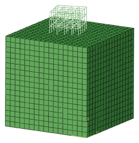
To demonstrate stratum-structure geotechnical problems, a ABAQUS model is established as shown in Figure 1. The basic size of the foundation is 50 m × 50 m × 50 m (X × Y × Z). The foundation material is clay. A concrete frame structure is set on the foundation. The foundation soil adopts the elastic-plasticity model using the Mohr-Coulomb yield criterion, while the concrete adopts the linear elasticity model. The material parameters are shown in Table 1. The frame structure is bound with the foundation using TIE constraints in ABAQUS, so that the upper surface of the foundation is fully coupled with the frame structure in all degrees of freedom (fully constrained displacement in x, y, and z directions). Normal displacement at the sides of the soil cube is constrained, while the bottom has pined. The automatic method and the ODB import method were used to perform the ground stress balance for the established model since these two methods have been proved to be the most effective and adaptive.
| Materials | Modulus of elasticity (kPa) | Poisson’s ratio | Cohesion (kPa) | Angle of friction (°) | Gravity load (kN/m3) |
|---|---|---|---|---|---|
| Clay | 1.5 × 10⁴ | 0.3 | 32 | 14 | 20 |
| Concrete | 3.15 × 10⁷ | 0.2 | — | — | 25 |
According to the test results, the automatic method fails to converge during the calculation because of the complexity of the model. Figures 2 and 3 show the calculation results of the ODB method in the static analysis stage and the ground stress balance stage, respectively. Figure 4 shows the relationship curve between the iteratively import times and the maximum absolute displacement.
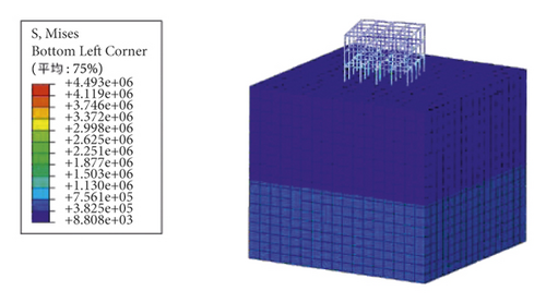
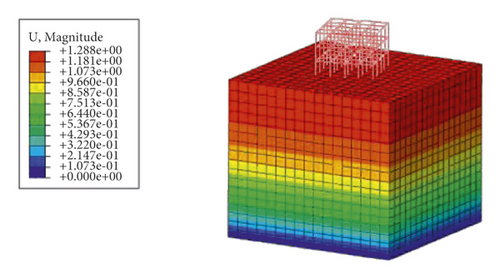
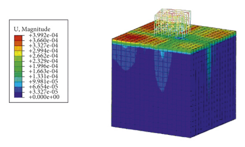
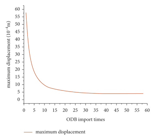
It can be seen from Figures 2 and 3 that the maximum absolute value of displacement of the result of the import method is 3.9 × 10⁻⁴ m, which is barely acceptable. But the stress results changed dramatically before and after the balance process. This happens because the concept of the ODB import method is to apply the initial load and boundary conditions to the model, obtain the stress field through static analysis, and import the obtained stress field into the ground stress balance process as the initial stress field with one or more iterations. This process may constantly alter the initial stress state of the model, which is contrary to the original purpose of ground stress balance and affects the accuracy of subsequent calculations of the model. From Figure 4, it can be seen that with the increase in the number of ODB import, the absolute value of the maximum displacement of the model decreases rapidly before 15 times, changes slowly afterwards, and tends to converge at 3.9 × 10⁻⁴ m at the 35th iteration. This phenomenon shows that the ODB import method may converge at a nonzero value of the maximum absolute value of displacement. After certain iteration times, the results may not become better afterwards, which makes the method very tedious and has strong limitations.
3. Ground Stress Balance Method Based on Geometric Tracing
3.1. Steps of the Proposed Method
When dealing with geotechnical engineering problems in ABAQUS, there are often cases where soil and structures exist at the same time and interact with each other, such as the foundation excavation deformation analysis, pile-soil interaction analysis, and simulation of tunneling under existing buildings [25]. For these so-called stratum-structure geotechnical problems, the existing commonly used ground stress balance methods may converge slowly or even unable to converge. Traditional methods usually use external loads or add stress fields to the numerical model in the ground stress balance process [15]. Therefore, they can handle simple problems because the stress field is simple and can converge easily. But when the model is complex, the stress field will be complex too, and convergence problem may take place.
-
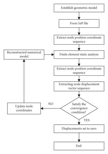
Step 1. Using ABAQUS to establish the geometric model of the engineering structure. Apply loads and boundary conditions to the numerical model. Then, run a static analysis to obtain the displacement field of the model. Meanwhile, record the initial position coordinates of all nodes as from the INP file of the numerical model.
(1)where is the position coordinates sequence of the the i-th node in j-th iteration of the reconstruction. , , and are the coordinate of x, y, and z, respectively. N is the total number of nodes in the numerical model. M is the total number of iterative reconstructions. -
Step 2. The displacement fields result from the static analysis of the numerical model, which is extracted to obtain the displacement vector sequences of all nodes in the numerical model. The expressions of the displacement vector sequences of all nodes in the numerical model are
(2)where is the displacement vector of the i-th node in j-th iteration of the reconstruction. , , and are the displacement vector sequence of x, y, and z, respectively. -
Step 3. Determine whether the maximum absolute value of the displacement of all nodes satisfies the preset convergence condition, if it does, the ground stress balance process stops and returns the stress field, and if not, proceed to step4. The maximum absolute value of the displacement of all nodes can be calculated by the following equation:
(3)where max(|Li j + Vi j − Li 0|) is the maximum absolute value of the displacement of all nodes in the numerical model after the j-th iteration of reconstruction of the numerical model. Li 0 is the vector of initial position coordinates of the i-th node in the numerical model. , , and are the i initial value of x, y, and z of the coordinates of node i. It is generally considered that when the order of stress before and after balance remains unchanged, and the soil displacement is below 10−4 m, the ground stress balance process can be considered acceptable and will not have an impact on the subsequent analysis. This is because the effective displacement caused by foundation excavation, and tunneling construction is usually above 10−3 m. Therefore, the preset convergence condition of this method is set to(4) -
Step 4. The displacement vector of all nodes in step 2 is then superimposed backwards with the corresponding node position coordinate in step1, using the following equation:
(5)where is the position coordinates sequence of the i-th node in j + 1-th iteration of the reconstruction. Vi j−1 is displacement vector of the i-th node in j – 1-th iteration of the reconstruction. -
After the superposition, the nodes of the numerical model are reconstructed to obtain a new numerical model. The static analysis of the reconstructed numerical model is carried out to obtain the displacement field of the reconstructed numerical model. Meanwhile, the loads and boundary conditions applied to the reconstructed numerical model were kept unchanged [5–7] for each iteration of the static analysis process.
-
Step 5. Repeat Step 4 until the maximum absolute value of the displacement of all nodes in the reconstructed numerical model satisfies the preset convergence condition. Then, the results of the last iteration were obtained as the result of the ground stress balance process.
-
It should be noted that the proposed method extracts the node coordinates and node displacements from the model INP file and the model result ODB file directly, forms the new node coordinates after backwards superposition, and then replaces the node coordinates in the INP file of the former model to generate the new model during iteration. Therefore, the accuracy of the ground stress balance process of the proposed method will not be affected regardless of the complexity of the boundary conditions or load conditions of the numerical model, and thus, the noncoverage or low efficacy problems were addressed.
-
Step 6. The final step is to set the displacement field of the result in Step 5 to zero so that the geotechnical engineering simulation can proceed. Figure 5 shows the flow chart of the proposed method.
3.2. Method Implementation
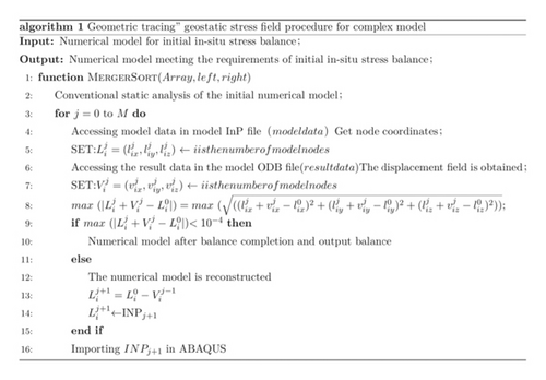
The proposed method is codified through the Python interface provided by ABAQUS, so that after the model is built, the Python script can be used to complete the ground stress balance process, which greatly improves the work efficiency. [26–28] In order to achieve the aforementioned ground stress balance, we first need to export the coordinates of each node of the initial numerical model by accessing the model data generated by ABAQUS, that is, the INP file. The ODB file of the first static analysis was accessed to record displacement field data of all nodes. Then, equation (4) will be calculated to determine whether the process stops. If the coverage citation is not met, the backwards superimpose will be carried out to form a new geometry model in ABAQUS and run the next round of iterations until the coverage citation is met.
The above calculation process is placed in a for loop statement that breaks only when (4) is satisfied. Thus, the ground stress balance process was carried out in an iterative way. Figure 6 shows the pseudocode of the algorithm [29].
4. Case Study
In the simulation of geotechnical engineering problems, there are often cases where soil and structures exist simultaneously and interact with each other, such as the analysis of foundation excavation [29], the pile-soil interaction simulation, and the tunneling construction under existing buildings [30], which usually contain complex soil layer forms and stratigraphic parameters. In order to verify the effectiveness and superiority of the proposed method, the ground stress balance process of the following simulation of the tunneling construction under the existing building will be carried out in ABAQUS.
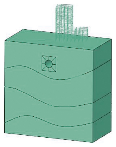
The geometry of the model is shown in Figure 7. The ideal elastoplastic model with Mohr-coulomb yield criterion and elastic model were used for the soil layers and the structure, respectively. The dimensions of the foundation model are 100 m × 50 m × 100 m. The soil foundation contains silty clay, silty sand, sandy soil, and moderately weathered sandstone from top to bottom. The diameter and thickness of the tunnel are 8 m and 0.15 m, respectively. The buried depth of the tunnel is 15 m. Above the foundation is a building that has a 15° angle with the tunnel direction. The building structure and foundation are bound by tie constraints. The bottom of the model is fully constrained (x, y, and z directions), while the normal displacement is constrained for four sides. The finite element model is shown in Figure 7, and the material parameters are shown in Table 2.
| Materials | Modulus of elasticity (kPa) | Poisson’s ratio | Cohesion | Angle of friction (°) | Gravity (kN/m3) |
|---|---|---|---|---|---|
| Powdered clay | 1.5 × 10⁴ | 0.3 | 32 | 14 | 20 |
| Powdered sand | 1.8 × 10⁴ | 0.35 | 35 | 16 | 21 |
| Sandy soil | 2.0 × 10⁴ | 0.35 | 36 | 20 | 23 |
| Mesothermal sandstone | 1.0 × 10⁶ | 0.2 | 70 | 35 | 24 |
| Concrete | 3.15 × 10⁷ | 0.2 | — | — | 25 |
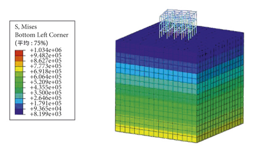
The results of the first static analysis of the model are shown in Figure 8. The ground stress balance result using the proposed method in this paper based on geometric tracing is applied to the model, and the calculation results are shown in Figure 9. For simplicity of observing the effect of ground stress balance, the upper frame is hidden.
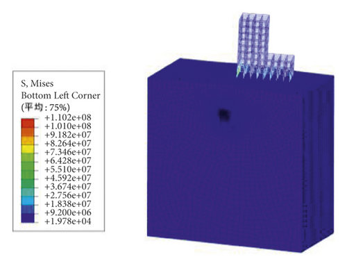
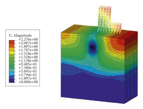
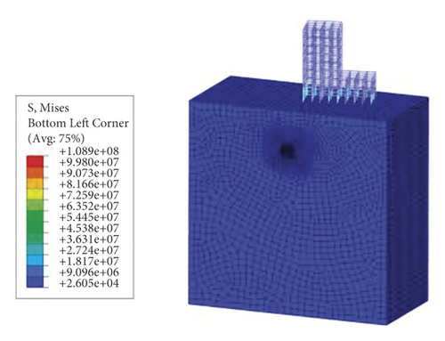
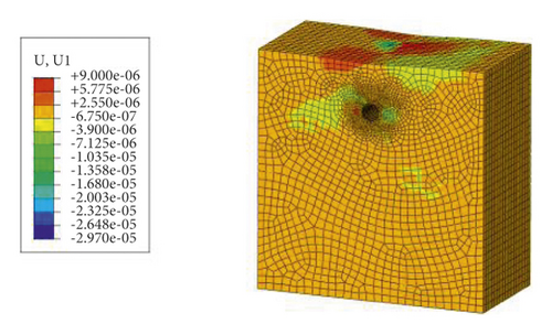
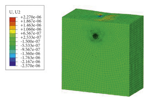
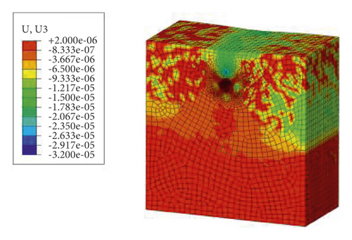
It can be seen from Figures 8 and 9 that after applying the proposed ground stress balance method to the model, the displacements of the model are kept in the order of 1 × 10⁻⁶ m, and the stress results are similar to those of static analysis, without obvious stress concentration and stress shift. It was proved that the ground stress balance method based on geometric tracing proposed in this paper is clear, converges fast, has high accuracy, and can better meet the requirements of ground stress balance for complex models.
5. Conclusion
- (1)
This paper studied the adaptiveness of the commonly used ground stress balance method, that is, the ODB import method and the automatic method, for the stratum-structure geotechnical problems. Analysis results show that the automatic method fails to coverage. For the ODB import method, as the iteration increases, the maximum displacement of the model will converge to a certain value and will no longer decrease. The converge speed and the accuracy are both low.
- (2)
Based on the analysis of the commonly used method, this paper proposed a general ground stress balance method based on the concept of geometric tracing which iteratively reconstructs the model according to the displacement field results of the static analysis and the node coordinates of the numerical model.
- (3)
A case study was carried out to test the performance of the proposed method. Test results show that the proposed method is capable of dealing with the stratum-structure geotechnical problems with complex geometry efficiently.
- (i)
The proposed method has not been applied to a constitutive model other than the elastic-plasticity model using the Mohr-Coulomb yield criterion. The adaptiveness of the method should be further investigated.
- (ii)
Structures such as existing buildings may also be affected by the method. This issue should be addressed in the future.
Conflicts of Interest
The authors declare that there are no conflicts of interest regarding the publication of this paper.
Open Research
Data Availability
The data used to support the findings of this study are available from the first author upon request.


