Practical Evaluation Method for the Pouring Scheme of a Long-Span Concrete-Filled Steel Tube Arch Bridge
Abstract
Concrete pouring steel tube arch is a critical part in the construction of a long-span concrete-filled steel tube arch bridge. With the adoption of the improved TOPSIS, this study summarized five indicators that controlled the concrete-filled steel tube pouring sequence. The indicators include the vertical displacement of the arch rib, lateral offset of the arch rib, steel tube stress, concrete stress, and elastic safety factor of the arch rib. Furthermore, a comprehensive objective function-rationalization index was proposed, based on which a practical evaluation and determination method for pouring scheme of the long-span concrete-filled steel tube arch bridge was developed. The results showed that a pouring sequence with relatively small stress in the arch rib, advanced alignment, and good stability could be determined using the proposed method.
1. Introduction
In recent 20 years, CFST arch bridge in China has developed rapidly. By 2015, more than 400 CFST arch bridges (more than 50 m) have been built in China, of which 54 have a span of more than 200 m, 11 have a span of more than 300 m, and 4 have a span of more than 400 m in China [1–5]. The completion of Hejiang No. 1 bridge marks that the concrete-filled steel tubular arch bridge has broken through the 500 m span mark. As an important construction technique for the concrete-filled steel tube arch bridge, concrete pouring in a tube is the first problem that has to be solved in order to make a remarkable improvement in the span of the concrete-filled steel tube arch bridge [6, 7]. According to the survey, many accidents were caused due to the unreasonable pouring schemes during the construction of concrete-filled steel tube arch bridges [8, 9]. In the field of determination of the optimized pouring sequence, many research works and studies were carried out. The study in [10] pointed out that different construction sequences of the arch bridge had a significant influence on the stress and stability of the structure. Therefore, the construction sequence of the arch bridge should be designed correctly in order to ensure safety during the construction process. The study in [11] considered the time-varying effect of the materials in the pouring process and suggested that the structural displacement and stress should be considered comprehensively in order to determine the pouring sequence. The study in [12] optimized the truss CFST arch bridge pouring sequence using elastic and elastic-plastic stability safety factors as indicators in order to meet the stability and safety requirements during construction. The study in [13] discussed eight representative concrete pouring sequences based on the Longbahe Super Bridge project and proposed that the evaluation of the pouring sequence should refer to the stress state of the arch foot section and the displacement state of the arch roof section. In terms of the evaluation model of the indicators, the methods proposed by scholars mainly include the comprehensive index method, analytic hierarchy process, RSR method, fuzzy comprehensive evaluation method, and gray system method [14], which is based on the life cycle assessment method [15]. Each of these methods has its characteristics, advantages, and disadvantages. Among these methods, the TOPSIS comprehensive evaluation method is used as the decision-making method in the multiobjective decision-making analysis of limited schemes in the system. Furthermore, this method is featured a simple calculation, reasonable results, and flexible application [16–21]. There are various drawbacks to employing TOPSIS [22], and at the same time, in order to avoid the interference of human subjective factors in the process of index weighting and strengthen the objectivity of evaluation, this paper selects the entropy weight method and the improved TOPSIS model for evaluation. The entropy weight method is a method to determine the index weight by the index to be evaluated. The index weight of the scheme is mainly determined by the entropy weight method according to the influence degree of the index, and it approaches the most ideal scheme to the greatest extent according to the variation degree of each index. Also, it can effectively reflect the information implied in the data and enhance the difference and resolution of the index, so as to achieve the purpose of comprehensively reflecting all kinds of information [23, 24]. With the application of the improved TOPSIS method, this study summarized five indicators that determined the concrete-filled steel tube pouring sequence, and these include the vertical displacement and lateral offset of arch rib, steel tube transient stress, concrete transient stress, and elastic safety factor. Moreover, this study proposed a comprehensive objective function of the rationalization index and analyzed the weight matrices of the five indicators against the rationalization index based on the evaluation method and index of “optimal displacement and most favorable stress” [25]. Thus, the optimized pouring sequence was determined, which was proved theoretically and validated in practice. Furthermore, the proposed method could easily determine the optimized concrete-filled steel tube arch bridge pouring scheme, thus providing evaluation and selection reference for concrete pouring sequence optimization.
2. Establishment of the Practical Evaluation Method for the Pouring Scheme
The establishment of the practical evaluation method for the pouring scheme includes the mechanism of TOPSIS and the establishment procedure. They are briefly discussed.
2.1. Mechanism of TOPSIS
After standardization, the maximum matrix is defined as z+ = (max {z11, z21, ⋯, zn1}, ⋯max {z1m, z2m, ⋯, znm}), and the minimum matrix is defined as z− = (min {z11, z21, ⋯, zn1}, ⋯min {z1m, z2m, ⋯, znm}). Then, there will be the ith object under evaluation i(i = 1,2, ⋯, n), maximum distance , and minimum distance . The nonnormalized score of the ith object is calculated i(i = 1,2, ⋯, n): . When 0 ≤ Si ≤ 1, the greater the Si value, the smaller the distance between the evaluation object and the maximum value.
2.2. Establishment of the Practical Evaluation Method for the Pouring Scheme
In equation (4), ωj ∈ [0,1] and .
3. Practical Calculation Method
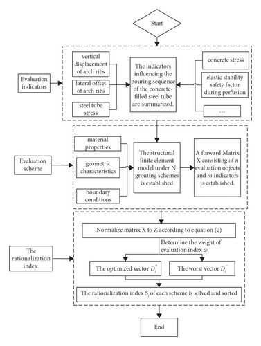
- (1)
The indicators influencing the pouring sequence of the concrete-filled steel tube, such as vertical displacement of arch ribs, lateral offset of arch ribs, steel tube stress, concrete stress, and elastic stability safety factor during perfusion are summarized.
- (2)
The number of schemes, n, is determined according to the permutation and combination rule, and the finite element model is established based on different pouring sequences and different material properties, geometric characteristics, boundary conditions, and external load of the concrete-filled steel tube arch bridge. Thereafter, each index value in each scheme is calculated.
- (3)
Then, a forward Matrix X consisting of n evaluation objects and m indicators is established.
- (4)
The weight ωj of each indicator is determined according to the variation of each indicator.
- (5)
Then, the forward Matrix X is standardized in order to eliminate the influence of different dimensions on the evaluation results, and the evaluation indexes are compared under the same dimensional system, based on the method of to obtain Matrix Z.
- (6)
Thereafter, the optimized vector and worst vector are determined, in which is the maximum normalization of the same evaluation indicator, and is the minimum normalization of the same evaluation indicator.
- (7)
Finally, the rationalization index of each scheme is solved and ranked, so that the proximity and ranking of each scheme to the ideal solution is obtained.
The flow chart for determining the optimized pouring scheme of the concrete-filled steel tube arch bridge is presented in Figure 1.
4. Application of the Practical Method
The application of the practical method includes that finite element modeling, calculation of the results, and analysis of the obtained results. They are discussed in the subsequent sections.
4.1. Introduction of the Project and the Finite Element Model
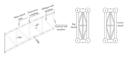
As shown in Figure 2, the main span of the concrete-filled steel tube arch bridge was taken as 575 m, and the main rib was considered to be a concrete-filled steel tube truss structure. The span was taken as 575 m, and the calculated rise-span ratio was 1/4.0. Furthermore, the arch axis coefficient was 1.50. The radial height of the vault section was taken as 8.5 m, and the radial height of the arch foot section was considered to be 17.0 m. Moreover, the rib width was taken as 4.2 m. A pair of ribs located in the upper and lower parts were installed, and these were considered to be concrete-filled steel tube strings with a diameter of 1400 mm. Thereafter, C70 concrete was considered to be poured into the tube. According to [11], there are 24 pouring sequences, which are shown in Table 1.
| Scheme | Pouring sequence | Scheme | Pouring sequence | Scheme | Pouring sequence | Scheme | Pouring sequence |
|---|---|---|---|---|---|---|---|
| 1 | 1-2-3-4 | 7 | 2-1-4-3 | 13 | 3-4-1-2 | 19 | 4-3-2-1 |
| 2 | 1-2-4-3 | 8 | 2-1-3-4 | 14 | 3-4-2-1 | 20 | 4-3-1-2 |
| 3 | 1-3-2-4 | 9 | 2-4-1-3 | 15 | 3-1-4-2 | 21 | 4-2-3-1 |
| 4 | 1-3-4-2 | 10 | 2-4-3-1 | 16 | 3-1-2-4 | 22 | 4-2-1-3 |
| 5 | 1-4-2-3 | 11 | 2-3-1-4 | 17 | 3-2-4-1 | 23 | 4-1-3-2 |
| 6 | 1-4-3-2 | 12 | 2-3-4-1 | 18 | 3-2-1-4 | 24 | 4-1-2-3 |
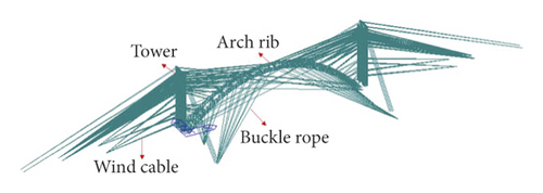
The total numbers of nodes and elements of this finite element model bridge were 12349 and 24355, respectively. The material properties, geometric characteristics, boundary conditions, and external load are the same as the data in the design drawings. The entire bridge was considered to be symmetrical. The inner tube was considered to have C70 concrete with a unit weight of 25 kN/m3 and an elastic modulus of 3.7 × 10⁴ MPa. The outer part of the arch foot section adopted C30 concrete, with a unit weight of 24 kN/m3 and an elastic modulus of 3.0 × 10⁴ MPa. The beam element was used to simulate the arch rib chord, and the double-elements method was employed to simulate the process of concrete pouring. As for the boundary conditions, the ends of the abutment and tower were fixed. Furthermore, the beam element load was applied to the corresponding position of the concrete that had not yet formed strength. After the concrete was poured, the passivation beam element load was activated by the concrete element at the same time. The finite element model is shown in Figure 3.
4.2. Calculation Process and Results
During analysis, 24 pouring sequence schemes were determined according to the permutation and combination rules. Based on different pouring sequences, as well as material properties, geometric characteristics, boundary conditions, and external load information of the concrete-filled steel tube arch bridge, a finite element model was established, and the corresponding index values of 24 schemes were calculated. The initial quantized value of the index is shown in Table 2.
| Scheme | Transient stress of steel tube (MPa) | Transient stress of concrete (MPa) | Lateraloffset(mm) | Maximumverticaldisplacement(mm) | Stabilityfactor |
|---|---|---|---|---|---|
| 1 | −145 | 3 | 0 | -458 | 12 |
| 2 | −153 | 3 | −7 | −457 | 12 |
| 3 | −146 | 3 | −6 | −467 | 12 |
| 4 | −147 | 3 | −7 | −472 | 12 |
| 5 | −153 | 4 | −4 | −468 | 12 |
| 6 | −152 | 3 | −2 | −466 | 12 |
| 7 | −148 | 3 | −2 | −472 | 11 |
| 8 | −153 | 3 | 0 | −471 | 11 |
| 9 | −180 | 3 | −12 | −569 | 11 |
| 10 | −165 | 4 | −11 | −542 | 11 |
| 11 | −154 | 3 | −11 | −454 | 11 |
| 12 | −153 | 3 | −12 | −455 | 11 |
| 13 | −147 | 3 | −9 | −471 | 11 |
| 14 | −146 | 3 | −3 | −462 | 11 |
| 15 | −155 | 3 | −7 | −457 | 11 |
| 16 | −152 | 3 | −10 | −463 | 11 |
| 17 | −153 | 3 | −6 | −465 | 11 |
| 18 | −153 | 4 | −6 | −465 | 11 |
| 19 | −157 | 3 | −65 | −473 | 11 |
| 20 | −148 | 3 | −60 | −463 | 11 |
| 21 | −155 | 3 | −66 | −466 | 11 |
| 22 | −156 | 3 | −66 | −474 | 11 |
| 23 | −152 | 3 | −59 | −456 | 11 |
| 24 | −152 | 3 | −59 | −456 | 11 |
4.3. Analysis of Calculation Results
Furthermore, the obtained results were analyzed. The rationalization index in each scheme was solved and then ranked, as shown in Figure 4.
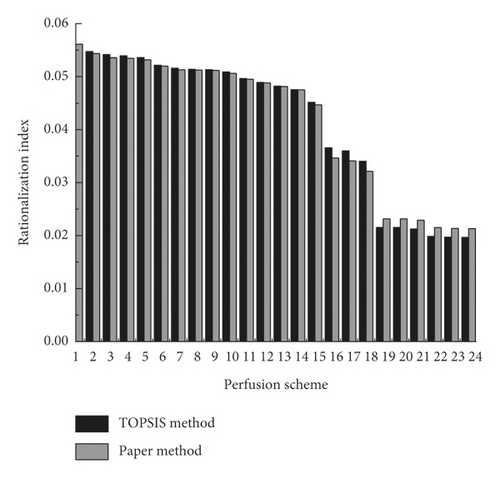
From Figure 4, it is observed that the improved TOPSIS model is more rational as it considers the weights of different indicators. Furthermore, among all the pouring schemes, Scheme 1 results in the maximized rationalization index (0.0561). In other words, when Scheme 1 was adopted, both the stress and deformation of the arch rib were small, indicating good stability of the structure. Then, it is also found that when the lower quarter was constructed initially and then followed by the construction of the inner part based on the rationalization indexes of these 24 schemes, it resulted in a relatively large rationalization index. Therefore, in practice, the method of “first lower quarter and then upper quarter, first inner part and then outer part” is the most effective pouring scheme. Concrete-filled steel tubular (CFST) method is a key procedure in the construction of the whole bridge. The perfusion schemes obtained by comparing various evaluation methods are shown in Table 3.
| Project | TOPSIS method | Paper method | Methods adopted in the literature [25] |
|---|---|---|---|
| Determination of the optimal scheme | Scheme 1 | Scheme 1 | Scheme 2 |
| Method characteristics | TOPSIS method has strong human subjectivity, which will affect the scheme results | It can effectively reflect the information implied in the data and enhance the difference and resolution of the index, so as to achieve the purpose of comprehensively reflecting all kinds of information. | The author only takes the minimum displacement and the minimum stress value as the only evaluation criteria |
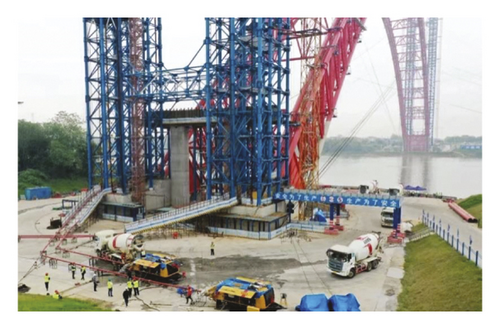
The study in [25] only takes the minimum displacement and the minimum stress value as the only evaluation criteria, and other indicators are not considered in the scheme. In addition, in order to overcome many disadvantages of the TOPSIS method, various factors should be considered. Therefore, the method in this paper is adopted, and scheme 1 is comprehensively selected for grouting. The schematic diagram of on-site concrete pouring is shown in Figure 5.
5. Conclusions
During the pouring process of long-span concrete-filled steel tubes, the distributions of load and stiffness on the structures are constantly changing. In addition to meeting the safety requirements during the construction stage, attention should be paid to the stability of these structures. Hence, various indicators had to be taken into consideration in the design and optimized pouring scheme. Based on the improved TOPSIS model, the evaluation and determination method of the concrete pouring sequence scheme that was proposed in this study was featured with a simple calculation, wide applicability, and fast selection of the arch rib structure with smaller stress and better linear shape. This pouring sequence with good stability and practical application could provide a reference for the construction control and optimization design of the same type of long-span concrete-filled steel tube arch bridges.
Conflicts of Interest
The authors declare that they have no conflicts of interest.
Authors’ Contributions
Conceptualization was carried out by H.T. and Y.X.; methodology was developed by H.T.; data curation was conducted by H.T.; writing of the original draft preparation was performed by Y.X and H.T.; reviewing and editing were conducted by D.C. All authors have read and agreed to the published version of the manuscript.
Acknowledgments
This study was partly sponsored by following fund programs: 1 National Natural Science Foundation of China (Code: 51738004).2 National Natural Science Foundation of China (Code: 51868006); 3 National Natural Science Foundation of China (Code: 51878186); 4 Guangxi Natural Science Foundation cofunded cultivation project (2018GXNSFAA138067); and 5 Nanning City “Yong Jiang Project” funded project (2018-01-04).
Open Research
Data Availability
All data included in this study are available from the corresponding author upon request.


